| Author |
 Topic Search Topic Search  Topic Options Topic Options
|
RockyBottomFarm 
Orange Level


Joined: 16 Oct 2011
Location: Fall Creek WI
Points: 253
|
 Post Options Post Options
") Thanks(0) Thanks(0)
 Quote Quote  Reply Reply
 Topic: problems with B hydraulics Topic: problems with B hydraulics
Posted: 25 Oct 2011 at 12:51pm |
reading somewhere I learned I should be able to leave pto engaged to run hydraulics, and there should be 3 positions; up, hold, and down? is this correct?
no matter which position or spot it is in it only goes up, so i just disengage the pto and it goes down, but very slow, sometimes have to get off tractor and stand on the plow.
I just changed the fluid a few hours ago, we used tractor on elevator for cob corn, ran up 23 loads of cob corn with it.
new fluid did not help, I assume something is broken....spring maybe? where can i get parts? anyone have an idea where i can get a parts breakdown or repair book?
Also need factory lever for my B hydraulics.
|
 |
|
Sponsored Links
|
|
|
JimD
Orange Level
Joined: 11 Sep 2009
Location: Mounds, OK
Points: 2116
|
Post Options
Thanks(0)
Quote Reply
Posted: 25 Oct 2011 at 12:53pm |
Nothing broken, just badly adjusted. I'll try to get something typed up when I get a break in a bit if no one else does first. If you have a manual, it's all there. JimD
|
Owner of OKtractor.com PM for an instant response on parts. Open M-F 9-6 Central. We have new and used parts. 877-378-6543
|
|
Chalmersbob
Orange Level
Joined: 11 Sep 2009
Location: Pennsylvania
Points: 2122
|
Post Options
Thanks(0)
Quote Reply
Posted: 25 Oct 2011 at 9:52pm |
what did you use for fluid?
are you sure that the lever is connected properly at the pump? It should sit in the hold position, and when pulled up it should spring back to the hold position. When pushed all of the way down, almost to the fender support angle, it should stay down, I have seen some out of adjustment linkages and some that had to be altered when they had the low seat on them. Bob
|
|
RockyBottomFarm
Orange Level
Joined: 16 Oct 2011
Location: Fall Creek WI
Points: 253
|
Post Options
Thanks(0)
Quote Reply
Posted: 26 Oct 2011 at 10:43am |
sae 30, couldnt find 20.
does not spring back at all, like i said it goes up in any position
|
|
Chalmersbob
Orange Level
Joined: 11 Sep 2009
Location: Pennsylvania
Points: 2122
|
Post Options
Thanks(0)
Quote Reply
Posted: 26 Oct 2011 at 4:37pm |
Most of us us Hydra-trans fluid. Works for both transmissions and hydraulics. 30 sae should be ok.
Look at where the rod connects to the pump valve. There are 2 disks and a spring. The rod connects to 1 disk and if it is connected with the disk in the wrong rotation it will not work right. Disconnect the rod and play with the disk. I will have to look at 1 of my B's to give you further instructions as to how if hooks up. I think the connection point is at the bottom to the front of center, this allows you to pull up and load the spring and push down with no spring pressure. Bob
|
|
RockyBottomFarm
Orange Level
Joined: 16 Oct 2011
Location: Fall Creek WI
Points: 253
|
Post Options
Thanks(0)
Quote Reply
Posted: 26 Oct 2011 at 10:50pm |
i have tried both discs in all directions and positoins, but only goes up. I do not have any linkage, and would be interested if anyone has a setup, I will take a pic in the morning of what I have.
Also pics of how it is set up on your B would be great.
thanks
|
|
RockyBottomFarm
Orange Level
Joined: 16 Oct 2011
Location: Fall Creek WI
Points: 253
|
Post Options
Thanks(0)
Quote Reply
Posted: 28 Oct 2011 at 9:15pm |
|
any help or advice?
|
|
38 & 41 B, sickle mower, 2 way plows, rear field cultivator, 2 row drill planter
40 Combine
66 Combine
Roto Baler
|
|
jccleav
Orange Level

Joined: 11 May 2011
Location: Indianola IA
Points: 211
|
Post Options
Thanks(0)
Quote Reply
Posted: 29 Oct 2011 at 9:30am |
In my book it tell how to take the pump apart and put it back together. The local agco dealer told my not to do it because mine was working. One little opps and you have to start over. It MIGHT be worth a try. To be it sounds like the valve is stuck.
Looking to the parts breakout there is a lowering rate control screw. Min is turned all the way out. It controls how much the plates can move to lower. Hope this helps some. 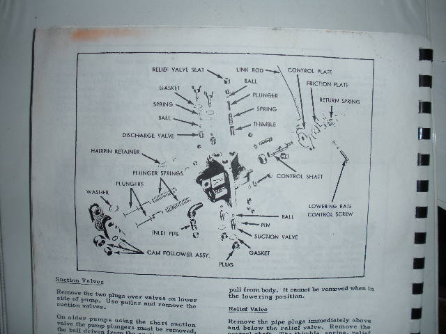
|
|
The joy is in the journey.
AC "B" and "WD" and "C"
|
|
RockyBottomFarm
Orange Level
Joined: 16 Oct 2011
Location: Fall Creek WI
Points: 253
|
Post Options
Thanks(0)
Quote Reply
Posted: 17 Dec 2011 at 4:04pm |
|
Still looking for help. Hydraulics are strong going up. Just don't go down? Looking for a lil help before I take the pump off and start tearing into it. My snow plow is all done, so now I need the hydraulics working correctly.
|
|
38 & 41 B, sickle mower, 2 way plows, rear field cultivator, 2 row drill planter
40 Combine
66 Combine
Roto Baler
|
|
Dakota Dave
Orange Level

Joined: 12 Sep 2009
Location: ND
Points: 3971
|
Post Options
Thanks(0)
Quote Reply
Posted: 17 Dec 2011 at 6:36pm |
|
JC put a breakdow drawing in the post above. you will need to take it apart clean the passageways , spring and checkballs. check the seats in the passageways for rust. and put it back together. if you back the rear tires up on ramps it will only lose a little fluid. I would drain and replace with UTF. it works much better in the cold. If you don't have the handle and control rod I don't know how your controling it. there aren't any seals inside it just springs and ball bearings. don't lose them, I take mine apart in a cake pan on the bench. after the fist one when I lost a ball.
|
|
RockyBottomFarm
Orange Level
Joined: 16 Oct 2011
Location: Fall Creek WI
Points: 253
|
Post Options
Thanks(0)
Quote Reply
Posted: 17 Dec 2011 at 7:06pm |
|
Ok. Thanks for the info. I do now have the hydraulic control lever and linkage, works good doesn't bind. It bolts on with my switching valve. Pump comes off in the morning
|
|
38 & 41 B, sickle mower, 2 way plows, rear field cultivator, 2 row drill planter
40 Combine
66 Combine
Roto Baler
|
|
RockyBottomFarm
Orange Level
Joined: 16 Oct 2011
Location: Fall Creek WI
Points: 253
|
Post Options
Thanks(0)
Quote Reply
Posted: 18 Dec 2011 at 8:29am |
dumped my fluid, pump is off, printed picture, now off to disasemble pump and look for problem. When i dumped my fluid (which now has 10-15hrs) i ran it through a paint strainter before my milk jugs and had alot of debris, remember fluid has been freshly changed and I plowed with it early fall and hydraulics went down then. I'm guessing i"ll find debris in the pump, and maybe a stuck valve or two and maybe a broken spring, wait and see. Will post pics at some point today.
jccleav------ what book or manual did u take the pic from???? TIA
|
|
38 & 41 B, sickle mower, 2 way plows, rear field cultivator, 2 row drill planter
40 Combine
66 Combine
Roto Baler
|
|
CTuckerNWIL
Orange Level

Joined: 11 Sep 2009
Location: NW Illinois
Points: 22825
|
Post Options
Thanks(0)
Quote Reply
Posted: 18 Dec 2011 at 9:05am |
|
MODELS B-C
In cases of faulty operation of the
pump valves the unit can oftentimes
be corrected without disassembly by
removing it from the tractor and
flushing it with a petroleum solvent or
gasoline.
320. R & R AND INSPECTION, Removal
of the pump from the pto housing
is accomplished by disconnecting
the hose lines and controls and removing
the bolts or screws which retain it
to the pto housing. Removal of the
pump driving camshaft which is integral
with the pto shaft is done by
following the procedure outlined in
paragraphs 311 and 312.
Procedure for bench disassembly of
the pump is as follows:
Plungers can be lifted out of their
cylinders after removing the cam arm
pins (27—Fig. AC:60 or AC161) which
are retained by hair pin locks.
Inlet valves are removed by unscrewing
the valve plugs (22) and
pulling the internally threaded seat
inserts (37) down with a sleeve and
puller screw threaded into the insert.
If seat inserts are not threaded
they can be driven out using a drift
1/32 inch smaller in diameter than the
O.D. of the insert. This method usually
calls for a renewal of the insert because
of damage done during removal.
Discharge valves (3) can be removed
by same methods used on inlet
valves after removing valve plugs (5)
I 2
27
13
23
Fig, AC160~Models B, and C power lift hydraulic pump which is of the two plunger type.
Pump is mounted on right side o# accessory units housing.
10. Relief valve ball 19. Intake valve insert
11. Relief valve spring pin
plunger 20. Intake \
1. Pump body
2. Discharge valve insert
3. Discharge valve ball
4. Discharge valve
spring
5. Discharge valve plug
6. Relief valve plug
7. Control rod
8. Outlet connection
9. Relief valve insert
12. Relief valve thimble
13. Control shaft
14. Torsion spring
15. Retaining pin
16. Shaft oil seal
17. Plunger sprinff
18. Access plug
20. intake valve sleeve
21. Intake valve ball
22. Intake valve plug
23. Intake pipe
24. Plunger
25. Cam arm
26. Cam roller
27. Cam arm pin
springs and balls. These valves are
removed through top of housing.
Control shaft (13) is removed by
first removing the washers and torsion
spring (14). Turn shaft to *lift** position
where thimble (12) is at highest
point of its travel then withdraw shaft
from pump body.
Relief valve insert (9) can be
bumped out of top of pump after removing
top and bottom plugs, ball,
spring and plunger (11).
Plungers and cylinder bores must be
free of roughness or deep scratches.
Recommended plunger to cylinder
clearance is .0002. Check cam followers
for wear or roughness and reject
any rollers which have more than .010
clearance on journal pin. Check the
valve seats and balls for grooves, pitting
or other leak producing conditions
oil leakage occurring between
control shaft and its bore in body will
show up at drilled passage between
plungers in line with control shaft
bore.
321. OVERHAUL AND TEST. If
valve seat inserts were removed by
bumping, new inserts will probably be
needed.
CONTROL SHAFT. Assemble the
control shaft to the lever so that
stop for adjusting screw in lever is
toward fiat on control shaft. Insert
shaft ihto body with flat on shaft up
and with torsion spring wound Vz turn
so as to return the control shaft to
*'hold" position.
RELIEF VALVE. With control shaft
in lowering position install in order
thimble (12), spring (32) and plunger
(11). Before installing the seat insert,
seat the ball to same by tapping
lightly with a hammer and soft drift.
Install the seat insert, drop ball into
cupped end of plunger then carefully
press seat into body until top of insert
(9) is 9/16 inch below top of hole.
DISCHARGE VALVES. Press or
bump discharge valve seat insert into
pump body until it bottoms. Discharge
valve plugs of three different lengths.
Fig. AC162, have been used in the
three different pump bodies used at
various times during the production
of the B and C tractors. When the correct
plug is used the ball end of same
will contact the spring and hold the
ball on its seat when plug is screwed
all the way down. If ball rattles when
pump is shaken or if plug cannot be
screwed all the way to its seat on
pump body the plug is incorrect for
that particular pump. The different
plugs are procurable under number
213471 short; 213005 medium; 211360
long.
INLET VALVES. Install seat inserts
up into body until top of insert pin
just clears the plunger spring (17).
|
|
|
|
RockyBottomFarm
Orange Level
Joined: 16 Oct 2011
Location: Fall Creek WI
Points: 253
|
Post Options
Thanks(0)
Quote Reply
Posted: 18 Dec 2011 at 10:14am |
|
Found a sweet answer to the problem. Sheared off pin for control shaft and plate. Gonna clean it up, put it bach together and see what happens
|
|
38 & 41 B, sickle mower, 2 way plows, rear field cultivator, 2 row drill planter
40 Combine
66 Combine
Roto Baler
|
|
RockyBottomFarm
Orange Level
Joined: 16 Oct 2011
Location: Fall Creek WI
Points: 253
|
Post Options
Thanks(0)
Quote Reply
Posted: 18 Dec 2011 at 10:32am |
|
Found a sweet answer to the problem. Sheared off pin for control shaft and plate. Gonna clean it up, put it bach together and see what happens
|
|
38 & 41 B, sickle mower, 2 way plows, rear field cultivator, 2 row drill planter
40 Combine
66 Combine
Roto Baler
|
|
Bill Long
Orange Level
Joined: 12 Sep 2009
Location: Bel Air, MD
Points: 4556
|
Post Options
Thanks(0)
Quote Reply
Posted: 18 Dec 2011 at 11:45am |
|
Looks like you have found the answer. Congratulations!!
You know, we sold the B for the sales life of the unit and I cannot recall any serious problems with the hyd. Most times it was like putting the PTO in gear or cleaning the sump. Very simple operation. Much like the tractor. Simple, Dependable.
Take good care of my favorite.
Charlie, That is an outstanding explanation. If I can I will copy it and put it in my library.
Good Luck!
Bill Long
|
|
CTuckerNWIL
Orange Level
Joined: 11 Sep 2009
Location: NW Illinois
Points: 22825
|
Post Options
Thanks(0)
Quote Reply
Posted: 18 Dec 2011 at 12:18pm |
|
Bill, I copied it right from a PDF file of the B repair manual. The only problem is it has all the numbered parts but no picture to show what parts go with what number.
|
|
|
|
RockyBottomFarm
Orange Level
Joined: 16 Oct 2011
Location: Fall Creek WI
Points: 253
|
Post Options
Thanks(0)
Quote Reply
Posted: 18 Dec 2011 at 1:00pm |
|
Also was couple other problems. The control shaft seal was not properly installed, it was only about 25% in. So I pounded it in the rest of the way. This was not allowing the control shaft to be in deep enough.
One other minor problem, the return spring is broken. Any one have one or know where to get one?
Eating lunch then going to go put pump back on
|
|
38 & 41 B, sickle mower, 2 way plows, rear field cultivator, 2 row drill planter
40 Combine
66 Combine
Roto Baler
|
|
RockyBottomFarm
Orange Level
Joined: 16 Oct 2011
Location: Fall Creek WI
Points: 253
|
Post Options
Thanks(0)
Quote Reply
Posted: 18 Dec 2011 at 7:54pm |
Well, pump is on and it works awesome!!!!!!!! took a while to get the air worked out, hose for snow plow is really long. im tired, tractor works, got cattle vaxinated this afternoon, time to go rest and then take the B to the wood tomorrow and cut firewood!!!! work on pictures tomorrow sorry guys.
|
|
38 & 41 B, sickle mower, 2 way plows, rear field cultivator, 2 row drill planter
40 Combine
66 Combine
Roto Baler
|
|
RockyBottomFarm
Orange Level
Joined: 16 Oct 2011
Location: Fall Creek WI
Points: 253
|
Post Options
Thanks(0)
Quote Reply
Posted: 19 Dec 2011 at 6:29pm |
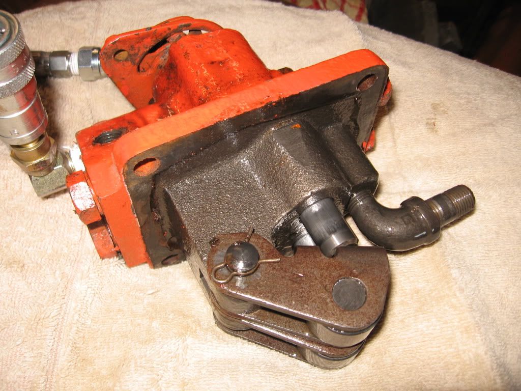
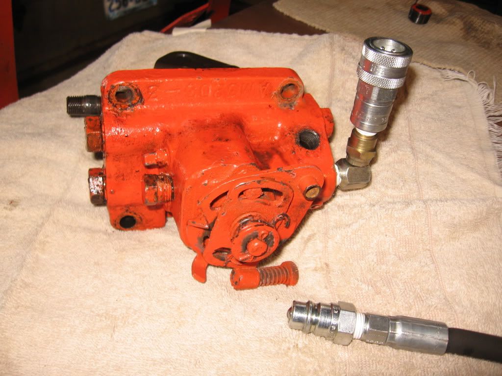
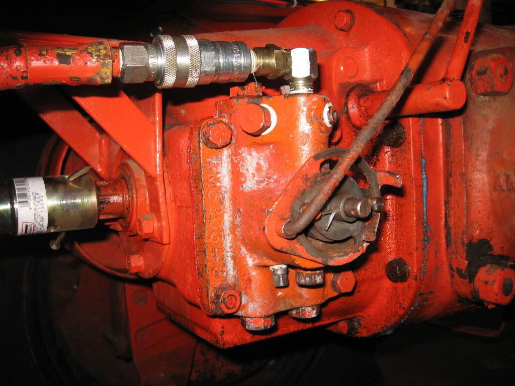
here is a couple pics of the pump off, anyone use quick couplers like me on there B or C???? very handy
Edited by RockyBottomFarm - 19 Dec 2011 at 6:34pm
|
|
38 & 41 B, sickle mower, 2 way plows, rear field cultivator, 2 row drill planter
40 Combine
66 Combine
Roto Baler
|
|
RockyBottomFarm
Orange Level
Joined: 16 Oct 2011
Location: Fall Creek WI
Points: 253
|
Post Options
Thanks(0)
Quote Reply
Posted: 19 Dec 2011 at 6:37pm |
this is the debris that came out of the trans/ rear end 
|
|
38 & 41 B, sickle mower, 2 way plows, rear field cultivator, 2 row drill planter
40 Combine
66 Combine
Roto Baler
|
|
RockyBottomFarm
Orange Level
Joined: 16 Oct 2011
Location: Fall Creek WI
Points: 253
|
Post Options
Thanks(0)
Quote Reply
Posted: 19 Dec 2011 at 6:45pm |
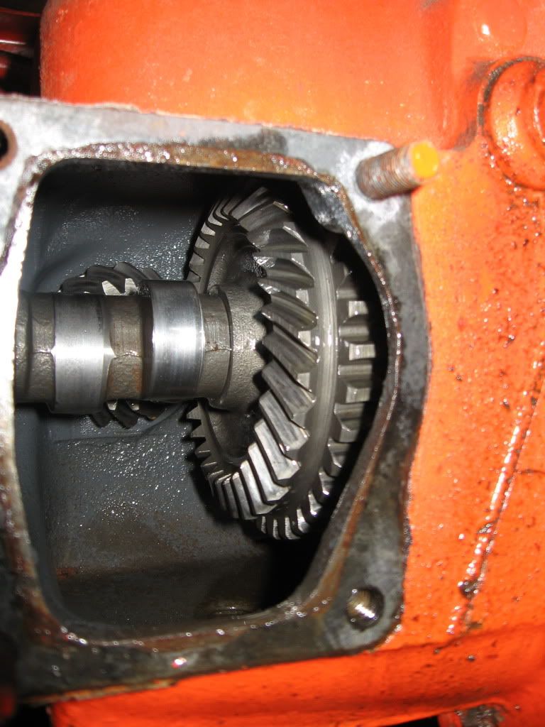
for those of you that are curious, this is the inside of the rear end, the pump runs off the two cam like lobes internally on the PTO shaft, sweet simple design.
This is my busted control spring, control plate and control shaft( you can see the sheared pin!!!)
|
|
38 & 41 B, sickle mower, 2 way plows, rear field cultivator, 2 row drill planter
40 Combine
66 Combine
Roto Baler
|
|
RockyBottomFarm
Orange Level
Joined: 16 Oct 2011
Location: Fall Creek WI
Points: 253
|
Post Options
Thanks(0)
Quote Reply
Posted: 19 Dec 2011 at 6:48pm |
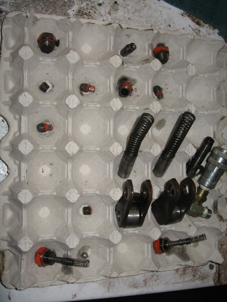
Here is my parts holder, works awesome, and the pump back on the tractor!!!!!
|
|
38 & 41 B, sickle mower, 2 way plows, rear field cultivator, 2 row drill planter
40 Combine
66 Combine
Roto Baler
|
|
BrettPhillips
Orange Level

Joined: 11 Sep 2009
Location: Strasburg, VA
Points: 808
|
Post Options
Thanks(0)
Quote Reply
Posted: 20 Dec 2011 at 2:29pm |
|
I've got quick couplers on both my B and C. Since both have 2-way valves I only have the quick coupler on the left side of the valve and the rockshaft cylinder is permanently plumbed to the right side. Like you say, it works great for snow plows and other remote uses. I have a hydraulic lift setup on my All Crop 40 header that works well too. I built it so it could be removed without a trace, so no worries about hacking it up.
|
|
stray
Orange Level

Joined: 16 Aug 2011
Location: Tipton, Missour
Points: 323
|
Post Options
Thanks(0)
Quote Reply
Posted: 20 Dec 2011 at 7:04pm |
Rockybottom, I love your parts holder I never would have thought of that.
|
|
1969 190XT series 3
|
|