| Author |
 Topic Search Topic Search  Topic Options Topic Options
|
Nathan (SD) 
Orange Level

Joined: 11 Sep 2009
Location: Day County SD
Points: 1243
|
 Post Options Post Options
") Thanks(0) Thanks(0)
") Quote Quote  Reply Reply
 Posted: 30 Apr 2011 at 12:40pm Posted: 30 Apr 2011 at 12:40pm |
Instead of wasting that good 4 hole pulley. Use your original pulley and just weld your splined stub into the pulley center. You have all the tools to keep it centered and true.
I did it that way to a WD about 15 years ago and it is still going. I had crude tools. I used a 5/8 keyed shaft pump slipped right in the hub and tightened the setscrew. I had a little wobble noticeable at the end of the pump. I made a mounting by the pump flange on one side to hold the pump from spinning. The wobble was not noticeable there so I just sanwiched a rubber washer between the flange and my mounting.
If your are gonna have two splined connections, meaning no set screw anywhere, I think you should have some courser splines in the pulley hub.
I read all your info but didn't see any reference to either end having a setscrew.
|
 |
|
Sponsored Links
|
|
|
DaveKamp
Orange Level Access
Joined: 12 Apr 2010
Location: LeClaire, Ia
Points: 5645
|
Post Options
Thanks(0)
Quote Reply
Posted: 30 Apr 2011 at 9:38am |
So here, I've used the coupler-shortener/shaft-straightener (also square and oblong roundener, and if I so desire, cam-lobe-maker: 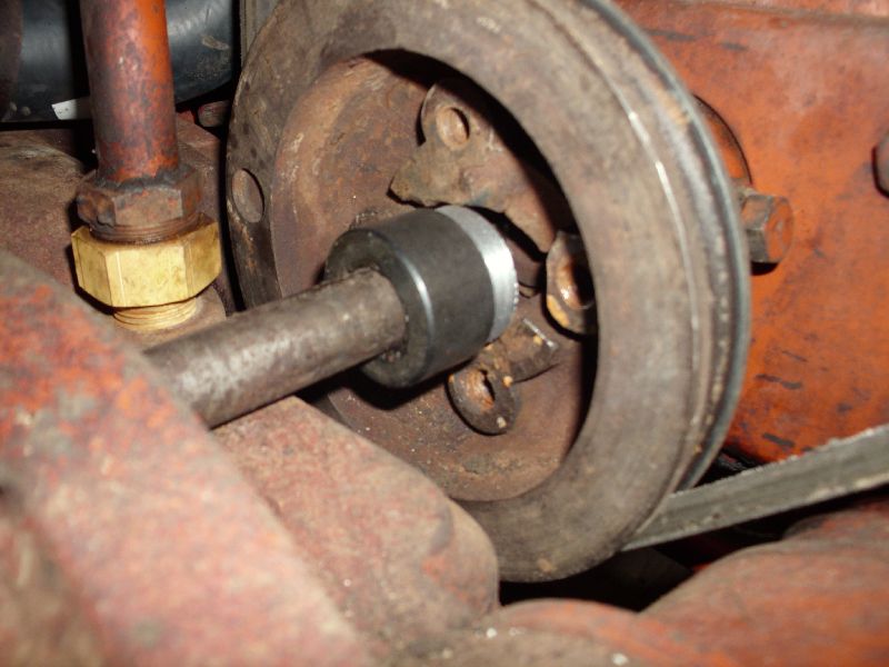 First, I sawed it off with a bandsaw, then I put it in the lathe, and cut it down to appropriate length (trued up the end, 'cause bandsaws ain't known for precision)... then I cut a shoulder in it. I'll cut a plate that fits the hole pattern and fit the coupler in there. Now, for those of you that are machinists, the rest is elementary, but most folks don't have a lathe in their workshop (much less five), so bear with me while I put a little explanation here... The mother of ALL machine tools is the lathe. A lathe holds and rotates a workpiece, while a cutter is put against it. 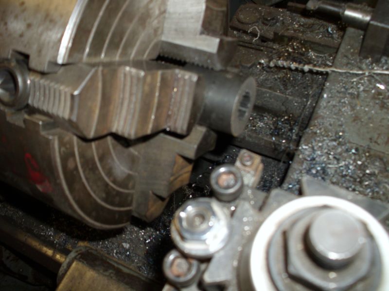 The basic concept is making something round out of something that isn't, but what's REALLY happening, is that you're establishing an AXIS, and then making CONCENTRIC CUTS around it. This is important to remember, and when I make the rest of the coupler, I'll explain not only how I do it, but WHY I do it that way. With ANYTHING, there's always more than one way to get something done... when making precision parts, there's advantages and benefits to every method... but also costs and challenges. Operating machine tools is only a small part operating, and the rest is about thinking ahead so that you do things in an order that make your workpiece more accurate at each step, rather than compound an inaccuracy at each step. In the case of this collar, I put it in the lathe chuck, and used a dial indicator against the OUTSIDE of the collar to get it roughly centered... then I took a piece of shaft material, polished it, and slid it into the splined center, and put the indicator against IT... and adjusted the chuck again. This is because the collar's hole and splines MAY NOT have been concentric to the OUTSIDE in manufacture. These collars are clearly US-made, by a reputable manufacturer, because it was within 0.0004" of concentric. I also checked the amount of 'wobble' at the far end of the shaft, and found that 18" out, it was still under 0.0007", so really danged true. Many (like the imported sheaves and collars found at farm stores and import-tool outlets) are off by lots... 0.004" or more... and they're frequently way out'a square (they'll wobble like crazy 18" out) so if you trust the OD, you're screwed- it never runs true. More on this later! Here's a quick look at how the pump fits the front of the bolster. In finished form, I probably won't have it recessed that deep, but we'll see what I can do to get it close. I don't like big things hangin' out the front, to get tangled up in stuff. 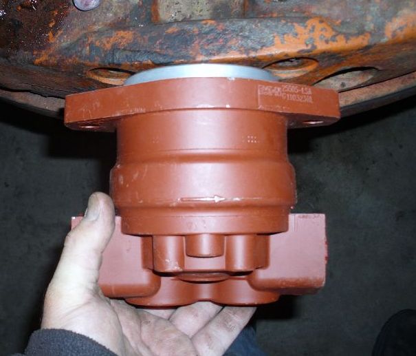 Notice the direction arrow on the pump? Handy!!! Yes, the crankshaft, when viewed from this end, is spinning clockwise. The pump, since it's FACING the engine, must be the CLOCKWISE type. SOME pumps are reversible... if you're willing to disassemble them and re-orient some components, but many aren't. IF you look in a dismantled pump, you'll see that there's little passages at each end... they go from one side cavity (the high pressure side) to the bearing shell. Then there's oftentimes a passage that goes from the far end of the bearing, to the LOW pressure side. When operating, the pump's output pressure forces oil into the bearing space, to hydraulically 'float' the shaft between bearing and shaft, just like the crank mains and rods of an engine. There's also high-pressure oil forced along the edges of the pump's gears to minimize surface contact force against the sealing face 'wear plates', cooling the gears and minimizing wear. This is one of the first reasons why it is so important to keep hydraulic fluid clean, and level proper to prevent aereation (bubbles). This pump ain't exactly cheap, but it should last my lifetime's worth of abuse with minimal care. There's cheaper pumps out there, and different shapes. I selected it for it's shorter length, side-ports, and robustness. One could use a longer pump, with end-mounted plumbing, but it'd require additional plumbing fittings to reach, and would be very susceptable to pump and plumbing damage.
Edited by DaveKamp - 30 Apr 2011 at 9:47am
|
|
DaveKamp
Orange Level Access
Joined: 12 Apr 2010
Location: LeClaire, Ia
Points: 5645
|
Post Options
Thanks(0)
Quote Reply
Posted: 30 Apr 2011 at 8:38am |
Okay, got a little done yesterday afternoon and last night: Got the coupler... this fits a 7/8" x 13 spline shaft. It's a little bit long, but I've got a shortener in here somewhere... 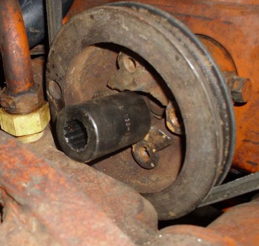 Next: Here's the pump. It's an EATON / Cessna, about 2.6gpm... I posted this, and the coupler part number and source in previous post. 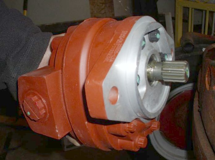 The form-factor of this pump... actually the standard mounting face, is an SAE B 2-bolt mount. The distance between bolt and pilot centers is standardized, as well as hole sizes. There's several different shaft styles that are common to the SAE B, I selected 7/8-13 spline for two reasons- FIRST... it's a common size also used in SAE A pumps (which, for someone wanting less volume, you can simply substitute a smaller pump, and use the SAE A bracket sizing)... and Second, because I"m making this setup so that I can easily pull the pump off, either for service, or to pull the shaft out, thus, removing the engine load when I'm not in need of live hydraulic power. FINALLY, I'm not using a 'soft' coupling or flexible, because I'll be making the mounting arrangement so that the pump is free to 'float', thus, it will WANT to maintain alignment with the crankshaft centerline. There's enough play in the splines (not lots, but enough) so that they'll slip together, and the weight of the pump and plumbing is well within the pump bearings' support capacity, the only thing the bracket will have to do is 1) keep the pump from falling off, and 2) keep it from spinning. Many live hydraulic kits rigidly mount the pump to the frame, and then use flexible couplings at both ends of the shaft. This means the coupling becomes compliant, subject to wear and stress over time, hence, contributory to failure. One of the worst things I can think of here, is having the coupler bolts break off, and having three more in there that I can't back out without taking the bolster off, or worse yet, pulling the engine. Next, I'd hate to hafta try to dismantle it with the pump and plumbing in the way... it'd almost certainly involve applying a cutting torch or sawzall to the shaft to get it out. An IDEAL mounting situation, would be nothing more than sliding the pump onto a coupler right at the crankshaft pulley... and then putting a torque-arm on the pump that keeps the pump from sliding out. Bolster is in the way here, so I gotta 'stretch' it out a bit, which means I'll hafta keep the splined shaft straight, so the pump doesn't 'wobble', but if it does, the mount will allow it... it'll just vibrate alot. Luckily, my coupler-shortner is also a shaft-straightener...
Edited by DaveKamp - 30 Apr 2011 at 8:57am
|
|
DaveKamp
Orange Level Access
Joined: 12 Apr 2010
Location: LeClaire, Ia
Points: 5645
|
Post Options
Thanks(0)
Quote Reply
Posted: 29 Apr 2011 at 9:04am |
|
Well, I'm glad I had everything shipped ground, 'cause UPS's hub got a little plugged-up with the storms. Tracking reports that by end-of-biz today, I'll have the splined couplers, a pump, and upper/lower radiator hoses... I'll put in a little wrench time between now and Sunday so I can get the 17 up and operable... need to drag some stuff off the trailer for a run down to Tennessee on Tuesday... it'll stall my progress for a little bit, but it'll give me time to measure and calculate and order the shaft. Won't take me long to finish up the kit when I return!
|
|
JayIN
Orange Level

Joined: 18 Dec 2009
Location: SE/IN
Points: 1982
|
Post Options
Thanks(0)
Quote Reply
Posted: 28 Apr 2011 at 7:13am |
|
Yeah, keep us informed! I was lucky, my D15 already had a front pump on it.
|
|
sometimes I walk out to my shop and look around and think "Who's the idiot that owns this place?"
|
|
Brian Jasper co. Ia
Orange Level
Joined: 11 Sep 2009
Location: Prairie City Ia
Points: 10508
|
Post Options
Thanks(0)
Quote Reply
Posted: 27 Apr 2011 at 10:03pm |
 DaveKamp wrote: DaveKamp wrote:
Hee hee... thanks for the tip... but believe it or not, with all the crud I blasted off, that darned socket was somehow devoid of the grime-monster... there was a little I picked out, but most was from me movin' the bolster around.
My preferred mode of operation, is to hose everything down good with a pressure-washer before I start. I miss lots of places, so I end up with 'temporary tattoos', but biggest concern is to make it so I can find the darned fasteners, and don't lose grip of my wrenches... keeps me from getting unnecessary dents in my head... keeps the shop cleaner, but no matter how hard I try, there's always something in there somewhere.
|
I see I'm not the only one with that issue. LOL
|
|
"Any man who thinks he can be happy and prosperous by letting the government take care of him better take a closer look at the American Indian." Henry Ford
|
|
sks72107
Silver Level

Joined: 30 Sep 2010
Location: Logansport, IN
Points: 441
|
Post Options
Thanks(0)
Quote Reply
Posted: 27 Apr 2011 at 11:36am |
Id really like to see some pics of this after completion. I may do it to my series 1 someday, mine already has the 4 hole pulley. great work!!!
|
|
BobHnwO
Orange Level

Joined: 16 Sep 2009
Location: Jenera Ohio
Points: 693
|
Post Options
Thanks(0)
Quote Reply
Posted: 27 Apr 2011 at 11:36am |
|
Dave,Thanks for the info so far and keep riden that horse,lol.
|
|
Why do today what you can put off til tomorrow.
|
|
DaveKamp
Orange Level Access
Joined: 12 Apr 2010
Location: LeClaire, Ia
Points: 5645
|
Post Options
Thanks(0)
Quote Reply
Posted: 27 Apr 2011 at 11:28am |
|
Hee hee... thanks for the tip... but believe it or not, with all the crud I blasted off, that darned socket was somehow devoid of the grime-monster... there was a little I picked out, but most was from me movin' the bolster around.
My preferred mode of operation, is to hose everything down good with a pressure-washer before I start. I miss lots of places, so I end up with 'temporary tattoos', but biggest concern is to make it so I can find the darned fasteners, and don't lose grip of my wrenches... keeps me from getting unnecessary dents in my head... keeps the shop cleaner, but no matter how hard I try, there's always something in there somewhere.
|
|
Brian Jasper co. Ia
Orange Level
Joined: 11 Sep 2009
Location: Prairie City Ia
Points: 10508
|
Post Options
Thanks(0)
Quote Reply
Posted: 27 Apr 2011 at 8:00am |
|
Dave, sounds like you have the bolster back on. I was going to say clean any junk out of that splined hole. The input shaft on your power steering valve slides in and out a small amount to function. And for those wondering, the pins for the u joint are tapered. A combination of an air hammer and one of the side frame rails to back up the shaft got the job done. A hand sledge and large punch pretty much just bounced.
|
|
"Any man who thinks he can be happy and prosperous by letting the government take care of him better take a closer look at the American Indian." Henry Ford
|
|
DaveKamp
Orange Level Access
Joined: 12 Apr 2010
Location: LeClaire, Ia
Points: 5645
|
Post Options
Thanks(0)
Quote Reply
Posted: 27 Apr 2011 at 7:53am |
Here's what I found, but if you're gonna copy my work, don't do it yet- let me 'fall off the horse' first! 9-4068-C 2.61 cu in CESSNA 25505LSA HYD PUMP 354.95
1-1392 7/8" 13T SPLINED COUPLING 163-1413 17.00
I'll probably cut one coupler in half, and fit it to a disk to fix to the engine end, and use the other coupler half on a piece of shaft that's been splined at the engine-end. The Cessna pump is a very 'short' package, with ports located on the sides. 2.6ci will give me around 6 and a half gallons/minute at idle. Here's how I figured that out: 1 gallon - 231 cubic inches (remember, the Buick 231 V6 was a 'one gallon wonder') To make one gallon, the 2.6ci pump needs to rotate 231 / 2.6 = 89 rotations... at 89rpm, that's one gallon. Let's say I'm idling at 600rpm... that means I'll be churning through 600/89 = 6.7 gallons. At 1800, I'll be getting 1800/89 = 20. Now, as another noted above, 20gpm is quite a bit. Most guys won't need that much flow... matter of fact, unless you know that you'll be running a hydraulically motor driven load (like a brush, or saw, or auger, or concrete breaker), I'd say size the pump around half that. I chose this size knowing FULL WELL, that I'd probably run that pump only SOMETIMES, and swap to a smaller pump OTHER times. I'll build my whole system assuming 20gpm... hoses, valves... all of it... and if I don't need the capacity, I'll have an identical, but smaller pump... with ADAPTER FITTINGS, so that I can swap in say... a 1ci pump... which will put me at 1 gallon @ 231rpm... or about 3 gallons/minute at 600rpm. Much more reasonable for most uses... throttle it up to 1200, and you'll run a full hydraulic loader nicely. In my case, I'll be running a backhoe that works casually around 4-5gpm, and hard around 8... but a concrete breaker that requires 15 BY ITSELF. Granted, the breaker isn't exactly operating concurrently to swinging the boom, but I do push, lift, hook, and pry while the breaker is running, so NOT having the volume is very frustrating. I operate skid-steers with similar breakers, and they're all running 20gpm or so on the motor circuit, and I over-run them, so I'm certain that if I only fitted my setup for 6-8gpm, I'd be frustrated by slow progress and low power. My other option, would be to have a 'split pump', one high, and one low-volume... but it's added complexity, added drag, and they stick out farther from the front. I want this to be a tidy little setup that doesn't attract roosting chickens, doesn't get banged against things, and LOOKS like it was intended that way... but also... very, very, very easy to work on, and with.
|
|
BobHnwO
Orange Level
Joined: 16 Sep 2009
Location: Jenera Ohio
Points: 693
|
Post Options
Thanks(0)
Quote Reply
Posted: 27 Apr 2011 at 4:48am |
|
Dave,what is the number of the pump you got from Surplus Center,Thanks.
|
|
Why do today what you can put off til tomorrow.
|
|
Steve M C/IL
Orange Level
Joined: 01 Jul 2010
Location: shelbyville IL
Points: 691
|
Post Options
Thanks(0)
Quote Reply
Posted: 26 Apr 2011 at 11:56pm |
|
Ordered from S/center 2 weeks ago today(Tues)....they said we're really busy,it'll 4-5 days before we can ship it.Got it the next week on Thursday.Oh well.
|
|
DaveKamp
Orange Level Access
Joined: 12 Apr 2010
Location: LeClaire, Ia
Points: 5645
|
Post Options
Thanks(0)
Quote Reply
Posted: 26 Apr 2011 at 9:59pm |
|
No workshop progress to report, but last Thursday I placed two orders... one from Surplus Center (in Lincoln, Nebraska) for some splined shaft collars and a pump... the other from Steiner Tractor to get an upper and lower radiator hose... was hoping to have 'em show up here around Wednesday/Thursday or so, so I'd be able some wrench and machine-shop time in (fab the coupler, measure the shaft, put the radiator back on, get the tin on, running and operational while I do the 'rest' of the engineering and fab work...
Wouldn't 'ya know it... BOTH orders have been sitting... (sigh). Dunno how it works elsewhere, but when an order is placed at my company, it gets processed, pulled, and if it's ready before 4pm, ships the same day... regardless of how flooded we get with shipments... (shrug)
So I did something else instead. It DID ease up on the rain for a little bit, but would'a been a good evening to turn wrenches and make metal chips.
|
|
E7018
Bronze Level

Joined: 07 Dec 2009
Points: 167
|
Post Options
Thanks(0)
Quote Reply
Posted: 24 Apr 2011 at 10:22pm |
|
If Des Moines seems easier, leave it with the receptionist at this place, say "for Clint".
http://www.bbsae.com/
|
|
DaveKamp
Orange Level Access
Joined: 12 Apr 2010
Location: LeClaire, Ia
Points: 5645
|
Post Options
Thanks(0)
Quote Reply
Posted: 24 Apr 2011 at 10:17pm |
|
Could- my in-laws live just off the Van Meter exit... Marshall works weekends near the west end of 235...
|
|
E7018
Bronze Level
Joined: 07 Dec 2009
Points: 167
|
Post Options
Thanks(0)
Quote Reply
Posted: 24 Apr 2011 at 9:22pm |
|
Downtown Des Moines any easier?
|
|
allis restorer
Silver Level

Joined: 05 Dec 2010
Location: Rib Lake, WI
Points: 184
|
Post Options
Thanks(0)
Quote Reply
Posted: 24 Apr 2011 at 9:11pm |
Dave heres a pic of mine i just got done a little while ago putting a pump on my D17 Series 1. 
|
|
Go orange or Go home!!
|
|
DaveKamp
Orange Level Access
Joined: 12 Apr 2010
Location: LeClaire, Ia
Points: 5645
|
Post Options
Thanks(0)
Quote Reply
Posted: 24 Apr 2011 at 8:56pm |
|
Dennis - the 2-bolt sheave has been transported to my in-law's, house, Marshall will sneak over sometime in the next few days, pick it up from the in-laws, and drop it over where he picked it up... unless you want it somewhere else.
|
|
DaveKamp
Orange Level Access
Joined: 12 Apr 2010
Location: LeClaire, Ia
Points: 5645
|
Post Options
Thanks(0)
Quote Reply
Posted: 24 Apr 2011 at 10:27am |
|
Lloyd- the fluid power and mechanical engineering, I have plenty of knowledge in... and as much as I've operated a D-17, doing anything other than checking oil was off-limits on Grandpa's fleet... even HE didn't work on his own stuff. (strange, but true)... so there's some workin'-on-it wisdom out there that others have, that I don't have yet... the kinds of things that don't show up in the service manuals, but should...
|
|
DaveKamp
Orange Level Access
Joined: 12 Apr 2010
Location: LeClaire, Ia
Points: 5645
|
Post Options
Thanks(0)
Quote Reply
Posted: 24 Apr 2011 at 10:25am |
|
Dag, Bri- well, 'ya can't see it in the picture, but the early pulley has TWO threaded bolt holes in it. I've got the center dimensions measured, so I can rattle 'em off to 'ya later. I had a pair of bolts that didn't match the threads, but they were slightly smaller and would slip through just fine, and I was able to fish 'em in and thread nuts on the back. The plate is just a flat metal square... I used a dial caliper to find the center distance, drilled the plate, dropped it in there... and just before tightening 'em down, threaded on a piece from my slide hammer to pull against the plate.
|
|
Brian G. NY
Orange Level

Joined: 12 Sep 2009
Location: 12194
Points: 2201
|
Post Options
Thanks(0)
Quote Reply
Posted: 24 Apr 2011 at 10:00am |
Dave, Run by me again how you bolted the puller plate to the old pulley (sheave);
were there holes in it already or did you drill and tap holes?
Any holes in the old pulley are not obvious in your pics.
Maybe I missed something?
|
|
Loyd
Bronze Level
Joined: 16 Apr 2011
Points: 16
|
Post Options
Thanks(0)
Quote Reply
Posted: 24 Apr 2011 at 8:55am |
|
Dave,
It is looking good! I wish I had 1/2 of the knowledge you have on this stuff. Keep up with the details....I am soaking it up!
Thanks,
Loyd
|
|
DaveKamp
Orange Level Access
Joined: 12 Apr 2010
Location: LeClaire, Ia
Points: 5645
|
Post Options
Thanks(0)
Quote Reply
Posted: 24 Apr 2011 at 12:23am |
|
Lloyd- I won't have a sketch yet, but I'll probably have one by virtue of making the pieces, and I'll share 'em with anyone who'd like 'em.
The CASE/Harvester pump drive coupler is a nice piece- a die-forging, probably. I don't have facilities to do any castings here yet... and will likely never be able to do any die-forging, but I've got about twenty-five machine tools, three torches, and seven welders in my shop, about the only thing I REALLY wished I had, is a CNC cutting table... something I could put a plasma OR gas torch on. I've got about 50% of the parts to build one, but the time, and available shop space aren't there yet... it'll hafta wait 'till the big workshop is done.
In the meantime, all the parts I'll use will either be very generic off-the-shelf, or easily fabricated from generic off-the-shelf stuff, so anybody with a lathe and drill press should be able to copy it pretty easily.
|
|
DaveKamp
Orange Level Access
Joined: 12 Apr 2010
Location: LeClaire, Ia
Points: 5645
|
Post Options
Thanks(0)
Quote Reply
Posted: 24 Apr 2011 at 12:16am |
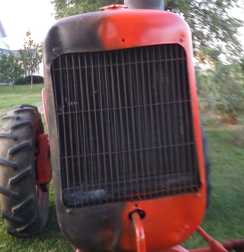
And here's the 'new' 4-bolt sheave in place, with bolster ready to slide back into position... 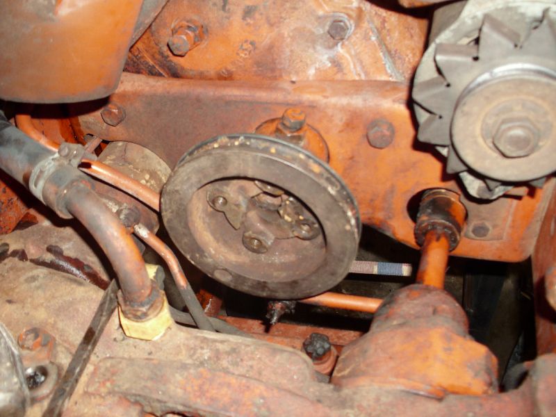 I got it all back in and hooked up, belt back on, etc. I could put the radiator and front shell back in tomorrow, but I'm gonna let it wait 'till Monday evening- gonna pull the thermostat and test it (she doesn't warm up much), flush out the rad, and put it all back together with new hoses. Got family obligations tomorrow, but if there's a break, I'll pull the hand-start B out and reinstall a broken off drawbar... and in the meantime, I'll start fabricating the splined-shaft coupler and front bracketry.
|
|
DaveKamp
Orange Level Access
Joined: 12 Apr 2010
Location: LeClaire, Ia
Points: 5645
|
Post Options
Thanks(0)
Quote Reply
Posted: 24 Apr 2011 at 12:11am |
Here's the splined shaft, viewed from below: 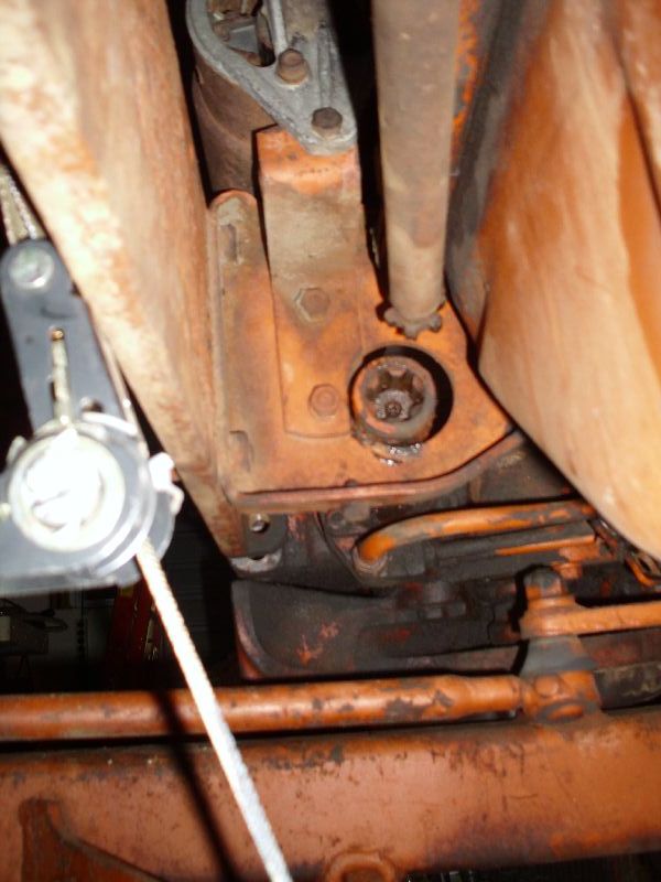 And here's the part I thought would be the most annoying, but turned out to be simple... two bolts holding the axle yoke to the bellhousing... had'ta blast more grime off to see it clearly, and clearly needed some more grime-blasting. 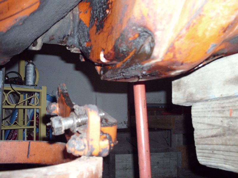 Here's the metal plate I used for pulling the old sheave out:  It was made from junk that was just-lying-around. Actually, it was a shim plate from a scale... I frequently end up with extras...
|
|
DaveKamp
Orange Level Access
Joined: 12 Apr 2010
Location: LeClaire, Ia
Points: 5645
|
Post Options
Thanks(0)
Quote Reply
Posted: 24 Apr 2011 at 12:05am |
Thanks for the helpful hints, guys- yep, the splined steering shaft slid right out, no problem, so one less headache there. I was somewhat foiled by the lower hydraulic line going to the bolster right down by the steering shaft... stuck, and I didn't have a big enough line-wrench, but I noticed that it was clear to move forward if I detached the line at the pump end, and removed one 3/4" headed bolt under the engine mount. The little screw holding the retainer strap was so crammed, in, I couldn't get a wrench on it, so yanking the big bolt was easy and fast. Unhooked the suction line at the pump end, and shoved rubber stoppers in both lines, so it didn't spill much oil. Had a cookie sheet on the floor to catch the dribble, and the frame rail is well lubricated, but all's well. 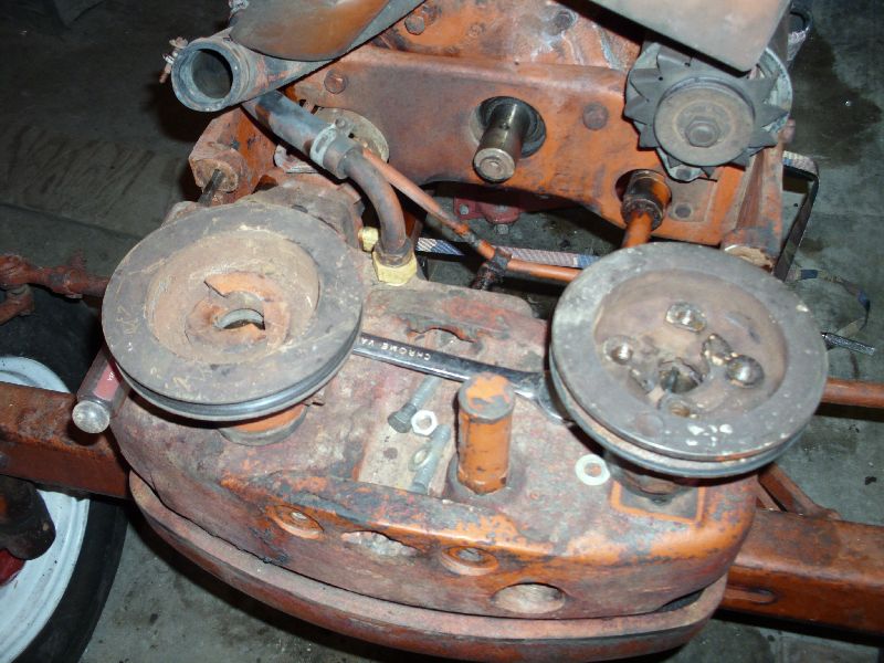 To remove the sheave, I pulled the taper-headed locking bolt totally out as suggested (I'd dealt with these before on my '48 B). I only slid the frontend forward about eight inches, and was able to thread a piece of 1/4" plate with three holes in there, used two bolts through the sheave's bolt-holes, and ran a long fine-threaded rod (actually, the handle to my slide-hammer) in there, just spun the handle to push the pulley off the crank. It wasn't FAST to come off, but it didn't take a scary amount of effort to get it popped loose. 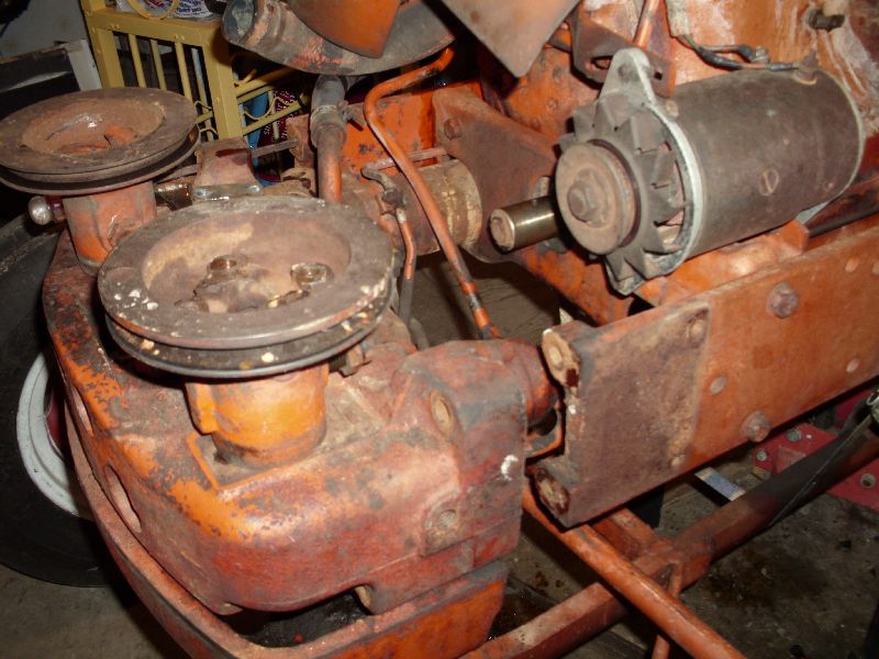 There's about all the farther I had to go to get the old one snuck out, and the new one installed. There WAS a key in the keyway... and it didn't give me a lick'a trouble. To get the new one in, I just started it by hand, wiggled it down 'till it really wanted a rappin', then I put a block of wood on it, stuck a steel rod through the crank guides, and tapped on it with a 4lb machinist's hammer. I was careful to watch the tapered-bolt hole carefully, and stop when I got the crankshaft hole to line up with the bolt. 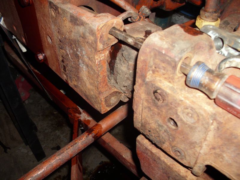 One thing I found somewhat odd, is that the bolster doesn't like to roll straight out of the frame. The steering coupler likes to get hung up on the hole, and the steering ram doesn't clear the frame-rail bosses unless you pull it out cock-eyed. It was somewhat of an exercise of frustration, because I'm limited to 15lbs lifting right now, but doc says I can push, drag, or shove anything I want with my lower body, so I used a couple of ratchet straps, some various metal scraps, etc., to get it slid out, then pushed back in and lined up.
|
|
Steve M C/IL
Orange Level
Joined: 01 Jul 2010
Location: shelbyville IL
Points: 691
|
Post Options
Thanks(0)
Quote Reply
Posted: 23 Apr 2011 at 11:53pm |
|
Dad worked on scads of WD's and 45's and a few 17's.Only pulley set up I've seen had tapered set screws.Thats how my 45 is.Not saying yours don't but I've never seen one with a keyway.
|
|
MACK
Orange Level
Joined: 17 Nov 2009
Points: 7664
|
Post Options
Thanks(0)
Quote Reply
Posted: 23 Apr 2011 at 9:31pm |
|
Pirlbeck is right. Get the generator out of your way and with a big hammer and a large long punch beat it off. Forget about a puller, it will only cost you when you break your pulley. MACK
|
|
Loyd
Bronze Level
Joined: 16 Apr 2011
Points: 16
|
Post Options
Thanks(0)
Quote Reply
Posted: 23 Apr 2011 at 7:53pm |
|
Dave,
Do you have a sketch of your final idea? I have a series 1 and would like to do something like you are doing. I also may come up with some ideas. I have been a machinist for over 30 years. I have done machining on F-16, F-18, L-1011, Maverick Missiles and Blackhawk helicopters. Not counting sawmill, concrete and all kinds of other machinery over the years.
I may not know much about tractors but I might be able to come up with an idea or two. I also have a cnc plasma machine that is useful for making special brackets etc.. I just reworked a bushhog today for a fellow. I am learning a lot about AC's by reading the posts! Keep up the good work!
Loyd
|
|


