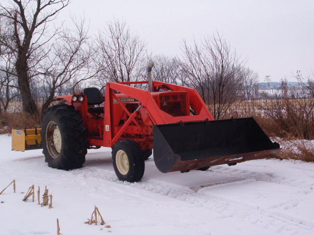
D17 Live Hydraulics project
Printed From: Unofficial Allis
Category: Allis Chalmers
Forum Name: Farm Equipment
Forum Description: everything about Allis-Chalmers farm equipment
URL: https://www.allischalmers.com/forum/forum_posts.asp?TID=29427
Printed Date: 30 Mar 2026 at 10:10am
Software Version: Web Wiz Forums 11.10 - http://www.webwizforums.com
Topic: D17 Live Hydraulics project
Posted By: DaveKamp
Subject: D17 Live Hydraulics project
Date Posted: 20 Apr 2011 at 1:32am
|
Hi All! I'm starting the live-hydraulics installation project for my D17 Series 1. I've got an aftermarket kit which contains, amongst other things, a shaft and coupler. The coupler is a flat disk with four holes, and a keyed hub welded on, and a 3/4" keyed shaft long enough to reach from said coupler to the front of the bolster casting. When I initially looked at the crankshaft sheave, I saw threaded bosses to connect to a puller or pump coupler, but what I didn't realize, is that there was only two threaded holes, not four... and there's an overrunning rampset for using a hand-crank. SO... obviously there's a different front sheave available that has four bosses, and perhaps has a flat surface (rather than overrunning ramps) onto which a front pump shaft coupler can mount. Is there a common technique for coupling to my existing sheave, or would I be best to seek a NOS supply of the latter 4-bolt sheave? If so, who would have a good example... and finally... It appears that removing said sheave requires removing the whole front end bolster... unhooking steering shaft, jacking up the engine/frame side, and supporting the axle, unbolting and sliding it forward... can this be done with the power-steering lines connected (just move it a little), or will I have to pull it far out to get the current sheave off the crankshaft? Are there any BETTER ways of making this all happen? Anybody got pictures? |
Replies:
Posted By: Brian Jasper co. Ia
Date Posted: 20 Apr 2011 at 6:50am
|
I'm going to say no. You'll need a gear puller to remove the frony pulley. No question about that on the diesel. Your bolster will have to come down. ------------- "Any man who thinks he can be happy and prosperous by letting the government take care of him better take a closer look at the American Indian." Henry Ford |
Posted By: B26240
Date Posted: 20 Apr 2011 at 7:03am
| I put one on a WC years ago and I used lathe , machined of the ramps, cut a very small grove at the right radius of holes then drilled and taped bolt holes. |
Posted By: farmtoybuilder
Date Posted: 20 Apr 2011 at 7:40am
|
You can use 2 holes to attach plate to pulley. The other two attach the shaft hub to disc. Like the AC-Simpicity garden tractor drive shafts are! And other old loader tractors use 4 bolt hubs-disc and used two in pulley's and other 2 for drive shaft. I don't have a picture of them. They use Heavy flat washers next to disc and spacers if needed and last a long time. ------------- 5 different TT-10's,5 TT-18's Terra Tigers,B-10,2 B-207's,B-110,2 B-112's,HB-112,B-210,B-212,HB212,2 Scamp's & Homilite T-10. Still hunting NICE HB-112 & anything Terra Tiger & Trailers for them. |
Posted By: E7018
Date Posted: 20 Apr 2011 at 8:04am
|
Dave, I could probably pull the pulley off the engine that ran that that setup. A guy was going to buy the engine but hasn't showed up. ( The second guy that said that.) The front casting will have to come away to have room to change the pulley. ( 4 frame bolts and power steering lines, radiator, of course.) If you take that away, maybe it isn't any harder to make a different coupling to hook to the present pulley. You see what looks easiest. |
Posted By: DaveKamp
Date Posted: 20 Apr 2011 at 9:48am
|
Hmmm... Thanks 7018..., that'd be a helpful option. Can 'ya snap a picture of it so I can compare it to the pulley I've got? If it comes down to pulling it off, that'd probably be the wisest move. Toy- the 2-pin 'rag joint' coupling is also used in the IH Cub Cadet tractor, so I'm very familiar with those, as well as the contorted rag-joint used on automotive steering systems. Going with just two bolts wouldn't bother me, with exception that my pump will be huffin' out 21gpm at 1800, and the applied torque would definately snap the bolts out unless the coupler was flush against the holes and clamped down tight... keeping the bolts strictly in shear. My better move, if I were to do such thing with this sheave, would be to pull it out, chuck it in the lathe, cut off the ramps, and turn a coupler that 'fills' the cavity tight enough so two bolts slipping through would hold it in a position where they wouldn't be subject to any bending moments. And after looking at all the other variations of front drives, I've decided that if I were an aftermarket engineer in 1959, the best overall way to couple a pump to that sheave, would be to make a coupler that one could slip into the sheave without pulling radiator, shroud, etc., then thread fasteners through and tighten to EITHER sheave with a socket... and then use a splined shaft that would slide in from the front of the tractor, with a pump bracket that slides onto a pair of 1/2" studs in the front casting, with a splined-input pump that slips into the shaft... four fasteners in the whole kit, no need for keyways, set screws, U-joints, rag joints... |
Posted By: DaveKamp
Date Posted: 22 Apr 2011 at 11:52am
|
Update ! I got the frontend stripped of tin and radiator, and spent three days alternately hosing it down with degreaser, soaking, and then pressure-washing and scraping, and I found the engine, power steering plumbing, bolster fasteners 'n stuff, then I swept Ann's garage floor and found concrete again (yes, I pressure-washed in the driveway, but some fell off in the garage). 7018 was quick to pull off a 4-bolt sheave that he (still) had on his engine, and handed it off to a family member who was going to Ames. My buddy Marshall lives not far away, and was passing through Ames this morning, grabbed the sheave, and carried it to my in-laws house (just NW of DesMoines) and set it on their porch, and they'll be putting it in the car and bringing it to me on Saturday morning (for Easter). By the time the sheave arrives, I'll have the bolster pulled, the old sheave out, and ready for the new one, and my sheave will go back to 7018 using a similarly bizzare path of late '50's ND football plays. Go for the Gipper! I've been doin' some hard thinking about how the coupling setups work... and seein' how I have the facilities to do so, I'm gonna modify how this one works. I like machines that are simple, tough, and don't like to wear out. I also like machines that are really easy to work on, require minimum of tools and heartache to get apart and together, and use pretty generic stuff so replacement parts are really easy to find or make. So I'll start by posting pix of what I'm starting with here (skipped removing tin and radiator, flushing engine and degreasing), so follow along... this is gonna be fun! |
Posted By: DaveKamp
Date Posted: 22 Apr 2011 at 3:21pm
Here's what it looks like right now... 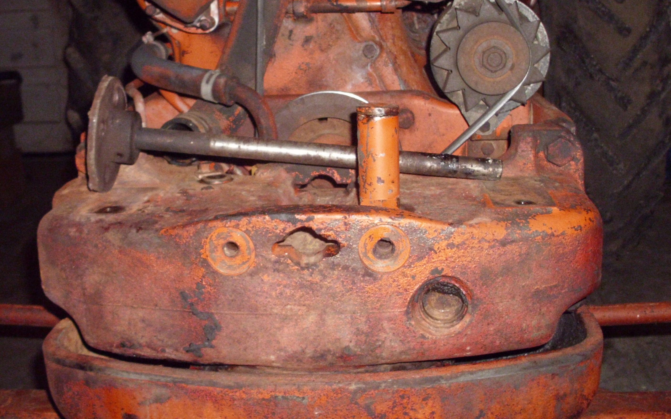 The shaft sitting on top is from an aftermarket kit that uses a 3/4" keyed shaft to a 4-bolt coupler, and the other end goes to a U-joint connected to a pump on a big bracket. There's plenty of room to work and think here... and I think I have a really slick solution. I gotta get this front pulley out, and once it's out, slide in the 4-bolt coupler pulley, but once this one is out, I'm gonna take some measurements, and see if there's a slick way to make a coupling that'll work with a stock 2-bolt setup, in such a way that we don't hafta disassemble anything or fish any crazy tools in there to slip the whole kit in. 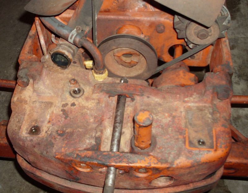
|
Posted By: DaveKamp
Date Posted: 22 Apr 2011 at 3:24pm
 Yes, the shaft is sitting in there backwards. I had it slid in there to get a rough idea of about how far the reach of this other 'kit' was. Hole for the crank is about 1.1", which will be somewhat important later... but not right now. |
Posted By: DrAllis
Date Posted: 22 Apr 2011 at 6:56pm
| That has to be an old D17 ....I've never seen one with a hand crank type pulley. |
Posted By: DaveKamp
Date Posted: 22 Apr 2011 at 7:17pm
|
Yep- it's a Series 1... Haven't checked the serial number, but I think it was about 3 months into production or so. I'll look later and post it. Because of it's condition, and vintage, I'm trying to keep every alteration as reversible as possible. Which leads me to another question- the stock hydraulic fluid storehouse is in the transmission case... what's the fluid capacity in there? And also- the belt-pulley cover holds in hydraulic fluid... if I remove it, is there a good 'view' down to the bottom where I could put a pickup tube (without drilling and tapping a hole in the bottom of the casting?) |
Posted By: junkman
Date Posted: 22 Apr 2011 at 7:21pm
|
My 59 D17 D had one on it. would of hated to use it. never did find where the crank was supposed to hide. |
Posted By: E7018
Date Posted: 22 Apr 2011 at 7:37pm
|
There is room to get the pulley out without moving the front casting forward? Someone put a picture of one of those pulleys on here after you got that first batch of stuff from me. I didn't know there were different pulleys. I figured they all had threaded holes in them. The only hiccup in getting the pulley to you was my daughter's cell phone battery was dead last night. She looked at it the middle of the morning today. The pulley that is coming your way has provision for hand crank. And the threaded holes. |
Posted By: CTuckerNWIL
Date Posted: 22 Apr 2011 at 7:42pm
|
Junkman, On the wall in the corn crib. LOL
------------- http://www.ae-ta.com" rel="nofollow - http://www.ae-ta.com Lena 1935 WC12xxx, Willie 1951 CA6xx Dad bought new, 1954WD45 PS, 1960 D17 NF |
Posted By: junkman
Date Posted: 22 Apr 2011 at 7:44pm
| My book says it holds 2 gal. I have heard of people tapping into it without to much trouble. |
Posted By: DaveKamp
Date Posted: 22 Apr 2011 at 8:00pm
|
E7018- No hiccup- Marshall got it done- it's in my in-laws' car, will be arriving about 2 hours before dinner tomorrow. No way to get it out of there without pulling the bolster- not enough clearance for a puller, and tryin' to lever it out will just bust it up. Whatever I come up with for an improved design, however, will be able to work with either sheave... and able to be installed without taking ANYTHING apart... Dunno how, but I'll think of something. I'll have it all apart and ready when it arrives, buddy will help me get it pushed in, and back together, the one comin' out will be in the box heading your way on Sunday afternoon, and we'll get it figured out from there, thanks!!!! Charlie- Hee hee... yeah, always check the corn-crib wall. When we bought our place, I found all kinds'a stuff there... Hmmm... 2 gallons... good fluid-power engineering practice is to have one gallon of reservoir for every gallon-per-minute of hydraulic flow. That not only assures that you have enough fluid to operate implements, it means you'll have enough expansion room for fluid AND... that your fluid turnover rate will be no faster than once a minute... so it'll have time to cool and shed bubbles on the way. On the low-volume/high pressure lift system, 2 gallons would've been more'n sufficient... but I"m gonna fit a pump that'll swing about 18gpm at full throttle, and be an easy 4-5gpm at idle... guess I'd better find more space... don't think I wanna have any less than 8 gallons on hand, be better to have 10-15 and a good return filter... Any other 'space' in there that I could use? |
Posted By: DrAllis
Date Posted: 22 Apr 2011 at 8:21pm
| 18 GPM is too big......a 6 to 8 GPM pump at 2000 rpm would be more than enough for what you're trying to do. All an 18 gpm pumnp will do is eat up HP. |
Posted By: DaveKamp
Date Posted: 22 Apr 2011 at 8:55pm
|
I'm gonna be running a few things that'll require about 12gpm, and I'd like to do it at about 1200rpm. I'll be running an unloader valve first in line on the stack so parasitic drag will be pretty low. And if you're curious what... it'll be a concrete demolition hammer on the backhoe attachment, as well as a hydraulic firewood processing machine (uses a hydraulically-driven saw, splitter, and log-handling system)... and a 50" side-boom ditch mower... and a hydraulically driven snowblower... kinda volume-hungry machines. |
Posted By: E7018
Date Posted: 23 Apr 2011 at 7:04am
|
"I like machines that are simple, tough, and don't like to wear out. I
also like machines that are really easy to work on, require minimum of
tools and heartache to get apart and together, and use pretty generic
stuff so replacement parts are really easy to find or make." I have watched Jon Kinzenbau for many years, that is pretty well how he got rich. If his designers put in a $600 piece, he will tell them to find something for $30 to do the same job. I put a 30 gpm pump in my D17. (The double section pump with 28 and 32 gpm looked a bit excessive. The early days of ebay.) |
Posted By: DaveKamp
Date Posted: 23 Apr 2011 at 8:35am
|
Hee hee... my cousin Tad works for Jon... Mom's family farm is just north of Marengo... They may 'borrow' an expensive piece to prototype something, then do just what 'ya said- find something 'easier'. They've been known to 'borrow' parts off of other machines to test the protos, then they get put on-task to find a suitable replacement (and put the other thing back together). BTW... it's spelled "Kinzenbaw". I remember riding with Grandpa up to his Ladora shop to get something busted fixed. Funny thing is, Grandpa had a perfectly good welder and outlet sitting in his machine shed... he was deathly afraid of electricity, and my uncle didn't want to learn. Turn the calendar ahead about 15 years, Grandpa gives me the old Lincoln, I took it home, hooked it up, grabbed leathers, shield, and gloves, and started making a metal-mess. Fast forward another 20, and I'm pretty handy with hot-glue... and my cousin's designing the next big blue implement. Kinda cool how things work out. Another note about the pump size... 20gpm IS quite a bit of hog for most guys... but I'm thinkin' ahead. I'm using a 7/8-13 spline on an SAE B interface... that's pretty common, and making an SAE A bracket means just a smaller pilot hole. With splines, I'll get two benefits- First, there's enough slop in a double-ended splined shaft of this length to not need a 'soft' coupling. I'll 'float' mount the pump to take up any deflection. Second, they come apart much easier than a keyed, pinned, or set-screw shaft. It'll only take disconnecting two hoses and two bolts to get the pump out, probably 5 minutes total. By doing this, if I feel the drag of the pump is too high, I can swap the pump with a smaller one, or even just pull out the shaft and run the pump without. I'll also leave enough slack in the lines so the pumpshaft can be pulled without unhooking hoses... and if I can, I'll make the suction tube so that it has to siphon draw a short distance, rather than run full gravity, so that I can unhook a line and lift it a few inches to stop flow. I hate having hydraulic fluid drip all over my shoes and floor... and it's expensive stuff to be losing. |
Posted By: Brian G. NY
Date Posted: 23 Apr 2011 at 9:30am
|
Dave,
I like to improvise.
It looks to me like you might be able to make a puller for your situation by running a long threaded rod thru the crank hole, install a couple of heavy washers and a nut on the front side of the bolster. I also like to use a kingpin thrust bearing to reduce friction.
'course you still gotta figure a way to "latch on" to the pulley in a way that won't take up too much space.
|
Posted By: Gatz in NE
Date Posted: 23 Apr 2011 at 9:44am
|
...the crank ramps are going the wrong direction to DRIVE a shaft; consider the function of them
|
Posted By: Brian G. NY
Date Posted: 23 Apr 2011 at 9:45am
 Maybe something like this? I would use wide rather than thick material to save space.
Just a thought. I'd like to have a nickel for every homemade puller I've built over the years. LOL
|
Posted By: Brian G. NY
Date Posted: 23 Apr 2011 at 10:00am
|
After looking at your pictures for a second time, it looks like there might not be enuf room to pull the pulley as I suggested. However, if there is enuf space to get it started, you might be able to pry it off the rest of the way.
That's if there is sufficient space to even move the pully forward enuf to clear the shaft.
Sounds like you're the type of guy that will figure out something.
We're all rootin' for ya.
I intend to install a front mounted pump on my D-17 but mine is a Series II and has the pulley with the threaded holes so I've got one less hurdle to jump than you.......
|
Posted By: Steve M C/IL
Date Posted: 23 Apr 2011 at 12:28pm
| Them pullys are not interferance fit.Favorite penatrate & air hammer.Remove setscrew first of course.Dad used a crowbar and a BFH back in the day.No keyway either. |
Posted By: DaveKamp
Date Posted: 23 Apr 2011 at 2:02pm
|
Gatz- Yes, they're goin' the wrong way... did someone suggest driving off the ramps? Brian- pulling it isn't a problem, but there's only about 5/8" clearance between end of the flange and the back end of the bolster... and there's well over an inch-and-a-half of purchase on the pulley flange, so no matter how you look at it, either the bolster needs to come out, or the engine needs to come out, in order to get that sheave out. The 4-bolt just arrived in the in-law's car, and the bolster bolts are tight enough to bend a stout box-end wrench, so this is gonna be a challenge to my post-op body. Both the original, and the new pulley are keyway type... and if I remember correctly, my '48 and '39 B and '37 WD are both keyway. |
Posted By: BobHnwO
Date Posted: 23 Apr 2011 at 3:39pm
|
Don't think anyone has addressed pump rotation,looking at the front of the pump I assume you need a pump with CW rotation?
------------- Why do today what you can put off til tomorrow. |
Posted By: DaveKamp
Date Posted: 23 Apr 2011 at 4:31pm
|
Hi Bob! With the pump facing the engine, and the pulley rotation of the engine turning CW, the pump needs to be CCW. |
Posted By: DaveKamp
Date Posted: 23 Apr 2011 at 4:36pm
|
Okay, it took an awesome breaker-bar setup, but I got the front bolster bolts broke loose, and it's sitting on some splitting stands with the front wheels just barely off the floor. I have a 'track' for the axle yoke to lay on, while I slide the whole works forward far enough to swap the pulleys. Now, I need to disconnect the steering shaft. It LOOKS like, to me, that the easiest way to do it on the D17, would be to disconnect it at the joint back on the engine bellhousing. Question is, though... is the pin that holds the yoke in intended to be sacrificial? It looks mushroomed on both sides, so before I start beating on it, or grinding it, I'll check with someone who's done this before... Next... the pivot pin on the axle stabilizer yoke... back under the flywheel... what's the most sensible way to unhook that? I see several bolts, as well as the pivot pin, and don't really see an obvious method for taking that apart in a minimalistic way. Finally, the power steering lines... which ones, and disconnect where, in order to make the least mess? |
Posted By: CTuckerNWIL
Date Posted: 23 Apr 2011 at 4:45pm
I have heard people say the pins are tapered, they are not, at least on the WC and WD. It's a straight nominal size pin with both ends mushroomed into a chamfer. I intended to put roll pins back in the WC but my hired help left the crusty old bolts I stuck in to move it around the shop. Add that to the things to do list. ------------- http://www.ae-ta.com" rel="nofollow - http://www.ae-ta.com Lena 1935 WC12xxx, Willie 1951 CA6xx Dad bought new, 1954WD45 PS, 1960 D17 NF |
 DaveKamp wrote:
Posted By: Claus
Date Posted: 23 Apr 2011 at 5:09pm
| Buy a Series IV or 170, much easier. |
Posted By: E7018
Date Posted: 23 Apr 2011 at 5:16pm
|
The steering shaft on mine had a spline on the front end shaft and a female coupling on the steering housing. Nothing to take apart. All 3 steering lines need to be unhooked. At the front casting. What oil comes out is going to come out. If a person could find a engineering drawing of this piece, it might be useful. http://cgi.ebay.com/Case-IH-Coupling-Coupler-Pump-Drive-A-D140524-480D-4-/290534928592?pt=LH_DefaultDomain_0&hash=item43a53b30d0 |
Posted By: DaveKamp
Date Posted: 23 Apr 2011 at 5:18pm
|
WTH would I want to buy a Series IV or a 170? Well, I wouldn't mind having 'em in my collection, but the Series 1 has an internal meaning to me- it was the very first machine I ever drove, and it connects me to my grandfather, who worked his fields and fed his cattle starting with the WC, then WD, then WD45, then D-17, and the last one was the Two-Twenty diesel with a cab. His D17 Series 1, and the Two-Twenty is still on the family farm, in my uncle's custody. Grandpa's contention was always that, while the Two-Twenty was nice with cab and air-conditioning, good lights and air conditioning, the D17 was twice the workin' machine that the bigger machines were... more compact, and plenty powerful... And anyway, I've got a D17 here, and plenty of capacity to do what I'm doing, so I'll do it, and someday, mebbie I'll have the opportunity to get something else... but not now. |
Posted By: Claus
Date Posted: 23 Apr 2011 at 5:26pm
  Well I owned my late Grandfather's 1964 Series III for about 6 years, it was nice original sentimental tractor for me but I sold it to buy my 170, never looked back but that's just me. Well I owned my late Grandfather's 1964 Series III for about 6 years, it was nice original sentimental tractor for me but I sold it to buy my 170, never looked back but that's just me.
|
Posted By: wfmurray
Date Posted: 23 Apr 2011 at 5:38pm
| Don,t know about D /17 but some of the models have two setscrews. one under one. |
Posted By: pirlbeck
Date Posted: 23 Apr 2011 at 7:17pm
|
Dave,
E7018 is correct, the steering shaft is a splined slip fit where it connects to the coupling on the worm shaft coming out of the bolster. No need to drive out any pins to remove the bolster.
I have removed a lot of these D17 pulleys and the old boy ( long time AC mechanic) that taught me removed way more then I ever will and we never used a puller. Remove (not just loosen) the tapered set screw and drive the pulley off with a long shaft from the bottom. Drive against the meaty part of the pulley and not the back side of the belt groove and it should come right off.
Good luck,
Pat
|
Posted By: Loyd
Date Posted: 23 Apr 2011 at 7:53pm
|
Dave, Do you have a sketch of your final idea? I have a series 1 and would like to do something like you are doing. I also may come up with some ideas. I have been a machinist for over 30 years. I have done machining on F-16, F-18, L-1011, Maverick Missiles and Blackhawk helicopters. Not counting sawmill, concrete and all kinds of other machinery over the years. I may not know much about tractors but I might be able to come up with an idea or two. I also have a cnc plasma machine that is useful for making special brackets etc.. I just reworked a bushhog today for a fellow. I am learning a lot about AC's by reading the posts! Keep up the good work! Loyd |
Posted By: MACK
Date Posted: 23 Apr 2011 at 9:31pm
| Pirlbeck is right. Get the generator out of your way and with a big hammer and a large long punch beat it off. Forget about a puller, it will only cost you when you break your pulley. MACK |
Posted By: Steve M C/IL
Date Posted: 23 Apr 2011 at 11:53pm
| Dad worked on scads of WD's and 45's and a few 17's.Only pulley set up I've seen had tapered set screws.Thats how my 45 is.Not saying yours don't but I've never seen one with a keyway. |
Posted By: DaveKamp
Date Posted: 24 Apr 2011 at 12:05am
Thanks for the helpful hints, guys- yep, the splined steering shaft slid right out, no problem, so one less headache there. I was somewhat foiled by the lower hydraulic line going to the bolster right down by the steering shaft... stuck, and I didn't have a big enough line-wrench, but I noticed that it was clear to move forward if I detached the line at the pump end, and removed one 3/4" headed bolt under the engine mount. The little screw holding the retainer strap was so crammed, in, I couldn't get a wrench on it, so yanking the big bolt was easy and fast. Unhooked the suction line at the pump end, and shoved rubber stoppers in both lines, so it didn't spill much oil. Had a cookie sheet on the floor to catch the dribble, and the frame rail is well lubricated, but all's well.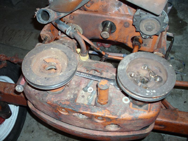 To remove the sheave, I pulled the taper-headed locking bolt totally out as suggested (I'd dealt with these before on my '48 B). I only slid the frontend forward about eight inches, and was able to thread a piece of 1/4" plate with three holes in there, used two bolts through the sheave's bolt-holes, and ran a long fine-threaded rod (actually, the handle to my slide-hammer) in there, just spun the handle to push the pulley off the crank. It wasn't FAST to come off, but it didn't take a scary amount of effort to get it popped loose. 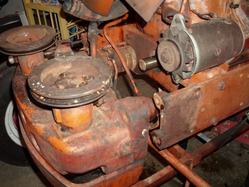 There's about all the farther I had to go to get the old one snuck out, and the new one installed. There WAS a key in the keyway... and it didn't give me a lick'a trouble. To get the new one in, I just started it by hand, wiggled it down 'till it really wanted a rappin', then I put a block of wood on it, stuck a steel rod through the crank guides, and tapped on it with a 4lb machinist's hammer. I was careful to watch the tapered-bolt hole carefully, and stop when I got the crankshaft hole to line up with the bolt. 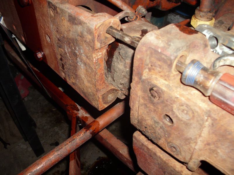 One thing I found somewhat odd, is that the bolster doesn't like to roll straight out of the frame. The steering coupler likes to get hung up on the hole, and the steering ram doesn't clear the frame-rail bosses unless you pull it out cock-eyed. It was somewhat of an exercise of frustration, because I'm limited to 15lbs lifting right now, but doc says I can push, drag, or shove anything I want with my lower body, so I used a couple of ratchet straps, some various metal scraps, etc., to get it slid out, then pushed back in and lined up. |
Posted By: DaveKamp
Date Posted: 24 Apr 2011 at 12:11am
Here's the splined shaft, viewed from below: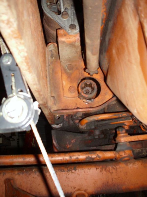 And here's the part I thought would be the most annoying, but turned out to be simple... two bolts holding the axle yoke to the bellhousing... had'ta blast more grime off to see it clearly, and clearly needed some more grime-blasting.  Here's the metal plate I used for pulling the old sheave out:  It was made from junk that was just-lying-around. Actually, it was a shim plate from a scale... I frequently end up with extras... It was made from junk that was just-lying-around. Actually, it was a shim plate from a scale... I frequently end up with extras... |
Posted By: DaveKamp
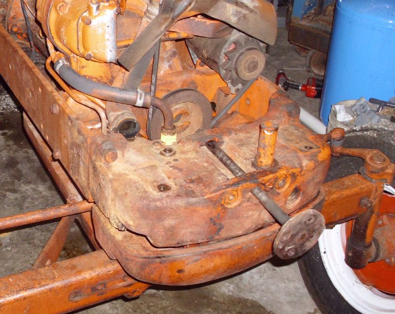
Date Posted: 24 Apr 2011 at 12:16am
And here's the 'new' 4-bolt sheave in place, with bolster ready to slide back into position...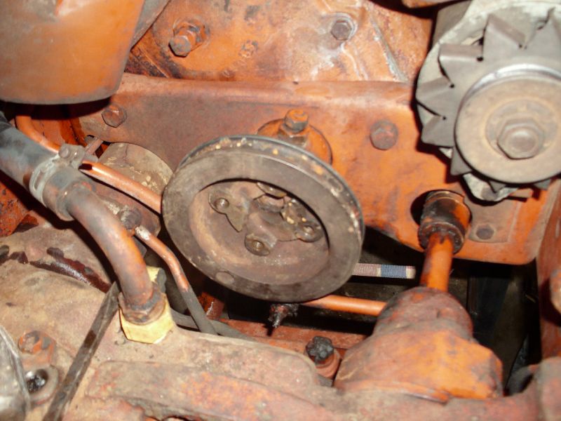 I got it all back in and hooked up, belt back on, etc. I could put the radiator and front shell back in tomorrow, but I'm gonna let it wait 'till Monday evening- gonna pull the thermostat and test it (she doesn't warm up much), flush out the rad, and put it all back together with new hoses. Got family obligations tomorrow, but if there's a break, I'll pull the hand-start B out and reinstall a broken off drawbar... and in the meantime, I'll start fabricating the splined-shaft coupler and front bracketry. |
Posted By: DaveKamp
Date Posted: 24 Apr 2011 at 12:23am
|
Lloyd- I won't have a sketch yet, but I'll probably have one by virtue of making the pieces, and I'll share 'em with anyone who'd like 'em. The CASE/Harvester pump drive coupler is a nice piece- a die-forging, probably. I don't have facilities to do any castings here yet... and will likely never be able to do any die-forging, but I've got about twenty-five machine tools, three torches, and seven welders in my shop, about the only thing I REALLY wished I had, is a CNC cutting table... something I could put a plasma OR gas torch on. I've got about 50% of the parts to build one, but the time, and available shop space aren't there yet... it'll hafta wait 'till the big workshop is done. In the meantime, all the parts I'll use will either be very generic off-the-shelf, or easily fabricated from generic off-the-shelf stuff, so anybody with a lathe and drill press should be able to copy it pretty easily. |
Posted By: Loyd
Date Posted: 24 Apr 2011 at 8:55am
|
Dave, It is looking good! I wish I had 1/2 of the knowledge you have on this stuff. Keep up with the details....I am soaking it up! Thanks, Loyd |
Posted By: Brian G. NY
Date Posted: 24 Apr 2011 at 10:00am
|
Dave, Run by me again how you bolted the puller plate to the old pulley (sheave);
were there holes in it already or did you drill and tap holes?
Any holes in the old pulley are not obvious in your pics.
Maybe I missed something?
|
Posted By: DaveKamp
Date Posted: 24 Apr 2011 at 10:25am
| Dag, Bri- well, 'ya can't see it in the picture, but the early pulley has TWO threaded bolt holes in it. I've got the center dimensions measured, so I can rattle 'em off to 'ya later. I had a pair of bolts that didn't match the threads, but they were slightly smaller and would slip through just fine, and I was able to fish 'em in and thread nuts on the back. The plate is just a flat metal square... I used a dial caliper to find the center distance, drilled the plate, dropped it in there... and just before tightening 'em down, threaded on a piece from my slide hammer to pull against the plate. |
Posted By: DaveKamp
Date Posted: 24 Apr 2011 at 10:27am
|
Lloyd- the fluid power and mechanical engineering, I have plenty of knowledge in... and as much as I've operated a D-17, doing anything other than checking oil was off-limits on Grandpa's fleet... even HE didn't work on his own stuff. (strange, but true)... so there's some workin'-on-it wisdom out there that others have, that I don't have yet... the kinds of things that don't show up in the service manuals, but should... |
Posted By: DaveKamp
Date Posted: 24 Apr 2011 at 8:56pm
| Dennis - the 2-bolt sheave has been transported to my in-law's, house, Marshall will sneak over sometime in the next few days, pick it up from the in-laws, and drop it over where he picked it up... unless you want it somewhere else. |
Posted By: allis restorer
Date Posted: 24 Apr 2011 at 9:11pm
Dave heres a pic of mine i just got done a little while ago putting a pump on my D17 Series 1.  ------------- Go orange or Go home!! |
Posted By: E7018
Date Posted: 24 Apr 2011 at 9:22pm
| Downtown Des Moines any easier? |
Posted By: DaveKamp
Date Posted: 24 Apr 2011 at 10:17pm
| Could- my in-laws live just off the Van Meter exit... Marshall works weekends near the west end of 235... |
Posted By: E7018
Date Posted: 24 Apr 2011 at 10:22pm
|
If Des Moines seems easier, leave it with the receptionist at this place, say "for Clint". http://www.bbsae.com/ |
Posted By: DaveKamp
Date Posted: 26 Apr 2011 at 9:59pm
|
No workshop progress to report, but last Thursday I placed two orders... one from Surplus Center (in Lincoln, Nebraska) for some splined shaft collars and a pump... the other from Steiner Tractor to get an upper and lower radiator hose... was hoping to have 'em show up here around Wednesday/Thursday or so, so I'd be able some wrench and machine-shop time in (fab the coupler, measure the shaft, put the radiator back on, get the tin on, running and operational while I do the 'rest' of the engineering and fab work... Wouldn't 'ya know it... BOTH orders have been sitting... (sigh). Dunno how it works elsewhere, but when an order is placed at my company, it gets processed, pulled, and if it's ready before 4pm, ships the same day... regardless of how flooded we get with shipments... (shrug) So I did something else instead. It DID ease up on the rain for a little bit, but would'a been a good evening to turn wrenches and make metal chips. |
Posted By: Steve M C/IL
Date Posted: 26 Apr 2011 at 11:56pm
| Ordered from S/center 2 weeks ago today(Tues)....they said we're really busy,it'll 4-5 days before we can ship it.Got it the next week on Thursday.Oh well. |
Posted By: BobHnwO
Date Posted: 27 Apr 2011 at 4:48am
|
Dave,what is the number of the pump you got from Surplus Center,Thanks.
------------- Why do today what you can put off til tomorrow. |
Posted By: DaveKamp
Date Posted: 27 Apr 2011 at 7:53am
Here's what I found, but if you're gonna copy my work, don't do it yet- let me 'fall off the horse' first!9-4068-C 2.61 cu in CESSNA 25505LSA HYD PUMP 354.95I'll probably cut one coupler in half, and fit it to a disk to fix to the engine end, and use the other coupler half on a piece of shaft that's been splined at the engine-end. The Cessna pump is a very 'short' package, with ports located on the sides. 2.6ci will give me around 6 and a half gallons/minute at idle. Here's how I figured that out: 1 gallon - 231 cubic inches (remember, the Buick 231 V6 was a 'one gallon wonder') To make one gallon, the 2.6ci pump needs to rotate 231 / 2.6 = 89 rotations... at 89rpm, that's one gallon. Let's say I'm idling at 600rpm... that means I'll be churning through 600/89 = 6.7 gallons. At 1800, I'll be getting 1800/89 = 20. Now, as another noted above, 20gpm is quite a bit. Most guys won't need that much flow... matter of fact, unless you know that you'll be running a hydraulically motor driven load (like a brush, or saw, or auger, or concrete breaker), I'd say size the pump around half that. I chose this size knowing FULL WELL, that I'd probably run that pump only SOMETIMES, and swap to a smaller pump OTHER times. I'll build my whole system assuming 20gpm... hoses, valves... all of it... and if I don't need the capacity, I'll have an identical, but smaller pump... with ADAPTER FITTINGS, so that I can swap in say... a 1ci pump... which will put me at 1 gallon @ 231rpm... or about 3 gallons/minute at 600rpm. Much more reasonable for most uses... throttle it up to 1200, and you'll run a full hydraulic loader nicely. In my case, I'll be running a backhoe that works casually around 4-5gpm, and hard around 8... but a concrete breaker that requires 15 BY ITSELF. Granted, the breaker isn't exactly operating concurrently to swinging the boom, but I do push, lift, hook, and pry while the breaker is running, so NOT having the volume is very frustrating. I operate skid-steers with similar breakers, and they're all running 20gpm or so on the motor circuit, and I over-run them, so I'm certain that if I only fitted my setup for 6-8gpm, I'd be frustrated by slow progress and low power. My other option, would be to have a 'split pump', one high, and one low-volume... but it's added complexity, added drag, and they stick out farther from the front. I want this to be a tidy little setup that doesn't attract roosting chickens, doesn't get banged against things, and LOOKS like it was intended that way... but also... very, very, very easy to work on, and with. |
Posted By: Brian Jasper co. Ia
Date Posted: 27 Apr 2011 at 8:00am
|
Dave, sounds like you have the bolster back on. I was going to say clean any junk out of that splined hole. The input shaft on your power steering valve slides in and out a small amount to function. And for those wondering, the pins for the u joint are tapered. A combination of an air hammer and one of the side frame rails to back up the shaft got the job done. A hand sledge and large punch pretty much just bounced. ------------- "Any man who thinks he can be happy and prosperous by letting the government take care of him better take a closer look at the American Indian." Henry Ford |
Posted By: DaveKamp
Date Posted: 27 Apr 2011 at 11:28am
|
Hee hee... thanks for the tip... but believe it or not, with all the crud I blasted off, that darned socket was somehow devoid of the grime-monster... there was a little I picked out, but most was from me movin' the bolster around. My preferred mode of operation, is to hose everything down good with a pressure-washer before I start. I miss lots of places, so I end up with 'temporary tattoos', but biggest concern is to make it so I can find the darned fasteners, and don't lose grip of my wrenches... keeps me from getting unnecessary dents in my head... keeps the shop cleaner, but no matter how hard I try, there's always something in there somewhere. |
Posted By: sks72107
Date Posted: 27 Apr 2011 at 11:36am
|
Id really like to see some pics of this after completion. I may do it to my series 1 someday, mine already has the 4 hole pulley. great work!!! |
Posted By: BobHnwO
Date Posted: 27 Apr 2011 at 11:36am
|
Dave,Thanks for the info so far and keep riden that horse,lol. ------------- Why do today what you can put off til tomorrow. |
Posted By: Brian Jasper co. Ia
Date Posted: 27 Apr 2011 at 10:03pm
------------- "Any man who thinks he can be happy and prosperous by letting the government take care of him better take a closer look at the American Indian." Henry Ford |
Posted By: JayIN
Date Posted: 28 Apr 2011 at 7:13am
|
Yeah, keep us informed! I was lucky, my D15 already had a front pump on it. ------------- sometimes I walk out to my shop and look around and think "Who's the idiot that owns this place?" |
Posted By: DaveKamp
Date Posted: 29 Apr 2011 at 9:04am
| Well, I'm glad I had everything shipped ground, 'cause UPS's hub got a little plugged-up with the storms. Tracking reports that by end-of-biz today, I'll have the splined couplers, a pump, and upper/lower radiator hoses... I'll put in a little wrench time between now and Sunday so I can get the 17 up and operable... need to drag some stuff off the trailer for a run down to Tennessee on Tuesday... it'll stall my progress for a little bit, but it'll give me time to measure and calculate and order the shaft. Won't take me long to finish up the kit when I return! |
Posted By: DaveKamp
Date Posted: 30 Apr 2011 at 8:38am
|
Okay, got a little done yesterday afternoon and last night: Got the coupler... this fits a 7/8" x 13 spline shaft. It's a little bit long, but I've got a shortener in here somewhere... 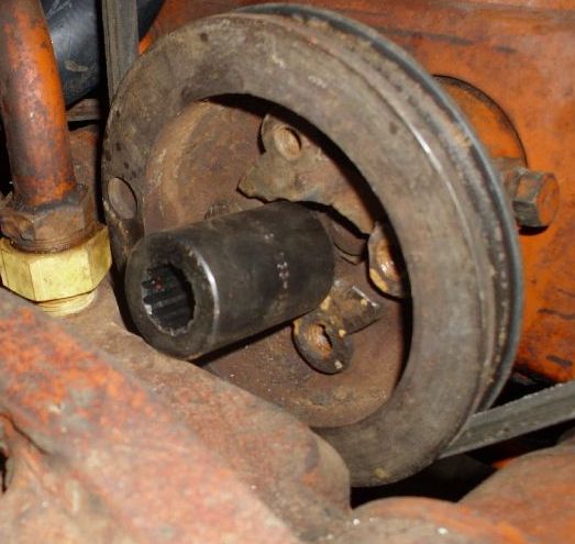 Next: Here's the pump. It's an EATON / Cessna, about 2.6gpm... I posted this, and the coupler part number and source in previous post. 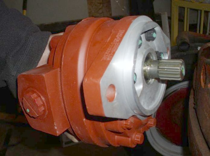 The form-factor of this pump... actually the standard mounting face, is an SAE B 2-bolt mount. The distance between bolt and pilot centers is standardized, as well as hole sizes. There's several different shaft styles that are common to the SAE B, I selected 7/8-13 spline for two reasons- The form-factor of this pump... actually the standard mounting face, is an SAE B 2-bolt mount. The distance between bolt and pilot centers is standardized, as well as hole sizes. There's several different shaft styles that are common to the SAE B, I selected 7/8-13 spline for two reasons- FIRST... it's a common size also used in SAE A pumps (which, for someone wanting less volume, you can simply substitute a smaller pump, and use the SAE A bracket sizing)... and Second, because I"m making this setup so that I can easily pull the pump off, either for service, or to pull the shaft out, thus, removing the engine load when I'm not in need of live hydraulic power. FINALLY, I'm not using a 'soft' coupling or flexible, because I'll be making the mounting arrangement so that the pump is free to 'float', thus, it will WANT to maintain alignment with the crankshaft centerline. There's enough play in the splines (not lots, but enough) so that they'll slip together, and the weight of the pump and plumbing is well within the pump bearings' support capacity, the only thing the bracket will have to do is 1) keep the pump from falling off, and 2) keep it from spinning. Many live hydraulic kits rigidly mount the pump to the frame, and then use flexible couplings at both ends of the shaft. This means the coupling becomes compliant, subject to wear and stress over time, hence, contributory to failure. One of the worst things I can think of here, is having the coupler bolts break off, and having three more in there that I can't back out without taking the bolster off, or worse yet, pulling the engine. Next, I'd hate to hafta try to dismantle it with the pump and plumbing in the way... it'd almost certainly involve applying a cutting torch or sawzall to the shaft to get it out. An IDEAL mounting situation, would be nothing more than sliding the pump onto a coupler right at the crankshaft pulley... and then putting a torque-arm on the pump that keeps the pump from sliding out. Bolster is in the way here, so I gotta 'stretch' it out a bit, which means I'll hafta keep the splined shaft straight, so the pump doesn't 'wobble', but if it does, the mount will allow it... it'll just vibrate alot. Luckily, my coupler-shortner is also a shaft-straightener... |
Posted By: DaveKamp
Date Posted: 30 Apr 2011 at 9:38am
So here, I've used the coupler-shortener/shaft-straightener (also square and oblong roundener, and if I so desire, cam-lobe-maker: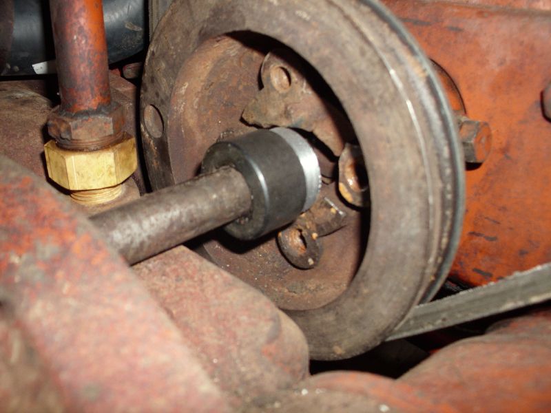 First, I sawed it off with a bandsaw, then I put it in the lathe, and cut it down to appropriate length (trued up the end, 'cause bandsaws ain't known for precision)... then I cut a shoulder in it. I'll cut a plate that fits the hole pattern and fit the coupler in there. Now, for those of you that are machinists, the rest is elementary, but most folks don't have a lathe in their workshop (much less five), so bear with me while I put a little explanation here... The mother of ALL machine tools is the lathe. A lathe holds and rotates a workpiece, while a cutter is put against it. 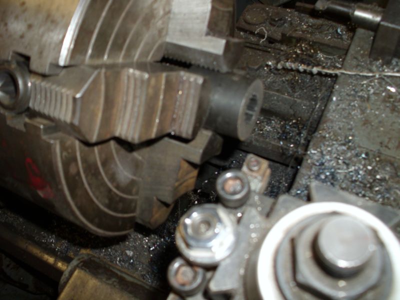 The basic concept is making something round out of something that isn't, but what's REALLY happening, is that you're establishing an AXIS, and then making CONCENTRIC CUTS around it. This is important to remember, and when I make the rest of the coupler, I'll explain not only how I do it, but WHY I do it that way. With ANYTHING, there's always more than one way to get something done... when making precision parts, there's advantages and benefits to every method... but also costs and challenges. Operating machine tools is only a small part operating, and the rest is about thinking ahead so that you do things in an order that make your workpiece more accurate at each step, rather than compound an inaccuracy at each step. In the case of this collar, I put it in the lathe chuck, and used a dial indicator against the OUTSIDE of the collar to get it roughly centered... then I took a piece of shaft material, polished it, and slid it into the splined center, and put the indicator against IT... and adjusted the chuck again. This is because the collar's hole and splines MAY NOT have been concentric to the OUTSIDE in manufacture. These collars are clearly US-made, by a reputable manufacturer, because it was within 0.0004" of concentric. I also checked the amount of 'wobble' at the far end of the shaft, and found that 18" out, it was still under 0.0007", so really danged true. Many (like the imported sheaves and collars found at farm stores and import-tool outlets) are off by lots... 0.004" or more... and they're frequently way out'a square (they'll wobble like crazy 18" out) so if you trust the OD, you're screwed- it never runs true. Here's a quick look at how the pump fits the front of the bolster. In finished form, I probably won't have it recessed that deep, but we'll see what I can do to get it close. I don't like big things hangin' out the front, to get tangled up in stuff.  Notice the direction arrow on the pump? Handy!!! Yes, the crankshaft, when viewed from this end, is spinning clockwise. The pump, since it's FACING the engine, must be the CLOCKWISE type. SOME pumps are reversible... if you're willing to disassemble them and re-orient some components, but many aren't. IF you look in a dismantled pump, you'll see that there's little passages at each end... they go from one side cavity (the high pressure side) to the bearing shell. Then there's oftentimes a passage that goes from the far end of the bearing, to the LOW pressure side. When operating, the pump's output pressure forces oil into the bearing space, to hydraulically 'float' the shaft between bearing and shaft, just like the crank mains and rods of an engine. There's also high-pressure oil forced along the edges of the pump's gears to minimize surface contact force against the sealing face 'wear plates', cooling the gears and minimizing wear. This is one of the first reasons why it is so important to keep hydraulic fluid clean, and level proper to prevent aereation (bubbles). This pump ain't exactly cheap, but it should last my lifetime's worth of abuse with minimal care. There's cheaper pumps out there, and different shapes. I selected it for it's shorter length, side-ports, and robustness. One could use a longer pump, with end-mounted plumbing, but it'd require additional plumbing fittings to reach, and would be very susceptable to pump and plumbing damage. |
Posted By: Nathan (SD)
Date Posted: 30 Apr 2011 at 12:40pm
|
Instead of wasting that good 4 hole pulley. Use your original pulley and just weld your splined stub into the pulley center. You have all the tools to keep it centered and true.
I did it that way to a WD about 15 years ago and it is still going. I had crude tools. I used a 5/8 keyed shaft pump slipped right in the hub and tightened the setscrew. I had a little wobble noticeable at the end of the pump. I made a mounting by the pump flange on one side to hold the pump from spinning. The wobble was not noticeable there so I just sanwiched a rubber washer between the flange and my mounting.
If your are gonna have two splined connections, meaning no set screw anywhere, I think you should have some courser splines in the pulley hub.
I read all your info but didn't see any reference to either end having a setscrew.
|
Posted By: BobHnwO
Date Posted: 30 Apr 2011 at 12:51pm
|
I would weld the coupler to a plate then bolt it to the crank pulley.
------------- Why do today what you can put off til tomorrow. |
Posted By: Nathan (SD)
Date Posted: 30 Apr 2011 at 1:18pm
|
I don't think the bolt holes in the pulley are machined flat. If you bolt the plate in the pulley and then weld the hub to the plate, you will have to make sure the plate goes into the exact same spot any time you disassemble it. A 1 in 4 chance to be wrong. If the 4 holes ARE machined flat then none of this matters and the plate will be fine. |
Posted By: DaveKamp
Date Posted: 30 Apr 2011 at 11:32pm
|
I'll be investigating the hole runout and concentricity thoroughly before committing to it, but I'll make the coupler so that it is dead true, AND if there's a problem with the sheave's bolt heights, I'll come up with a sure way to correct for it. Having splines in the middle of the sheave is an excellent idea, if they would've incorporated it at the factory. The whole idea here, is to establish a very simple, robust, and easy to install drive system, without need to tear the radiator and front bolster out. I've already had to pull the bolster to get the 2-bolt sheave out, and the 4-bolt in. I'm building this setup with the 4-bolt sheave, but eventually I'll be exploring a coupling system for the 2-bolt sheave. Runout at all locations should be expected, and taken into account, however, the best way to resolve it, is to understand how the original sheaves were manufactured. The casting was roughed-in, and then cut, and would've been cut so that all surfaces requiring concentricity, would be cut in a series of operations that never required a change of workholding... example: The sheave bore, the sheave seal OD, the V-belt path and OD, all cut without removing the workpiece from the lathe. This obviously doesn't assure that the workpiece was properly registered to begin with, but if I were the factory machinist, I would have made the workholding fixture so that when installed, the workpiece registered with very predictable results every time. NO set screws- set screws WILL force the shaft to run off-axis, and will not allow it to compensate for relative motion. I'll have just enough compliance in the pump mounting bracket to prevent binding, but little more. |
Posted By: DrAllis
Date Posted: 01 May 2011 at 7:33am
| I'd be very skeptical that the crank pulley itself may not run true. |
Posted By: DaveKamp
Date Posted: 01 May 2011 at 10:38am
| As would I - Allis was incredibly adept at industrial engineering- process, workholding, fixtures and tooling. Making farm equipment was really only a SMALL part of their business, but the key element of all divisions was machine and foundrywork. |
Posted By: DaveKamp
Date Posted: 01 May 2011 at 3:53pm
|
Busy with lots of things today, but I got this far... Found a perfect-sized piece of scrap... had a hole in the middle, so I roughly centered it... 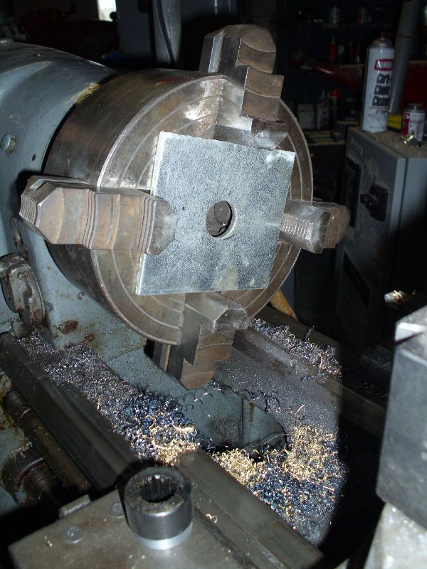 There's the coupler piece down on the apron... So I opened up the hole to proper diameter, and cut a flat area in the face to make the coupler's shaft axis WANT to be perpendicular to the plate... 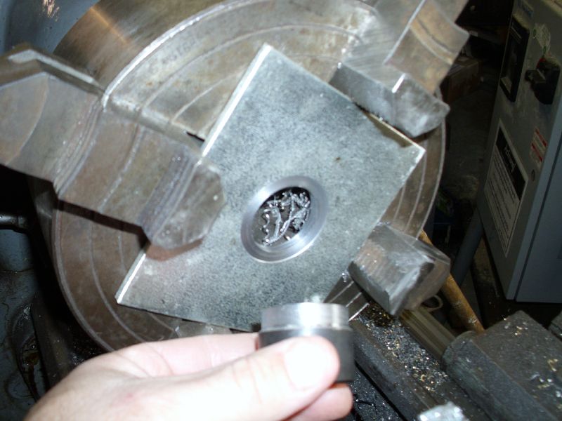 And here it is, installed in plate. 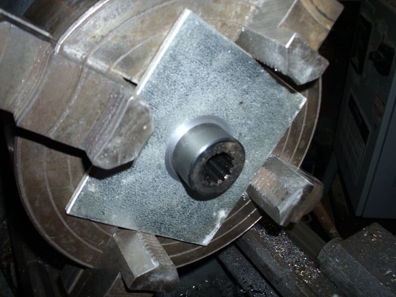 Next, I gotta weld it in. When making precision parts, one often times has to machine parts, then weld them together. Best precision is attained by doing all welding FIRST, and all machining LAST... because welding always results in some type of distortion. IN this case, I had to do first-operation... Fitting up parts that will be welded. Once welded, I'll chuck it back in the lathe, make sure it registers on-center, and then do the final machine-work. This way, I can negate any distortion of the plate or hub alignment by making a skim-cut to correct. I'll also assure that the coupler is round, centered, balanced, and that the hole pattern is properly located. |
Posted By: DaveKamp
Date Posted: 14 May 2011 at 11:13pm
|
Okay, so I had to take a couple of weeks off of shop-time to drive down to Tennessee to install some machines... then race back and bury my grandmother... and things are now getting back to normal, so I spent about half of today in the workshop. So I welded the turned coupler section into the piece of scrap plate. Welding quality, from a cosmetic point of view, was miserable... humidity has been really high, and that box of E7018 soaked it up pretty good... didn't help that my mask needs a new glass, and my right arm is still pretty lame from neck surgery a few weeks ago, but it IS improving: 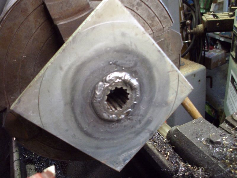 Now, important to note that you always do weldments first, followed by machine work. This way, thermal distortion that occurs, can be corrected by making appropriate skim cuts in machining process. The only exception here, is when you need to use machine tools to FIT UP the parts being welded... which is exactly what I did. Next thing to note- I clamped these pieces together, and tack-welded the BACK side together first... then I allowed it to cool, and checked to make sure that it was actually welded in flush. Typically, when welding, the weld will either PUSH or PULL the parts. In this case, I welded the back, knowing that my tack-welds will PUSH the components together tighter, rather than pull them apart (and not spin true). After tacking from the rear, I welded the front (in 4 beads... two opposites, cool, then two opposites), and then put a bead around the back. Chucked it in the lathe, cut the excess off (to make a round plate, and skimmed the back (where it'll bolt to the sheave) to be totally flat. I used a piece of carefully fitted rod against a dial indicator to make sure that the HUB centerline was concentric to the spindle axis, so that the coupler face would make the splined shaft run true. 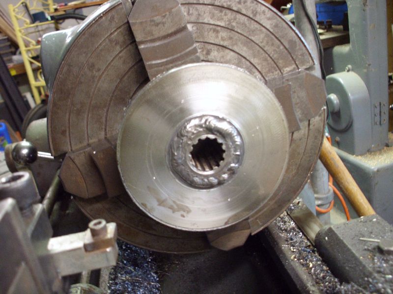 Then I located and drilled holes appropriate for studs into the front sheave... 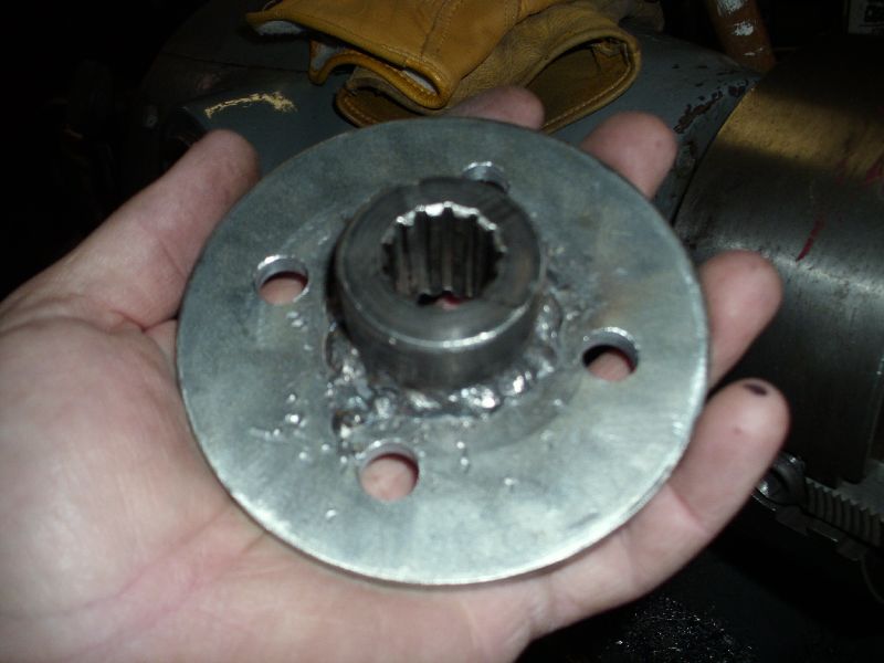 Yep, that's a shameful-lookin' bead, but can't turn back now or re-weld, it'll destroy the work. Plenty strong, so not worried about failure. 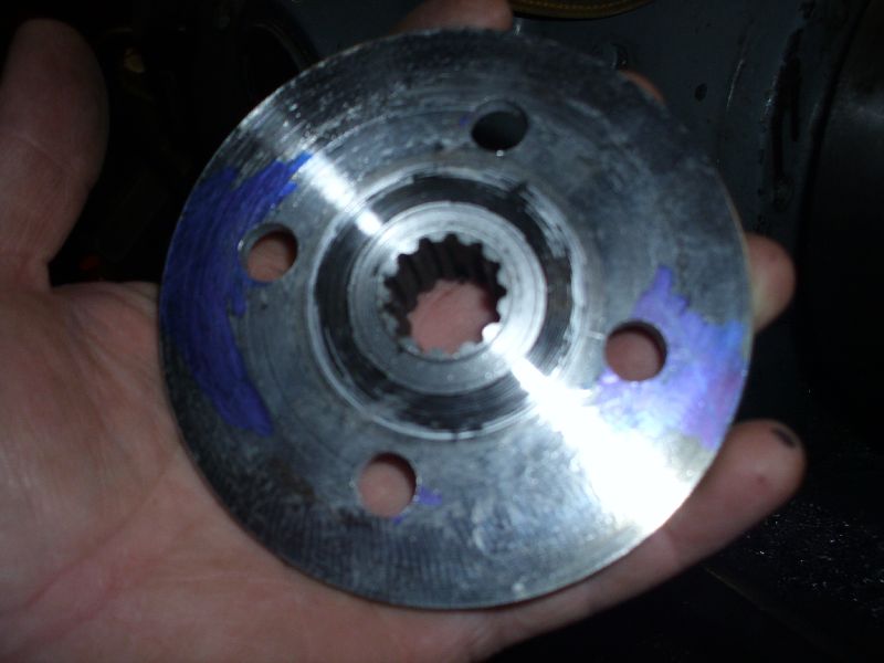 Back side shows the flush/smooth mounting surface, as well as some blue ink left over from locating holes for a-drillin'. Typically, a machinist will use blue dye to make scribe marks very easy to see... but I find that in most cases, all I need is a blue Sharpie... ink the area a little, and hit it with the scribe... |
Posted By: DaveKamp
Date Posted: 14 May 2011 at 11:19pm
Next, is to cut some studs suitable for this setup... I cut some Grade 5 full-thread bolts to appropriate length... 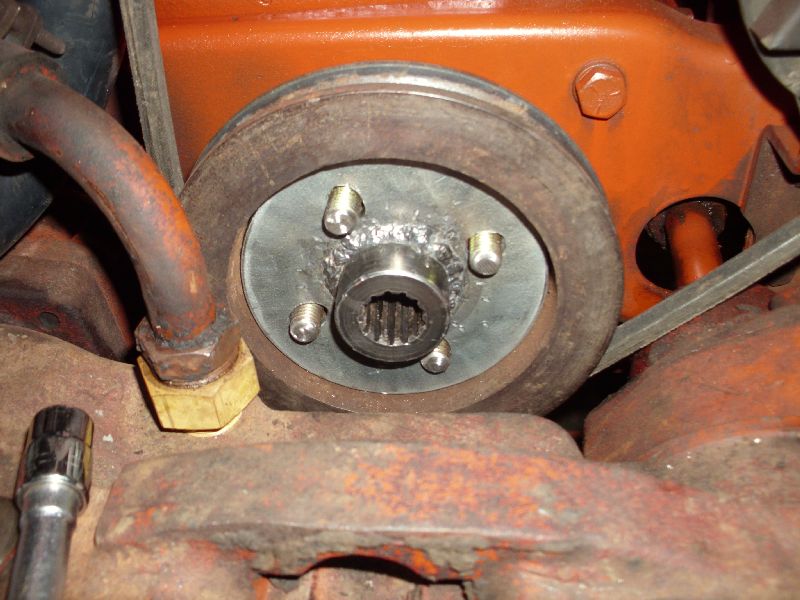 Test fitted everything... then yanked it back out, hit it with some orange paint... then slid back in (and got a grease-smudge on the new paint!) 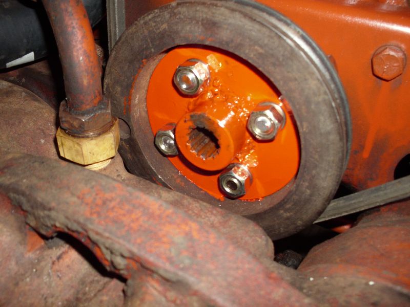 Then I fired it up, and looked at everything spin... and it spun nice and true!!! Reinstalled the radiator shell, 'cause I need to move some stuff around tomorrow, and make a wire-installation plow... then make the front pump mount bracket system... |
Posted By: Jack(Ky)
Date Posted: 15 May 2011 at 7:38am
| I made one like this for Herb (Ga) a couple years ago. I used the 7/8" splined coupling and welded it to a plate and trued it up good on the lathe. The splines seem to have plenty of room to allow for misalignment. His loader had the pump mounted to it so I made the shaft with splines so he could just unbolt the loader and back out of it and the shaft would slip out of the bolster and stay with the pump.JP |
Posted By: Pat the Plumber CIL
Date Posted: 15 May 2011 at 9:49am
|
Thanks for posting pics Dave.Very informative and interesting. ------------- You only need to know 3 things to be a plumber;Crap rolls down hill,Hot is on the left and Don't bite your fingernails 1964 D-17 SIV 3 Pt.WF,1964 D-15 Ser II 3pt.WF ,1960 D-17 SI NF,1956 WD 45 WF. |
Posted By: DaveKamp
Date Posted: 15 May 2011 at 10:26am
|
Cool idea, Jack! One of the things I wanted to accomplish here, was make the coupler so that a guy wouldn't hafta take the radiator and front bolster off to install or change it... and while I installed this with that all off, there is clearance aplenty to do so. The only thing a guy MIGHT run into, is if the sheave bolt-holes were full of crud... he'd have a cussing-circus of cleaning 'em out, but it can be done with patience. Obviously, this coupler layout won't work for an early-style sheave, and I'll dig into that later, but for now, I gotta get this system goin' and get the backhoe mounted and operational. The splines DO tolerate a little malignment... albeit with spline wear. The more-true it runs, the less the splines 'scrub' on the couplers, hence, the longer everything lasts. And there's really two aspects of alignment to focus on... first, making sure that the engine-side coupler runs true to the axis of the crankshaft... you want the centerline of the splined-coupler to be dead true to the crankshaft's axis... you don't want it to be too high, or too low... and you don't want it pointed out at an angle... you want it to be centered and concentric, so that when it spins, you can't see any sort of wobble, even if there's a 1' long shaft sticking out of it. The second aspect, is having the pump lined up with that same axis. The second is fairly easy to obtain once the first has been established... the splined shaft points the way... I'll be getting to that piece next. |
Posted By: E7018
Date Posted: 15 May 2011 at 4:11pm
 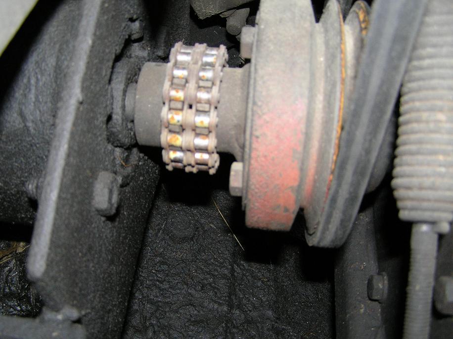  Dave, I have made several of those couplings by making the plate with the bolt holes for the crank pulley and the center hole. Then, fasten it to the crank, mark the position, so it always goes back on the same. Then, weld a stick of threaded bar to something on the tractor so I can fasten the die grinder to the threaded bar and have the cutter in the center hole. Start the engine at idle. With the die grinder "on", move the cutter to the edge of the hole. Grind til it is a perfect circle. Then, make a short piece of shaft in the lathe to just fit in the hole in the plate on one end and the sprocket hub on the other end. Take plate off and put shaft in for welding. After welding, discard piece of shaft. I use a double roller chain for couplings. Dave, I have made several of those couplings by making the plate with the bolt holes for the crank pulley and the center hole. Then, fasten it to the crank, mark the position, so it always goes back on the same. Then, weld a stick of threaded bar to something on the tractor so I can fasten the die grinder to the threaded bar and have the cutter in the center hole. Start the engine at idle. With the die grinder "on", move the cutter to the edge of the hole. Grind til it is a perfect circle. Then, make a short piece of shaft in the lathe to just fit in the hole in the plate on one end and the sprocket hub on the other end. Take plate off and put shaft in for welding. After welding, discard piece of shaft. I use a double roller chain for couplings. |
Posted By: DaveKamp
Date Posted: 15 May 2011 at 6:02pm
|
Yep, in-situ machining on the running engine assures that you'll be concentric... and I've done that trick more than once. Although they're frequently used outside of the range, chain couplers are frequently recommended for use only under 1000rpm or so. Nice thing is that they have a little compliance, easy to make (as long as you have some double roller chain and two sprockets) but they do take up precious space in comparison to a splined-sleeve. Gawd... ain't that weld disgusting? I can't wait to get my right arm strength back... next X-ray appointment is the 23rd... |
Posted By: E7018
Date Posted: 15 May 2011 at 6:26pm
|
That first drive is on my D8 Cat with the 8V71Turbo. Some day, you will have to get by here and drive it in a couple circles. The welding is a bugger with a bad arm. Sometimes, I have to do way out of position welding with my left hand. Way up on something high. I can get it but not well. My daughter is a physical therapist, do your exercises, they work. There isn't room to use a chain coupling on a D17. Even getting the connector link in can be a challenge. Worse than it looks. I try to keep a roll of 60 2 cottered chain around to make couplings. Those couplings seem to stand more misalignment and angle than Lovejoy couplings. |
Posted By: DaveKamp
Date Posted: 15 May 2011 at 9:06pm
|
Yep, and they tend not to break apart as readily as the tabs of a LoveJoy when the rubber isolator spits out. Hmmm... screamin' Jimmy in a D8? I owned a D8 for about 20 minutes once... it's a long, tiring story, but the short of it, was that it had been sitting for 25 years, had a tree growin' through it... but if I could get it started, it was mine. Of course, I got it started... and a neighboring farmer showed up, reminded the owner that he's offered $3500 for it if he could prove it'd start and run... That was a fun day. Never did DRIVE it, but the other farmer did... didn't even worry about the tree... 10" diameter, growin' between the blade and a track... went right over it, busted it off like a twig. Cool machine! Good thing I didn't try to keep it... I didn't have anyplace to PUT it then... Doc didn't prescribe any PT, but I'm a closet kinesiologist, Mom was a PT, then an OT, and I know my anatomy and physiology pretty well. I've been doing full ROM, stretching and light weight routines (limited to 30lbs), and have been getting better, but 2 weeks of having the RH ulnar, radial, and medial nerve cluster clamped between C5 and C6 really put a hurt on my right arm. I'm doing really well in most positions, but some (you mentioned overhead) are really tough... and the only way I've been finding out what positions are weakest... is by seeing really crappy results... holding wrenches, welding stinger... painting... gettin' better, though. Should'a welded that in a rotary table with the MIG... |
Posted By: MACK
Date Posted: 15 May 2011 at 10:08pm
| Easy way to make a front drive for D17 is to make a shaft same size as crankshaft, mount front pulley on shaft anm make it all on the lathe. Made mine from a D17 steering shaft and couppler. Couppler and end of steering shaft are hardened and will last almost for ever. Mine has been on there for 20 years, had it out last winter to rebuild engine. could not see any wear. MACK |
Posted By: DaveKamp
Date Posted: 17 May 2011 at 2:48pm
|
Okay, well, things seem to happen this way... but when I was in there changing everything, I took the time to flush out the engine, change the thermostat (stuck tight!), and rinse out the radiator... and it was pretty yukky inside. After getting the coupler finished, I put it all back together, filled it with water, and run it a bit (to check for leaks). All fine, so I drained and flushed it a little more... drained again... then refilled with a 60/40 mix of ethylene glycol and water. And the radiator sprung a leak. ARGH!!!! Well, it was fixable. Apparently there was just-enough-crud in that one tube to keep it from leaking. I was extra dilligent to flush it out, 'cause I thought I saw a spot down there a while back that was weeping... well, it was. Looks like a piece of something got in there once and nicked a tube... radiator shop boiled it out, fixed the leak, and now she's back together and working. Next step: front pump mount, but before I do that, gotta take a little time-out to fix a neighbor's post-hole auger, drill me a few holes in the yard, pour a little concrete, and build a few other things... gonna do it while I have good sunshine, and come back to this one when we're gettin' rain. Stay tuned! |
Posted By: DaveKamp
Date Posted: 25 Nov 2011 at 11:31am
Yeah, it's been a while, but I HAVE been nippin' away at this project. I got the shaft made... here's what it looked like halfway-done...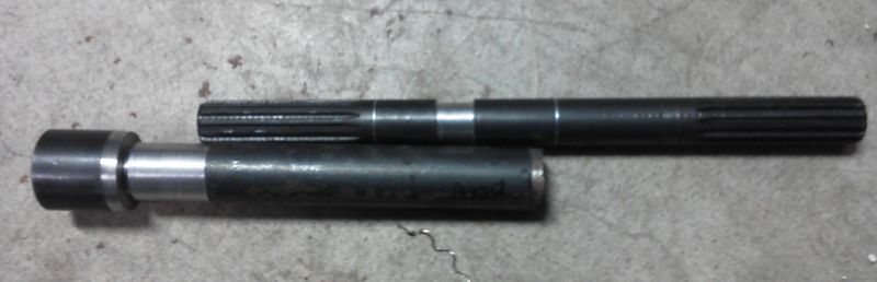 |
Posted By: DaveKamp
Date Posted: 25 Nov 2011 at 1:56pm
|
What I did, in the previous picture... I obtained a PAIR of splined-shaft couplers, and a splined shaft to match the hydraulic pump. These are fairly standard, but apparently not standard enough for a 'stock' shaft length long enough to make the reach from my crankshaft drive to the pump bracket up front. So I took a piece of shaft stock, squared it up in the 4-jaw, and skim-cut one end, then I cut a segment down a bit. Then I cut the coupler a little shorter (short enough so that it would fully engage the pump, of course), and centered it up in the 4-jaw. Gotta note here- the splined hole was NOT concentric to the OD of the coupler, so instead, I put the splined SHAFT in the chuck, adjusted it to run true, then put the COUPLER on the shaft (held it in with the live-center), and skimmed the OD to be concentric with ID. Then I cut a recess in the coupler to be about a thou SMALLER than the OD of the shaft stock. I then put the shaft stock in the freezer, warmed up the coupler, then dropped the two together. Upon cooling, they were not only very, very snug, they were dead-on true. Then I applied a fillet-weld around the outside (with a MIG), and a rosette weld on the inside (with a stick). Chipped out the sl*g and knocked the spatter away, chucked the SHAFT in the lathe, adjusted to run true, then stuck the splined shaft in, put live-center on the far end, and checked to see if it all STAYED true. Rule is, always do all weldments FIRSt, and do machining LATER... well, sometimes 'ya can't... in which case, you always get the welding done, and leave yourself a way to CHECK out the results, and in the event something DOES get stressed out-of-true, you can always SKIM it back into a true state. Next thing I did, was cut the splined shafting to appropriate length, and I turned it to leave about a 3/8" stub out the end 1" or so. I cut the OTHER piece to proper length, and bored a similiar hole, about a thou too small, and shrunk, then welded the two together, then skimmed the whole works down to make a complete unit. Don't see the photo here, so I'll post it later. |
Posted By: DaveKamp
Date Posted: 25 Nov 2011 at 2:18pm
|
In the meantime... I found a hydraulic tank... about 18 gallons or so.
This one has baffles in it, and cleanouts... but interestingly enough,
no suction strainer... instead, it had some sort of clamp-in bulkhead
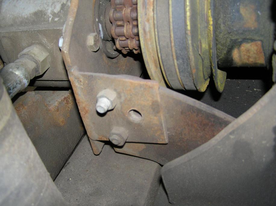
fitting that was long-gone when I got the tank. I ordered a weld-in flange 2" NPT, and a suction strainer 2" NPT outside, and 1.5" ID. I used a hole-saw to open up the original hole, then welded in the flange and installed suction filter. Notice, it's located in a really nice spot- suction line can come forward along the frame rail, into the proper side of the pump (yes, I thought about that beforehand). I made a bracket and tack-welded it to a removable rail (made rails for both sides). I'm still contemplating position here. From a convenience standpoint, this is great- I can reach all the engine service points without removing the tank, and the tank is easily accessable. On the back side of the tank (facing driver) is a combination level and temperature gauge, so perfect. Problem is, it obstructs view to the right-front wheel. I'm not row-cropping, so it probably isn't a big deal, but I DO maneuver into areas where being able to see that front wheel is important. I can stand up in the op position and see the tire, just not while seated. Moving it to the rear will make it so that anything being thrown off the front or rear tires will land ON the tank. Moving it lower will cause it to be hit by the tire when the axle is all the way up (on that side) and tire is turned. I haven't found any other places that are 'better', so without going to a different tank shape, this will probably be it... and I'll probably be mounting an 8D battery on rails on the other side of the tractor to match... we'll see. 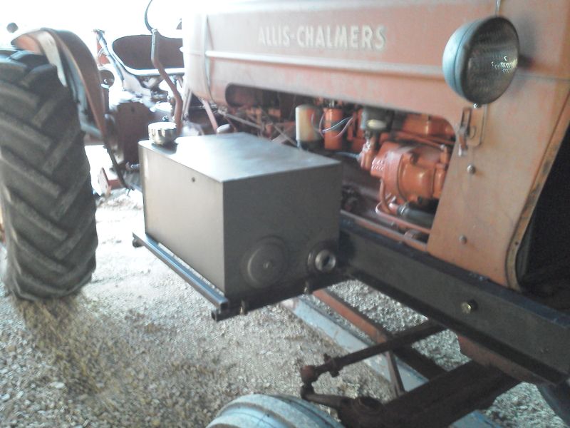 |
Posted By: DaveKamp
Date Posted: 25 Nov 2011 at 2:23pm
| By the way... neck surgery is well-healed, and the arm-strength is back. Really helps when holding a welding electrode. Now if I was only home a bit more often! |
Posted By: DaveKamp
Date Posted: 27 Nov 2011 at 8:10am
Here's the shaft.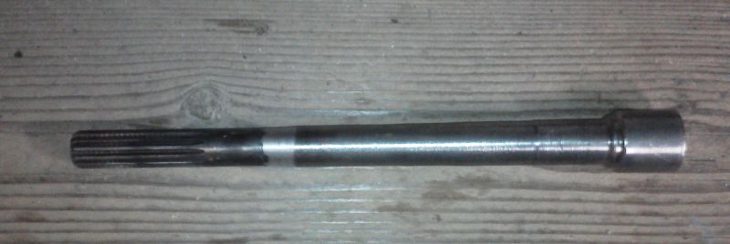 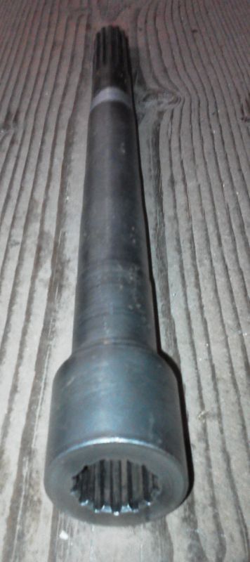 Cool illusion on the second pic- taper in the shaft, and angle makes the image look like it's wider at the top! Pretty simple assembly, really... all it does, is extend the engine's coupler from the engine, to a point in front of the front bolster. When I machined this, I did what any wise machinist would do, and that is, use the splined shaft center as the reference for runout, to make it run true. I used the unused portion of the splined shaft and couplers to MAKE it run true in the lathe, then I made cuts across the OD to yield a 'reference surface' that was concentric to the shaft centerline. This is very important, because these parts frequently aren't concentric... that coupler was clearly a couple thou out on the OD, and the splined shaft was mebbie half that. Get 'em 'phased' right, and the net runout will be very small, but phase 'em wrong, and it's alot of wobble over a foot's span. Now, it doesn't matter which way I install it, it runs dead-true. There's more than enough coupler depth to fully engage the pump's splines, and still leave plenty of room for motion. Need to leave enough slack so that things can flex a bit, even though they really shouldn't. Next, I'll make a bracket to hold the pump that 'floats' with the shaft, but restrains the shaft against torque load, and finally, allows easy removal and installation of this shaft for those times when I don't want the added mechanical load on the engine. Stay tuned! |
Posted By: JK in Pa
Date Posted: 27 Nov 2011 at 8:58am
| Some nice looking machine work there, Dave. I am curious why you are using such a small pump. I installed a vane pump in my WD about Twenty years ago when I built my Backhoe. I used a 12 GPM@ 1200 RPM. Worked out to be the perfect fit. Good Luck. |
Posted By: SenseiCrusher
Date Posted: 27 Nov 2011 at 10:25am
|
http://www.steinertractor.com/ABC1812-front-hydraulic-pump-drive-hub-adapter -
After reading Dave's awesome project I was in the middle of my D17 Series 1 front split and engine rebuild. I looked up an adapter since I did not want to go through all that work (read lazy) and found one that fit perfect.
http://www.steinertractor.com/ABC1812-front-hydraulic-pump-drive-hub-adapter
$42.95 and bolted it on before I reassembled the whole tractor (I have pictures), it fit perfectly.
They also sell 10 spline shafts that can then be cut to length in the future if I go that way and add a front pump.
http://www.steinertractor.com/ABC1814-front-hydraulic-pump-drive-shaft
By the way my pulley already had four tapped holes and they were 7/6-14 NC threads, not 3/8-16.
Thanks Dave for doing this thread, it REALLY got me thinking and I would not have thought to do this without reading your efforts. Looking good Boss!
|
Posted By: DaveKamp
Date Posted: 27 Nov 2011 at 9:41pm
|
JK, sorry- I went back and checked my posting... dunno why I posted 2.6gpm, SHOULD be 2.6 CUBIC INCHES per Revolution. At 1800rpm, that comes out to 20gpm. I WOULD have gone with a vane-pump, but I frequently idle the D17 way down to 'creep' it carefully into position. My Clark IT-60 HAD a vane-pump (and closed-center hydraulics) and regularly shelled out (and seized up) vane pumps, but worst of all, when it was idled-down, it went so slow that the vanes would retract, and there'd be no lift or tilt, no steering (yikes!) and general uselessness of the machine at low speed. My general expectation is, that no matter WHAT I run, I don't think I'll ever run an implement that needs more than 20gpm at 2000psi... and it'd probably be a ditch-mower (flail, etc) or something similar. To get that, I'll be at max goverened speed. When using a log-splitter, or the backhoe unit, I don't think I'll need more than 5-6gpm, so burbling along at 650rpm will be just fine. |
Posted By: DaveKamp
Date Posted: 28 Nov 2011 at 9:38am
|
And Sensei- I looked at the Steiner ref, and it's cool that they have a coupler listed... I found it curious, however, that it didn't list it as fitting the Allis tractors... seein's how it does, in fact, bolt up. Then I looked closer... Your coupler is listed as being a 1" x 20 spline shaft, which is a common standard size for SAE2 and SAE3 hydraulic pumps. I used a less-common standard 7/8 x 13 spline shaft, because it will fit down the center of the stock bolster crank-hole. A 1" shaft won't fit my Series 1 bolster... if I remember correctly, the bolster hole was just big enough for the 7/8" shaft to fit and engage the coupler, and leave mebbie 0.060" 'play' before striking the bolster bore, and a 1" was too big to allow a proper lineup. I sure hope it'll fit yours... |
Posted By: SenseiCrusher
Date Posted: 15 Dec 2011 at 12:55pm
| Hi Dave, I have the project finished, the adapter I bought is for a 1" 10 spline not a 20 spline. The Max shaft OD at the adapter (splines) is 1.0". The adapter bolted right up to the pully. The shaft area where it goes through the bolster is 0.8 inches. The ID clear on my D17 series 1 is 1.30". It fit through with no issues of alignment at all and I can remove it with no problems! |
Posted By: DaveKamp
Date Posted: 17 Dec 2011 at 10:55pm
|
Hi SC! Cool that it all fits! if it's clearing okay, then power to 'ya!!! I"m wondering why Steiner has it listed, but doesn't include the compatibility to AC...??? Between a barrage of business road-assignments, I've been working on my snowblade installation, so haven't made much progress on my live hydraulic setup... but I'll get back to it in a bit. Eventually, my snowblade (a 7.5' Meyer) will lose it's electric hoist/swing system, and get quick-connectors and a lift ram for using the live hydraulic system, but for now it'll be using a battery. Stay tuned! |
Posted By: nsula_country
Date Posted: 25 Apr 2012 at 11:28pm
|
I have a Farmall 504 diesel of 1962 vintage. Early 2nd year. It has a crank pulley that also has hand crank finger bosses. It also has a hole for a crank in the bolster! Who hand cranks a diesel? I feel they were using up old parts at the time! CT ------------- 2014 LS P7010C, 1962 Farmall 504 Diesel (1st tractor) w/ 2008 Koyker 220 FEL, 1968 Allis Chalmers 180 Diesel, Komatsu PC38UU-2 Excavator, Various attachments for all! |
Posted By: Alex09(WI)
Date Posted: 26 Sep 2022 at 9:41pm
|
To make modernizing your tractor easier, we offer these front mounting kits for purchase. No machining required. Make sure your front pulley has provision to bolt adapter hub! Tractors earlier than: D14 engine serial #149-11562/ tractor serial #11476 and D17 gas tractor serial #15931/diesel tractor engine #104840 DID NOT leave the factory with the front pulley that has the 4-bolt pattern for adapter hub. 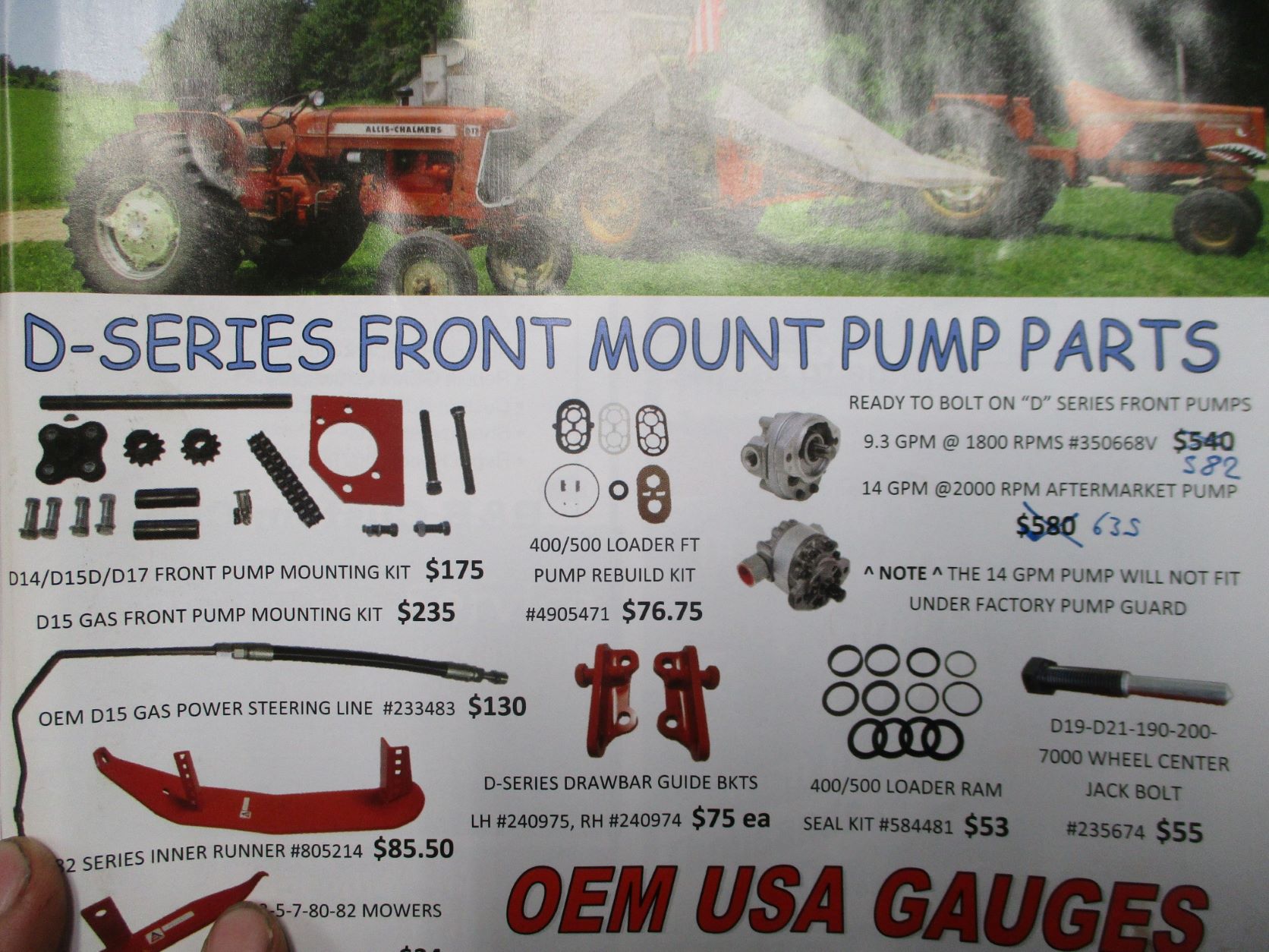 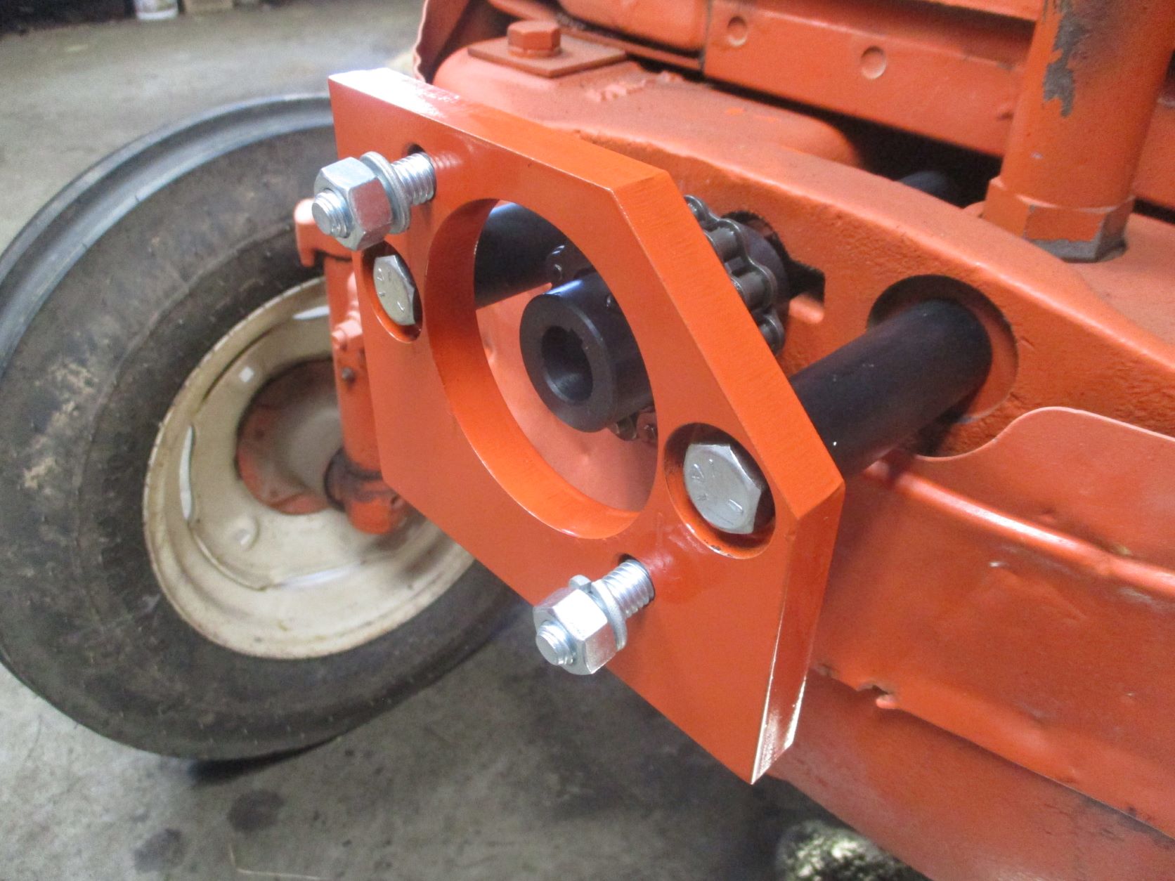 ------------- www.awtractor.com A&W TRACTOR 920-598-1287 KEEPING ALLIS-CHALMERS IN THE FIELDS THROUGH THE 21ST CENTURY |