| Author |
 Topic Search Topic Search  Topic Options Topic Options
|
ssccrab 
Bronze Level


Joined: 12 Jan 2020
Location: KCK
Points: 52
|
 Post Options Post Options
") Thanks(0) Thanks(0)
 Quote Quote  Reply Reply
 Topic: WD45 Ammeter Question Topic: WD45 Ammeter Question
Posted: 19 Jan 2020 at 4:38pm |
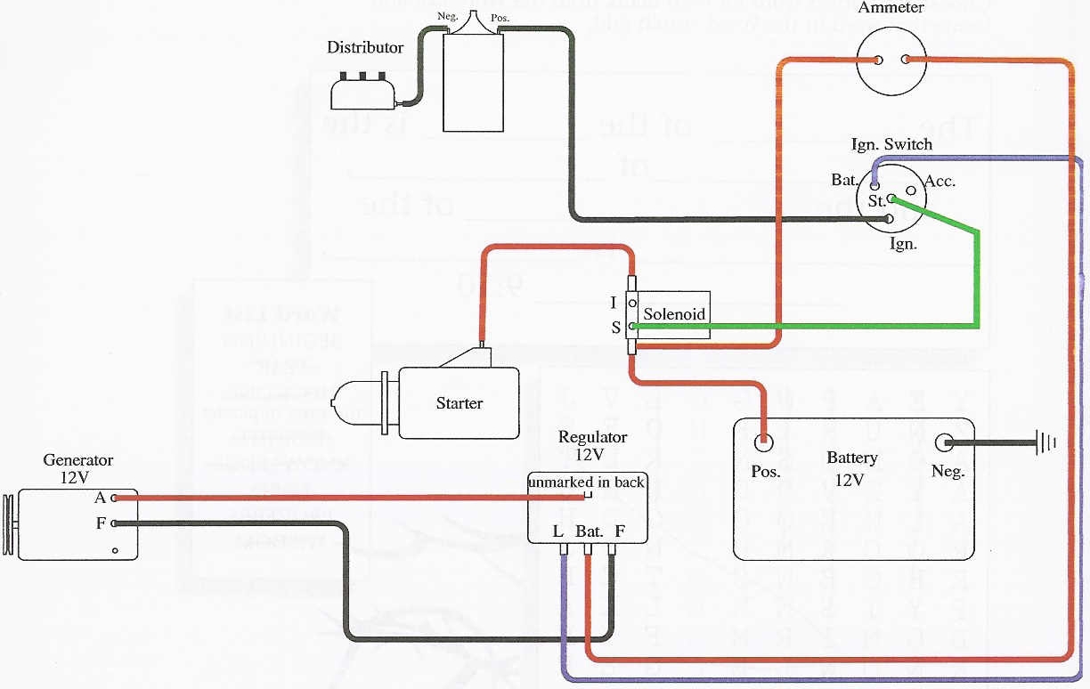
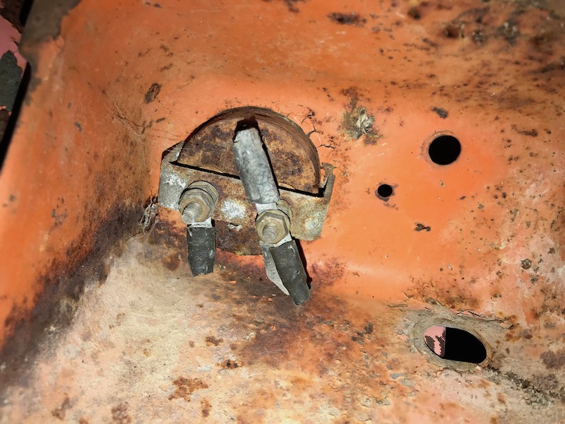
Hey fellas. I'm starting to understand the wiring on this 1955 WD45. Have found a number of wiring diagrams for it. However, I can't understand why this old ammeter would have two or three wires on one post, and one wire on the other. I do have a new one ready to install, just trying to understand the wiring for this so that I can do it correctly. I also just want to make sure this is the correct diagram to go off of. Thanks for your help!
Edited by ssccrab - 19 Jan 2020 at 5:21pm
|
 |
|
Sponsored Links
|
|
|
steve(ill)
Orange Level Access

Joined: 11 Sep 2009
Location: illinois
Points: 90074
|
Post Options
Thanks(0)
Quote Reply
Posted: 19 Jan 2020 at 5:00pm |
|
you can get power at the amp meter terminal to run accessories...might have a head lite wire on it...... the drawing is FINE if you use it.
Edited by steve(ill) - 19 Jan 2020 at 5:09pm
|
|
Like them all, but love the "B"s.
|
|
steve(ill)
Orange Level Access
Joined: 11 Sep 2009
Location: illinois
Points: 90074
|
Post Options
Thanks(0)
Quote Reply
Posted: 19 Jan 2020 at 5:06pm |
|
also your regulator shows 4 wires... some don't have the blue wire to the ignition switch... you might get power to the switch from the common terminal on the amp meter.
|
|
Like them all, but love the "B"s.
|
|
rw
Silver Level

Joined: 28 Oct 2009
Location: United States
Points: 387
|
Post Options
Thanks(0)
Quote Reply
Posted: 19 Jan 2020 at 5:53pm |
|
I think you may need a different drawing. I have a wd, not a 45 but it is six volt positive ground and no solenoid for the starter.
|
|
Sugarmaker
Orange Level
Joined: 12 Jul 2013
Location: Albion PA
Points: 8646
|
Post Options
Thanks(0)
Quote Reply
Posted: 19 Jan 2020 at 7:24pm |
ssccrab, Maybe describe your goal for the electrical system on your tractor? Yes they were originally 6 volt positive ground systems. With 6 volt battery 6 volt gen, voltage regulator and ammeter and lights. And they did not have a selinoid. The pull handle activated the starter switch. Are you looking to go to 12 volt as in the diagram? As far as the number of wires coming off the ammeter. I would agree it could have been a hot wire for something on the tractor. Regards, Chris
|
|
D17 1958 (NFE), WD45 1954 (NFE), WD 1952 (NFE), WD 1950 (WFE), Allis F-40 forklift, Allis CA, Allis D14, Ford Jubilee, Many IH Cub Cadets, 32 Ford Dump, 65 Comet.
|
|
Steve in NJ
Orange Level Access
Joined: 12 Sep 2009
Location: Andover, NJ
Points: 12069
|
Post Options
Thanks(0)
Quote Reply
Posted: 19 Jan 2020 at 8:08pm |
The diagram you're showing is a 12V Negative ground system. If you are going to stay with the 6V PG system, than you need the correct diagram. The original 6V PG system did not incorporate a Voltage Regulator, although a VR would be a nice upgrade for the 6V system. The OEM 6V system used a Reverse Current Relay or better known to the industry as a "cutout". Its only purpose in the system was to sever the Battery from the Gennie, so the Generator wouldn't act as a Dynamo and drain the Battery while the Tractor sits not being used. The OEM system used a multi-function Headight/Charging switch in the dash to increase or decrease the ground at the Gennie for charging.
An Ammeter is a flow meter which means you need to send full current through it in order for it to tell you something. The Ammeter is wired where the Battery is on the + side of the gauge and everything else (accessories) is off the - side of the gauge. On the OEM system, the Headlight charging switch borrowed current from the - side of the Ammeter along with current for the Ignition switch to power up the ignition circuit if Distributor equipped. I offer a complete 6V system for the WD/WD45 if interested. If you are deciding to go with a 12V system, I offer a kit for that to... HTH Steve@B&B bb-customcircuits.com
|
|
39'RC, 43'WC, 48'B, 49'G, 50'WF, 65 Big 10, 67'B-110, 75'716H, 2-620's, & a Motorhead wife
|
|
jaybmiller
Orange Level Access
Joined: 12 Sep 2009
Location: Greensville,Ont
Points: 25083
|
Post Options
Thanks(1)
Quote Reply
Posted: 20 Jan 2020 at 5:40am |
Your picture is the perfect example as to WHY you need to replace the fibre insulating 'washers' on the Ammeter posts ! You can clearly see rust around them,so moistures is /was there. This moisture eventually attacks the fibre washers and a small amount of current can flow from the battery to ground. Once current flows, it gets worse..It may take days or weeks, but ,hmm... battery's dead, arrgh.
When I replaced mine I used Nylon ( plastic) shouldered spacers AND an extra Nylon washer. I also lightly scratched up and painted the new clamp A small amount of never sieze or electrical grease should be used too. Ammeters have been given a bad rap, yet IF properly installed and maintained, they'll do their job for decades.
|
|
3 D-14s,A-C forklift, B-112
Kubota BX23S lil' TOOT( The Other Orange Tractor)
Never burn your bridges, unless you can walk on water
|
|
ssccrab
Bronze Level
Joined: 12 Jan 2020
Location: KCK
Points: 52
|
Post Options
Thanks(0)
Quote Reply
Posted: 20 Jan 2020 at 8:02am |
|
Thank you for the replies and insight. Turns out mine is still on a 6v system, so with everyone's advice here, this should be easy to wire back up. The confusing part was the number of wire on the ammeter, but you guys cleared that right up. I finally found a manual and the wiring diagram inside it. Steve, what did you have to offer on the 6v system?
|
|
Sugarmaker
Orange Level
Joined: 12 Jul 2013
Location: Albion PA
Points: 8646
|
Post Options
Thanks(1)
Quote Reply
Posted: 20 Jan 2020 at 8:59am |
ssccrab, My advice would be to spend the money and upgrade to a new custom 12 volt system. I know a good fresh 6 volt system will work too. But after upgrading all of my W series tractors, the 12 volt system is the ticket. If your current 6 volt system is not in good shape now is the time. Yes you cant follow a factory wiring diagram. But folks on here and Steve can get you through it. Just my 2 cents. Regards, Chris
|
|
D17 1958 (NFE), WD45 1954 (NFE), WD 1952 (NFE), WD 1950 (WFE), Allis F-40 forklift, Allis CA, Allis D14, Ford Jubilee, Many IH Cub Cadets, 32 Ford Dump, 65 Comet.
|
|
jaybmiller
Orange Level Access
Joined: 12 Sep 2009
Location: Greensville,Ont
Points: 25083
|
Post Options
Thanks(1)
Quote Reply
Posted: 20 Jan 2020 at 9:09am |
|
I agree , go 12 volt, negative ground ! Unless you 'have to' keep it original it's the best option. Be sure to replace 100% of the wiring !! ANY old wires WILL cause problems....
|
|
3 D-14s,A-C forklift, B-112
Kubota BX23S lil' TOOT( The Other Orange Tractor)
Never burn your bridges, unless you can walk on water
|
|
ssccrab
Bronze Level
Joined: 12 Jan 2020
Location: KCK
Points: 52
|
Post Options
Thanks(0)
Quote Reply
Posted: 14 Apr 2020 at 9:49pm |
|
Thanks for your advice here, guys. I realized while working on it some weeks ago that the previous owner had switched it over to 12v negative ground, but had the wiring all weird going to what was supposed to be the key switch, which it didn't come with when I bought it. I also found another wiring diagram that was actually right and used it as reference. So I purchased a new ignition switch and ended up replacing all of the wiring everywhere, even down to the headlights. I think I might have the wiring to the ammeter backwards, though. When the alternator kicks in to charge, the needle goes negative. At least I believe it's charging when that happens. No reason to believe it isn't charging, as I've been doing a lot of mowing with it recently and it fires up the first time at every pull. Any advice on the ammeter?
Edited by ssccrab - 14 Apr 2020 at 9:57pm
|
|
Dave(inMA)
Orange Level

Joined: 12 Sep 2009
Location: Grafton, MA
Points: 2399
|
Post Options
Thanks(0)
Quote Reply
Posted: 14 Apr 2020 at 10:54pm |
|
Sounds like the alternator is charging but the ammeter is wired backwards. Try moving the wire(s) from the + terminal to the - terminal and vice versa.
|
|
WC, CA, D14, WD45
|
|
jaybmiller
Orange Level Access
Joined: 12 Sep 2009
Location: Greensville,Ont
Points: 25083
|
Post Options
Thanks(0)
Quote Reply
Posted: 15 Apr 2020 at 5:24am |
Dave's right, you'll need to swap the ammeter wires. Just looking at the picture again, and it's kinda obvious nobody has touched it since it left the factory. You may want to buy a new one first though. Less than 50/50 odds you can sucessfully remove the nuts AND keep the insulating washers in one piece ! Before you try, use a fine wire brush to clean up the studs and nuts. You might get lucky, maybe.....
|
|
3 D-14s,A-C forklift, B-112
Kubota BX23S lil' TOOT( The Other Orange Tractor)
Never burn your bridges, unless you can walk on water
|
|
ssccrab
Bronze Level
Joined: 12 Jan 2020
Location: KCK
Points: 52
|
Post Options
Thanks(0)
Quote Reply
Posted: 16 Apr 2020 at 1:15pm |
|
Thank you all for your replies. I’ll be sure to get those posts switched around. The one in the pic is the original 20-0-20 and I actually didn’t have any difficulty taking it out. The ammeter I have in there now is brand new from the farm store. It’s a 30-0-30 and works well until it jumps backwards at charge, lol. I’ll update here soon as I have the job done!
|
|