| Author |
 Topic Search Topic Search  Topic Options Topic Options
|
Turbo_760 
Silver Level

Joined: 04 Dec 2011
Points: 92
|
 Post Options Post Options
") Thanks(0) Thanks(0)
 Quote Quote  Reply Reply
 Topic: Shimming bearing...confusion Topic: Shimming bearing...confusion
Posted: 31 Aug 2018 at 4:19pm |
|
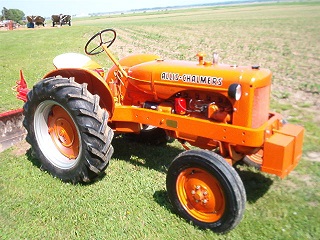
after searching the forms I believe I have an understanding of shimming the rods and Main on my Allis CA. I have a freshly ground crank and new bearings and it is my understanding that I should start with .010 shim pack.
if we start with .010 shim why are all the kits that sold in .004 increment for a total of .008? am I missing something?
I an .080 kit and a few original shim from the engine which I can peel apart for a .0025 shim allowing me to start with .0105 and then check and adjust from there
|
|
1951 CA
Cub Cadet 149
|
 |
|
Sponsored Links
|
|
|
DiyDave
Orange Level Access


Joined: 11 Sep 2009
Location: Gambrills, MD
Points: 54742
|
Post Options
Thanks(0)
Quote Reply
Posted: 31 Aug 2018 at 5:44pm |
Why are hot dogs sold by the dozen, but you get hot dog buns, in 8's? 
The world may never know...
[TUBE]O6rHeD5x2tI[/TUBE]
Edited by DiyDave - 31 Aug 2018 at 5:47pm
|
|
steve(ill)
Orange Level Access
Joined: 11 Sep 2009
Location: illinois
Points: 89313
|
Post Options
Thanks(0)
Quote Reply
Posted: 31 Aug 2018 at 7:57pm |
|
You can try starting with .008 and see what you have. Don't squeeze it down tight right off. Pull it down just snug and see if you can still rotate easy.... If that works, then do the plastigauge and get a reading so you know what thickness to take out. ... an old block can be a couple thousandths out of "STRIAGHT BORE" , so pull each bearing down individually and check when the final shims are in place.. It "can happen" that the center bearing will bindup even with proper clearance if the bore between the 3 bearings is BOWED up or down a thousandth or two.
|
|
Like them all, but love the "B"s.
|
|
WF owner
Orange Level
Joined: 12 May 2013
Location: Bombay NY
Points: 5096
|
Post Options
Thanks(0)
Quote Reply
Posted: 31 Aug 2018 at 9:38pm |
I believe it was DrAllis (or someone else that I have a lot of respect for their opinion) who told me that a freshly ground crank with the right size bearings should get a full shim pack. They were designed so that you could remove shims to compensate for wear. THIS IS FOR CRANKSHAFTS THAT WERE FRESHLY MACHINED ONLY!!! I have installed them, since then, several times. I always check them with plastigauge and they are always within tolerance. When you think about it, I'm sure that's the way they did on the assembly line. They wouldn't have had the time to play with shims on every single engine.
Edited by WF owner - 31 Aug 2018 at 9:40pm
|
|
Alvin M
Orange Level
Joined: 24 Jun 2018
Location: PA
Points: 816
|
Post Options
Thanks(0)
Quote Reply
Posted: 01 Sep 2018 at 9:10am |
|
I Always Get The Block Line Bored So I don,t Need Shims I Do The Same With The Rods Saves A Lot Of Labor Then You Are Right With Specs
|
|
CTuckerNWIL
Orange Level

Joined: 11 Sep 2009
Location: NW Illinois
Points: 22825
|
Post Options
Thanks(0)
Quote Reply
Posted: 01 Sep 2018 at 9:21am |
|
Put a new .008 shim pack in and bolt the cap down without a bearing. Use inside mic or telescoping gauge to check the bore. Check it top to bottom and at least 2 ways at an angle closer to the split in the cap.
I would be willing to bet, your measurements will vary as much if not more than the tolerance for clearance.
What I did on my WC, after I found it .004 out of round with the shims, is to remove .004 shim and use a GOOD Sunnen hone to make the bore round and to the proper size.
Not as good as line boring, but it worked great for me.
The bore, with .010 shim was real close to proper size from side to side, but almost .004 big from top to bottom. Think about how many times that piston fired in the last 50+ years, trying to shove the crank down with each hit. That is why bores are out of round and why line boring is necessary to make things right after years of service.
Edited by CTuckerNWIL - 01 Sep 2018 at 9:23am
|
|
|
|
Gerald J.
Orange Level
Joined: 12 Sep 2009
Location: Hamilton Co, IA
Points: 5636
|
Post Options
Thanks(0)
Quote Reply
Posted: 01 Sep 2018 at 6:22pm |
|
|
|
Turbo_760
Silver Level
Joined: 04 Dec 2011
Points: 92
|
Post Options
Thanks(0)
Quote Reply
Posted: 01 Sep 2018 at 8:34pm |
|
Appreciate all the advice...
I'm going to borrow a bore gauge and check the roundness with .010 shim pack then take it from there. I hope they are round
|
|
1951 CA
Cub Cadet 149
|
|
Dick L
Orange Level

Joined: 12 Sep 2009
Location: Edon Ohio
Points: 5093
|
Post Options
Thanks(0)
Quote Reply
Posted: 02 Sep 2018 at 8:17am |
|
With rods that have not been reworked after 60 years of who knows what they have been thru over the last 60 or so years may not be perfectly round with the .010 shim pack. That does not mean they are not usable. When in design of a shim pack that can have a portion removed to take up bearing wear the designers were not concerned with side wear as removing shims would leave the rod ID oblong to a degree. The .002 clearance concern was only at the point the piston was at top dead center or all the way down. They were not concerned with the side clearance. If the rod was run loose and hammered they may be more out of round than when manufacture. You may not need the full .010 shim in a fresh ground crankshaft and new matched bearings which would not be a problem.
|
|
Turbo_760
Silver Level
Joined: 04 Dec 2011
Points: 92
|
Post Options
Thanks(0)
Quote Reply
Posted: 02 Sep 2018 at 9:45pm |
|
I I haven't picked up a bore gauge yet but I'm eager to get going. I put the . 0 0 8 shim kit in and check the clearances. I wasn't getting a full compression on the green plastic Gage. I switched out the shims and tried a .005 and this brings the clearance down to .0015 on#1 and #2 (haven't messed with 3 yet). however I can feel the resistance with just one bearing torqued. I assume that this might be the result of too much Crush.
Any tips on what to do next?
|
|
1951 CA
Cub Cadet 149
|
|
Dick L
Orange Level
Joined: 12 Sep 2009
Location: Edon Ohio
Points: 5093
|
Post Options
Thanks(0)
Quote Reply
Posted: 02 Sep 2018 at 9:58pm |
|
Not being there it would be my guess that it would be to much crush. The material has to go somewhere and the way I see it, it can only go in.
|
|
Turbo_760
Silver Level
Joined: 04 Dec 2011
Points: 92
|
Post Options
Thanks(0)
Quote Reply
Posted: 02 Sep 2018 at 10:10pm |
|
Is there a way to measure crush with basic tools or is this file a little and test. I assume that I only need to file the 1 bearing. What is the preferred sand paper or a file?
|
|
1951 CA
Cub Cadet 149
|
|
Dick L
Orange Level
Joined: 12 Sep 2009
Location: Edon Ohio
Points: 5093
|
Post Options
Thanks(0)
Quote Reply
Posted: 02 Sep 2018 at 10:32pm |
A few pictures I took when filing and fitting rod bearings. I used a file and used the cap to hold the bearing shell and used a feeler gage to set the edge above the cap to be filed. I didn't guess! https://public.fotki.com/DickL/allis_chalmers_engi/filing-main-and-rod/
|
|
Turbo_760
Silver Level
Joined: 04 Dec 2011
Points: 92
|
Post Options
Thanks(0)
Quote Reply
Posted: 03 Sep 2018 at 8:51am |
|
Thank Dick!
A point of clarification on bearing crush... hypothetically if I had an engine which didn't use shims, the top bearings was flush with the block and the the lower bearing protruded .0015" on both side of the caps.
This would give me .003" crush? This is what I have concluded from my internet research...
|
|
1951 CA
Cub Cadet 149
|
|
Dick L
Orange Level
Joined: 12 Sep 2009
Location: Edon Ohio
Points: 5093
|
Post Options
Thanks(0)
Quote Reply
Posted: 03 Sep 2018 at 12:19pm |
|
I have always gone with .002 to .003.
|
|
wfmurray
Orange Level
Joined: 13 Sep 2009
Location: Bostic NC
Points: 1225
|
Post Options
Thanks(0)
Quote Reply
Posted: 03 Sep 2018 at 12:58pm |
|
Restored my B in 06 and 07.Wanted one to ride around in yard and look at.Not any funds to restore .Had every piece apart except trans and ring gear and pinion.Crank look pretty good and took out shims.Front still a little loose , put piece of drink can under insert and was o k.Got finish mower and have cut over 5 acres several times a year for about 10 years.Cut last week ,good oil pressure runs good and uses no oil.Would not reckamend this but when your poor you do what you can.
|
|
Dick L
Orange Level
Joined: 12 Sep 2009
Location: Edon Ohio
Points: 5093
|
Post Options
Thanks(0)
Quote Reply
Posted: 03 Sep 2018 at 2:34pm |
 wfmurray wrote: wfmurray wrote:
Restored my B in 06 and 07.Wanted one to ride around in yard and look at.Not any funds to restore .Had every piece apart except trans and ring gear and pinion.Crank look pretty good and took out shims.Front still a little loose , put piece of drink can under insert and was o k.Got finish mower and have cut over 5 acres several times a year for about 10 years.Cut last week ,good oil pressure runs good and uses no oil.Would not reckamend this but when your poor you do what you can. |
Back before tag was a pup on old tractors that did not have shims between the rod and rod cap shims could often be found under the bearing shell to reduce clearance.
|
|
Turbo_760
Silver Level
Joined: 04 Dec 2011
Points: 92
|
Post Options
Thanks(0)
Quote Reply
Posted: 05 Sep 2018 at 8:22am |
|
Alright, finally made some progress....
I was able to borrow outside mic's and a 2 point bore indicator. The indicator was setup with gage blocks to the diameter of my crank. I installed the bearings & shims, torque to spec, check with the bore indicator ~.0015" of clearance... perfect. Install the crank, drop some green plastigage on the journal torque and verify it agrees with my measurements.
(only working on #2 main)
I notice that it is difficult to turn. I remove the crank, torque it back with bearings and shims. At ~90 degrees I get the .0015" of clearance. Rotate my Gage to the left clearance starts opening up, rotate to the right past 90 and clearance disappears.
Then it dawns on me that the cap is slightly misaligned, I untorque and push the cap towards the side ( with tight clearance) and verify the that the transition between the bearings are smooth. Repeat measurements and I maintain clearance .
What is the trick to align the main caps as they do not have dowels or any alignment features ( at least #2 which I have been experimenting with)
|
|
1951 CA
Cub Cadet 149
|
|
Dick L
Orange Level
Joined: 12 Sep 2009
Location: Edon Ohio
Points: 5093
|
Post Options
Thanks(0)
Quote Reply
Posted: 05 Sep 2018 at 8:46am |
|
The problem will not end up with cap misalignment of the cap if they are not on backwards. They are offset! I am assuming the rod is in the center of the wrist pin and in the center of the rod journal at the same time. To make sure you are stating the 90º in the same place I am thinking I ask. With the piston down as far as it will go is the clearance at the bottom or the side? At this time look at the bottom of the piston to make sure the rod is in the center of the wrist pin.
Sorry, I did not pick up on you question being on the mains. Mains were not in my mind. The question still stand for the mains. Is the clearance on the side or the bottom?
Edited by Dick L - 05 Sep 2018 at 8:53am
|
|
Turbo_760
Silver Level
Joined: 04 Dec 2011
Points: 92
|
Post Options
Thanks(0)
Quote Reply
Posted: 05 Sep 2018 at 8:56am |
|
Dick,
I am talking about the crankshaft and main bearing cap as that is all that I have installed. The main bearing cap does not have dowells and there is slop in the bolt holes which allows you to push the cap towards either side of the block creating a misalignment between the upper and lower shell.
|
|
1951 CA
Cub Cadet 149
|
|
Turbo_760
Silver Level
Joined: 04 Dec 2011
Points: 92
|
Post Options
Thanks(0)
Quote Reply
Posted: 05 Sep 2018 at 8:59am |
Dick L wrote:
The problem will not end up with cap misalignment of the cap if they are not on backwards. They are offset! I am assuming the rod is in the center of the wrist pin and in the center of the rod journal at the same time. To make sure you are stating the 90º in the same place I am thinking I ask. With the piston down as far as it will go is the clearance at the bottom or the side? At this time look at the bottom of the piston to make sure the rod is in the center of the wrist pin.
Sorry, I did not pick up on you question being on the mains. Mains were not in my mind. The question still stand for the mains. Is the clearance on the side or the bottom? |
If the cap is aligned then I have clearance all the way around. However, if I just bolt the cap down and do not make an attempt to center it then I run into issues. Without the crank in the is easy to do. From my measurement I know which way to push the cap before I torque it. Just curious if there a way to align them or a feature that I am missing on my block/mains which aligns the main cap.
|
|
1951 CA
Cub Cadet 149
|
|
Dick L
Orange Level
Joined: 12 Sep 2009
Location: Edon Ohio
Points: 5093
|
Post Options
Thanks(0)
Quote Reply
Posted: 05 Sep 2018 at 9:02am |
Here is a chart that gives the clearances from .001 to .002. Your .0015 is right in the center and should be fine. I have found over the years that I use .002 or slightly over because of the problem you are having. 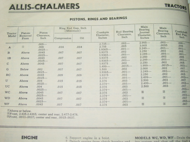
Edited by Dick L - 05 Sep 2018 at 9:02am
|
|
CTuckerNWIL
Orange Level
Joined: 11 Sep 2009
Location: NW Illinois
Points: 22825
|
Post Options
Thanks(0)
Quote Reply
Posted: 05 Sep 2018 at 2:13pm |
|
The shoulder on the bolt should be almost press fit, meaning you need to tap the bolt in to get it in the hole. If you have slop in the fit between the hole and the bolt, something isn't right.
|
|
|
|
Tbone95
Orange Level Access
Joined: 31 Aug 2012
Location: Michigan
Points: 12337
|
Post Options
Thanks(0)
Quote Reply
Posted: 05 Sep 2018 at 2:17pm |
Alvin M wrote:
I Always Get The Block Line Bored So I don,t Need Shims I Do The Same With The Rods Saves A Lot Of Labor Then You Are Right With Specs |
What's With All The Capitalized Words? That's Weird And A Bit Annoying! 
|
|
Dick L
Orange Level
Joined: 12 Sep 2009
Location: Edon Ohio
Points: 5093
|
Post Options
Thanks(0)
Quote Reply
Posted: 05 Sep 2018 at 2:54pm |
|
In normal assembly when the cap is put on with the bearing shells installed over the main journal it is self aligned and not a problem.
If it was torqued without shims the shell could be distorted enough for it to be tight on the sides. You should be able to set the crankshaft down in the block with the shells in place and check both sides of the journal at the shell ends to see if you have clearance or if the shell ends have pulled in. If the babbit has became thicker because of over crushing the ends you could check thickness with knife edged calipers at the bottom or center of the shell and at the ends. If you find it to be thicker on the ends at the edge. This would be the only place on a bearing shell you would dare remove material with a fine file. Any other place on the inner bearing shell I would ever touch even with my fingers without dripping in oil.
I wouldn't assume what I laid out was your problem but where to check.
These Allis Chalmers engines have a less than precisions made bearing caps compared to auto engines.
Edited by Dick L - 05 Sep 2018 at 2:57pm
|
|
Turbo_760
Silver Level
Joined: 04 Dec 2011
Points: 92
|
Post Options
Thanks(0)
Quote Reply
Posted: 05 Sep 2018 at 9:07pm |
CTuckerNWIL wrote:
The shoulder on the bolt should be almost press fit, meaning you need to tap the bolt in to get it in the hole. If you have slop in the fit between the hole and the bolt, something isn't right.
|
I wonder if I have the wrong Main bolts? This engine was rebuilt in the past and perhaps the ones that I have are not correct. The the shank and the bore of the cap have plenty of clearance. They are not a tight fit like the connecting rods  The bolt hole do have a chamfer  No shoulder on the bolts 
|
|
1951 CA
Cub Cadet 149
|
|
Dick L
Orange Level
Joined: 12 Sep 2009
Location: Edon Ohio
Points: 5093
|
Post Options
Thanks(0)
Quote Reply
Posted: 06 Sep 2018 at 11:49am |
That is the way they all are! 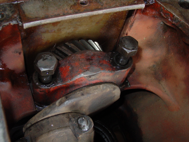
|
|
Dick L
Orange Level
Joined: 12 Sep 2009
Location: Edon Ohio
Points: 5093
|
Post Options
Thanks(0)
Quote Reply
Posted: 06 Sep 2018 at 12:02pm |
I don't know if it will help you at all but your welcome to go thru the many pictures I have taken of these engines in stages of rebuild at the links. The pictures are not well organized so you would have to pick out the album names the would be of interest. https://public.fotki.com/DickL/allis_chalmers_engi/allis-chalmers-c-st/https://public.fotki.com/DickL/
|
|


