| Author |
 Topic Search Topic Search  Topic Options Topic Options
|
Dean (West MI) 
Orange Level


Joined: 12 Sep 2009
Location: West Michigan
Points: 1282
|
 Post Options Post Options
") Thanks(0) Thanks(0)
") Quote Quote  Reply Reply
 Topic: Hooking up a 4 post ignition switch? Topic: Hooking up a 4 post ignition switch?
Posted: 27 Jun 2015 at 7:12pm |
|
I'm rewiring a 12V, negative ground, alternator D15. The ignition switch has for terminals. They are labeled, "IGN, ACC, BAT", the fourth terminal is on the very back of the switch and isn't labeled. I think the unlabeled terminal may go to the starting solenoid and only be active when the key is held all the way to the right.
What terminal would I hook the coil, light switch, and the wire coming off the positive side of the ammeter?
Also, the tractor has a Hobbs electric hour meter with two spade terminals. I imagine one wire would go from a ignition switch terminal (which one?) To one spade, but what hooks to the other spade?
|
 |
|
Sponsored Links
|
|
|
Adam Stratton
Orange Level Access
Joined: 11 Sep 2009
Location: SW MO
Points: 1363
|
Post Options
Thanks(0)
Quote Reply
Posted: 27 Jun 2015 at 11:07pm |
|
I think youre right about the solenoid. I would hook the ammeter and light switch to the bat terminal, the coil to ign, and you shouldnt need the accessory terminal, but if will act similar to the ign term (on when switch is on, off when off). The hobbs meter should have a positive and negative terminal, so you could hook the positive to the acc or ign terminal, and ground the other. I think.
|
|
Gary
Orange Level Access
Joined: 13 Sep 2009
Location: Peterborough,On
Points: 5911
|
Post Options
Thanks(0)
Quote Reply
Posted: 28 Jun 2015 at 5:10am |
|
Have a look at this diagram
Gary
http://dueyschutter.freeservers.com/cgi-bin/i/images/1_distributor_key_solenoid_start_6_to_12.jpg
|
|
jaybmiller
Orange Level Access
Joined: 12 Sep 2009
Location: Greensville,Ont
Points: 25242
|
Post Options
Thanks(0)
Quote Reply
Posted: 28 Jun 2015 at 7:36am |
|
ACC terminal only gets power when the key is in the 'on' or 'acc' position NOT in the 'start' position.
IGN gets power in 'on' and 'start' positions.
BAT obviously goes to the BATtery..through the ammeter.
I'd hookup hour meter on the IGN connector, lights to the ACC connector.
hour meter will have + and - terminals, -ve to ground, +ve to power.
Jay
|
|
3 D-14s,A-C forklift, B-112
Kubota BX23S lil' TOOT( The Other Orange Tractor)
Never burn your bridges, unless you can walk on water
|
|
Steve in NJ
Orange Level Access
Joined: 12 Sep 2009
Location: Andover, NJ
Points: 12071
|
Post Options
Thanks(0)
Quote Reply
Posted: 28 Jun 2015 at 8:38am |
|
Be careful. Some Ignition switches that have a terminal NOT MARKED may be a grounding terminal for the Switch! Most key crank start switches are labeled "ST" for Starter next to the terminal like the others are marked. Watch using an Ammeter with an Alternator. For safety you should be using a Voltmeter. This way in case there's a problem on board in the electrical department, you don't burn the Tractor down.
Steve@B&B
|
|
39'RC, 43'WC, 48'B, 49'G, 50'WF, 65 Big 10, 67'B-110, 75'716H, 2-620's, & a Motorhead wife
|
|
Gerald J.
Orange Level
Joined: 12 Sep 2009
Location: Hamilton Co, IA
Points: 5636
|
Post Options
Thanks(0)
Quote Reply
Posted: 28 Jun 2015 at 10:17am |
|
But the voltmeter gives way less useful battery charging information compared to the ammeter.
Gerald J.
|
|
jaybmiller
Orange Level Access
Joined: 12 Sep 2009
Location: Greensville,Ont
Points: 25242
|
Post Options
Thanks(0)
Quote Reply
Posted: 28 Jun 2015 at 10:35am |
|
If you really want to be 'safe' you need to install a properly rated fuse in the circuit AND have a 'battery disconnect' switch as well.
Re: the voltmeter vs ammeter battle...
An ammeter will tell if a charge is actually going into the battery, a voltmeter won't. Just cause the voltmeter says '14 it doesn't mean electrons are going into the battery! been down that road a few times...
The 'problems' I've seen with ammeters is 'reusing' an old one without replacing the insulators on the terminals. Those should be replaced with nylon units NOT reusing the 50 year old 'fiber' ones. Correctly installed and wired, ammeters will easily give you 40-50-60 years of service.
Jay
Jay
|
|
3 D-14s,A-C forklift, B-112
Kubota BX23S lil' TOOT( The Other Orange Tractor)
Never burn your bridges, unless you can walk on water
|
|
Dean (West MI)
Orange Level
Joined: 12 Sep 2009
Location: West Michigan
Points: 1282
|
Post Options
Thanks(0)
Quote Reply
Posted: 28 Jun 2015 at 9:47pm |
Thanks everyone for all of the help, the new wiring harness made from scratch is working! I could never have done this without everyones input. I still have to run wire for the fender lights, but first, I have to finish the body work and painting for the fenders.
Sadly, it looks like the Hobbs hour meter turned for the last time. It ran until the next number came up and then stopped. Now all it does it click for 20 seconds and then falls quiet. Stopped at just under 3,000 hours. :-( Oh well, with the exception of the Hobbs, all the other gauges are new.
Edited by Dean (West MI) - 28 Jun 2015 at 9:49pm
|
|
MACK
Orange Level
Joined: 17 Nov 2009
Points: 7664
|
Post Options
Thanks(0)
Quote Reply
Posted: 28 Jun 2015 at 10:03pm |
|
The ammeters made 40-50-60 years ago may last that long, but don't expect one made today to last that long unless you leave it in the box it came in. MACK
|
|
DiyDave
Orange Level Access

Joined: 11 Sep 2009
Location: Gambrills, MD
Points: 55276
|
Post Options
Thanks(0)
Quote Reply
Posted: 29 Jun 2015 at 5:02am |
|
Hour meter should be marked + and - . + goes to switch
|
|
Steve in NJ
Orange Level Access
Joined: 12 Sep 2009
Location: Andover, NJ
Points: 12071
|
Post Options
Thanks(0)
Quote Reply
Posted: 29 Jun 2015 at 4:59pm |
|
I didn't want to hurt the Jaybirds feelings, but them days are loooong gone something lasting that long. Good one Mackster! As long as its in the box its fine...
|
|
39'RC, 43'WC, 48'B, 49'G, 50'WF, 65 Big 10, 67'B-110, 75'716H, 2-620's, & a Motorhead wife
|
|
jaybmiller
Orange Level Access
Joined: 12 Sep 2009
Location: Greensville,Ont
Points: 25242
|
Post Options
Thanks(0)
Quote Reply
Posted: 29 Jun 2015 at 5:33pm |
|
Hay guys have some fun, I can take it ! Just be nice to STOP raining for a few days!!
As far as gauges go maybe i shouldn't say I have an all digital dash for my D-14 on the drawing board. If it keeps raining I might just build it...
Has ammeter, voltmeter, tach, oil press, h2o temp ,etc.
Jay
|
|
3 D-14s,A-C forklift, B-112
Kubota BX23S lil' TOOT( The Other Orange Tractor)
Never burn your bridges, unless you can walk on water
|
|
Joe in Manty
Bronze Level

Joined: 08 Apr 2014
Location: Manitowoc, WI
Points: 48
|
Post Options
Thanks(0)
Quote Reply
Posted: 23 Mar 2016 at 10:26pm |
Guys,
Looking to follow up on this post as I found it searching for "wiring an ignition switch."
Similar situation as stated above. My D15 has been converted from generator to alternator. A previous owner had removed all of the original wiring and replaced it with ALL red wire of various gauges!! A lot of BAAAD connections! The original switch was changed out to an off-the-shelf model.
I pulled out all of the existing wire and started new. With 17 years at a wiring harness manufacturer, I began rebuilding the harness, following the wiring diagram in the op manual and routing all the wires by their correct colors and connections.
Now, in matching the old switch to the new INDAK model, I am stumped by one connection. There was a wire routed from the ammeter to the BAT terminal on the switch. I don't see that connection on the wiring diagram but that shows a diagram for a generator.
The tractor was running when I bought it. I just have been replacing and repairing items. Now I am at the point of finishing the wiring part before firing it up again.
Any help is appreciated.
Joe
|
|
Steve in NJ
Orange Level Access
Joined: 12 Sep 2009
Location: Andover, NJ
Points: 12071
|
Post Options
Thanks(0)
Quote Reply
Posted: 24 Mar 2016 at 6:33am |
|
Anything off of the Ammeter should be off the Negative side (-) That would feed your Ignition switch connecting to the BAT terminal. Should have one wire on the plus (+) side of the Ammeter, and that should be your Battery feed in from either the relay or Starter motor. HTH
Steve@B&B
|
|
39'RC, 43'WC, 48'B, 49'G, 50'WF, 65 Big 10, 67'B-110, 75'716H, 2-620's, & a Motorhead wife
|
|
Dakota Dave
Orange Level

Joined: 12 Sep 2009
Location: ND
Points: 3974
|
Post Options
Thanks(0)
Quote Reply
Posted: 24 Mar 2016 at 8:33am |
|
I put 4 post ignition switches in both my C and Ca the unmarked post was a ground for the mag. Usually one with a start position will have start marked next to it. I had bought one for my JD garden tractor and didn't pay close attention. It didn't work wiring harness plugged in but no start. Went to the JD dealer and got the correct one. Only difference was had st marked next to the terminal.
|
|
Dave H
Orange Level

Joined: 11 Sep 2009
Location: Central IL
Points: 3607
|
Post Options
Thanks(0)
Quote Reply
Posted: 24 Mar 2016 at 2:11pm |
My D 15 II has a push button start switch. New wiring harness for it and everything lashed up. 
|
|
desertjoe
Orange Level Access

Joined: 23 Sep 2013
Location: New mexico
Points: 13769
|
Post Options
Thanks(0)
Quote Reply
Posted: 25 Mar 2016 at 4:34am |
Hey Dean and Joe,,,this is what I used on the D15 and the d14. Worked great for me. Hope this helps. 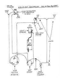
|
|


