| Author |
 Topic Search Topic Search  Topic Options Topic Options
|
Thad in AR. 
Orange Level Access


Joined: 12 Sep 2009
Location: Arkansas
Points: 9733
|
 Post Options Post Options
") Thanks(0) Thanks(0)
 Quote Quote  Reply Reply
 Topic: Hey electricians what are these Topic: Hey electricians what are these
Posted: 19 Feb 2023 at 7:59pm |
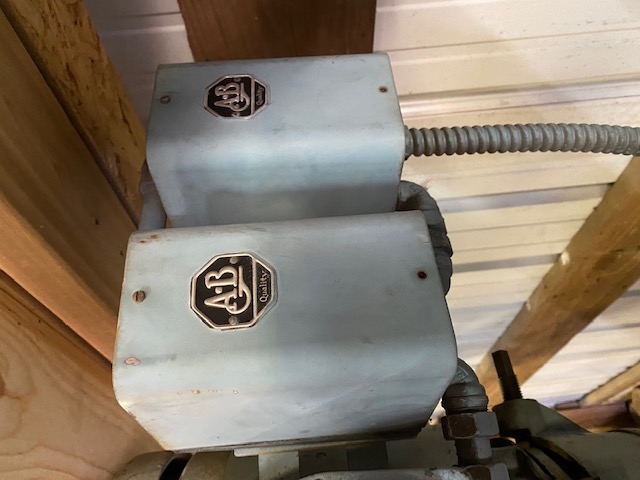
These are on my milling machine. What are they for?  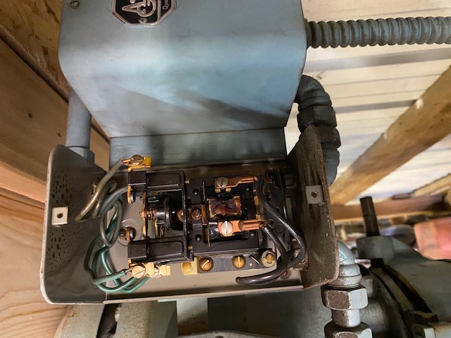
|
 |
|
Sponsored Links
|
|
|
Thad in AR.
Orange Level Access
Joined: 12 Sep 2009
Location: Arkansas
Points: 9733
|
Post Options
Thanks(0)
Quote Reply
Posted: 19 Feb 2023 at 8:00pm |
|
|
|
steve(ill)
Orange Level Access
Joined: 11 Sep 2009
Location: illinois
Points: 90892
|
Post Options
Thanks(0)
Quote Reply
Posted: 19 Feb 2023 at 8:22pm |
Thad, its kind of hard to tell what goes where and where it comes from in the photo... Set of contacters on the top is normally used with a small switch (on - off) to turn on LARGER wires that draw more current.... or could be used on a 3 phase motor to change direction of travel..... Can you trace where the wires on the top come from, where is the Main Power, and where do the two big black wires at the bottom run toward ?
EDIT..... i think the ON (?) switch sends power to the bottom ( black wires) to energize the coil ( single phase, or 1 of the 3 phases) to pull the contactor UP or DOWN... there is probably 3 sets of contactors at the top that connect the wires on the LEFT to the wires on the RIGHT... So it looks like an ON- OFF, 3 phase power to the motor switch.
Since there are TWO BOXES, it could be to run a motor forward or backward.. reverse direction ?
Edited by steve(ill) - 19 Feb 2023 at 9:03pm
|
|
Like them all, but love the "B"s.
|
|
DaveKamp
Orange Level Access
Joined: 12 Apr 2010
Location: LeClaire, Ia
Points: 6126
|
Post Options
Thanks(0)
Quote Reply
Posted: 19 Feb 2023 at 10:04pm |
As Steve says, they're contactors. The contacts are at top, and the coil is at the bottom (black wires). Energize the black wires, and the electromagnet coil on bottom will pull the contacts together.
MOST LIKELY, the two contactors are wired up so that one of them will run motor forward, the other will run it in reverse. There's 3 leads going to a 3-phase motor. Call them A, B, and C. The motor has three leads... call them X, Y, and Z.
Hook up
A to X,
B to Y,
C to Z, and the motor turns in one direction.
Switch ANY TWO wires, and it will run opposite direction... so
A to X, B to Z, C to Y... and so on.
IF There's only two contact sets on the contactors, and it's three phase, there's three leads. The way it works is simple... ONE of the incoming power leads is always connected... let's say A to X.
To make it run one way, B-Y and C-Z To make it reverse, B-Z and C-Y.
In this example, it only takes two contactors, each having two sets of contacts. When ONE contactor pulls in, it makes the B-Y and C-Z connection. When the other pulls in, it makes the B-Z and C-Y connection.
Your switch, therefore, needs to just connect control power to one contactor, or the other, to get a 'run forward' or 'run reverse' command.
Just gotta make certain that ther's NO WAY that you could ever have BOTH pull in at the SAME TIME... they have to be mutually exclusive, lest you have B shorted to C.
BTW... a contactor is oftentimes referred to by some as a 'relay'... and while they do the same thing, a contactor is different for one very basic reason:
When you energize the coil of a relay, the contacts it controls close... and as long the coil of the relay has power, it will continue to hold them closed. And the relay coil will continue to draw the same amount of power. Let's say the coil of the relay requires 2 amperes to pull in, and once it's in, it continues to require 2 amperes to hold those contacts.
A CONTACTOR, however, is an AC device that, when it 'pulls in', the AC coil's polepiece is 'contacted' by the armature pulling in the contacts. When the armature lands AGAINST the coil's polepiece, two things happen- first is that the armature becomes part of the polepiece's magnetic 'world', and it holds extremely tight, and second, the 'magnetic world' of that armature and coil now 'restrict' the amount of AC current that can flow through the coil... the property is called 'inductive reactance'...
so the end result, is that an AC contactor might require the same 2A to pull in, but once in, the coil naturally LIMITS the amount of current flow through the coil... say... to 1/4A... and as a result, it not only reduces waste energy significantly, it substantially increases the coil's operating life...
IF you come across a contactor that's buzzing when it's pulled in, shut the machine down, carefully disassemble the contactor's mechanism, clean it all up good, especially the pivots and the armature/polepiece faces, and put it back together... it'll pull in solid, get a whole lot quieter, and run cooler.
|
|
Ten Amendments, Ten Commandments, and one Golden Rule solve most every problem. Citrus hand-cleaner with Pumice does the rest.
|
|
steve(ill)
Orange Level Access
Joined: 11 Sep 2009
Location: illinois
Points: 90892
|
Post Options
Thanks(0)
Quote Reply
Posted: 19 Feb 2023 at 10:25pm |
|
the two black wires at the bottom, and from the Second box, should run to a FWD- REV switch..... you "turn on" one of the AB boxes or the other.
|
|
Like them all, but love the "B"s.
|
|
JW in MO
Orange Level

Joined: 16 Feb 2010
Location: Mid Central MO
Points: 2698
|
Post Options
Thanks(0)
Quote Reply
Posted: 20 Feb 2023 at 6:41am |
|
That looks like the set-up I worked on at an old grain elevator many years ago to run the lift for trucks to dump. There was a rotary switch with a little red knob used to activate the up and down.
|
|
Maximum use of available resources!
|
|
Thad in AR.
Orange Level Access
Joined: 12 Sep 2009
Location: Arkansas
Points: 9733
|
Post Options
Thanks(0)
Quote Reply
Posted: 20 Feb 2023 at 6:44am |
|
|
|
Thad in AR.
Orange Level Access
Joined: 12 Sep 2009
Location: Arkansas
Points: 9733
|
Post Options
Thanks(1)
Quote Reply
Posted: 20 Feb 2023 at 6:47am |
|
It has these two switches on the left of the column. Both are 3 way switches.
It also has a switch on the front of the head which I believe is either the spindle foreword reverse switch or it changes the spindle speed. This has a 2 speed motor.
|
|
Thad in AR.
Orange Level Access
Joined: 12 Sep 2009
Location: Arkansas
Points: 9733
|
Post Options
Thanks(0)
Quote Reply
Posted: 20 Feb 2023 at 7:04am |
|
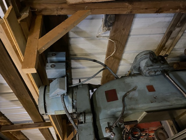
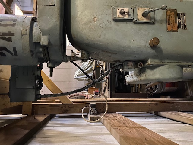
You can see the junction box on the back of the column where the wire is cut. That’s a 4 wire power in.
On the other end of that box is another cut wire that’s a smaller 3 wire in. I assume one for the spindle and smaller for the power feed.
|
|
DaveKamp
Orange Level Access
Joined: 12 Apr 2010
Location: LeClaire, Ia
Points: 6126
|
Post Options
Thanks(0)
Quote Reply
Posted: 20 Feb 2023 at 8:39am |
Okay, so there's 2 speed motors, and there's backgear gearboxes. I wouldn't be surprised if yours has BOTH a 2 speed motor, and a backgear box, but it wouldn't surprise me if it just had one or the other.
A 2 speed motor (aka, a "Dahlander" motor, named for the Swede that invented it) is a 'consequent-pole' motor... it has two sets of windings... basically, it will run in a 2-pole (1 rotation per AC cycle) or 4-pole (1 rotation every two cycles) mode, for (in USA 60hz world) either 3600 or 1800rpm. If it was a really BIG motor, it might run in 4 pole/8pole mode. (I'm not certain wether one could Dahlinder a 4 pole/6pole without using a really huge switch, on account of the crazy contact wiring).
Anyway, the high-low speed setup on a consequent pole requires more than just two contacts to make the motor run, so if you see a contactor or switch with LOTS of contacts right before the motor (and there's lots of wires coming out of the motor) then you have a consequent-wound dual-speed motor. Don't disconnect any of those, it'd be a real challenge to sort them all out in the future (without a diagram, and missing a few wire labels... it'd be a nightmare)...
One thing that may confuse you... on the reversing switch, you MIGHT find that there's another mechanism and switch that reverses the reversing switch... and if so, that mechanism is probably tied into the backgear shift mechanism. Why? Because many backgear mechanisms, in doing what they do, inevitably wind up reversing the spindle direction... so when you throw it into backgear, reverse becomes forward, and forward becomes reverse (Johnny Depp... Captain Jack Sparrow... Down becomes up, and up becomes down, right?) So they put a reverser-reverser in there, so forward is always forward, even when it's reverse.
Are you confused yet? 
Here's a connection schematic that was in a post on PracticalMachinist:
Edited by DaveKamp - 20 Feb 2023 at 8:43am
|
|
Ten Amendments, Ten Commandments, and one Golden Rule solve most every problem. Citrus hand-cleaner with Pumice does the rest.
|
|
steve(ill)
Orange Level Access
Joined: 11 Sep 2009
Location: illinois
Points: 90892
|
Post Options
Thanks(0)
Quote Reply
Posted: 20 Feb 2023 at 8:48am |
Gunna be a tough one without knowing where some of the wires start and end..
I would ASSUME the big 4 wire inlet on the 4x4 junction box on the back, is the 3 phase power INLET....... Then you have a flex cable that goes up to the two AB boxes...So those are probably the 3 phase wires that connect to the 3 contactors in the AB box..
The smaller 3 wires coming out of the 4x4 junction box might be the feed for the table ? You could open the 4x4 box and look and see what they are connected to... Since there is only 3 wires, it may be 2 wires of the 3 phase plus the ground... That means you would have 240 single phase going to the table motor ?? That 240 v single phase could also go to the big toggle switches, and end up being the BLACK wires that turn the electric coils on / off inside the AB boxes..
What is really missing is HOW does the table motor work ? Is there another DC box that controls it ? Is the motor AC or DC ? Is the motor reversable ? You might want to look at the back of the BIG toggle switches and see how many wires each has... You probably going to have to open each box and start drawing a diagram of where the wires start and go..
|
|
Like them all, but love the "B"s.
|
|
Thad in AR.
Orange Level Access
Joined: 12 Sep 2009
Location: Arkansas
Points: 9733
|
Post Options
Thanks(0)
Quote Reply
Posted: 20 Feb 2023 at 9:16am |
|
Steve the power feed motor is 3 phase 1/4 hp.
I assume AC?
|
|
steve(ill)
Orange Level Access
Joined: 11 Sep 2009
Location: illinois
Points: 90892
|
Post Options
Thanks(0)
Quote Reply
Posted: 20 Feb 2023 at 9:20am |
like Dave said, something appears to be missing... If the two AB boxes are fwd- rev... then your missing how you change motor speeds.... If the two AB boxes are for two motor speeds, then you missing the fwd- rev part... There is another contactor box somewhere, or the back of the big switches is VERY complicated ?? ... multiple wires.
i would start by opening the 4 x 4 box and the AB boxes and trying to trace out how the 3 phase inlet wires run up to the AB boxes, and how the two AB box contactors are wired together.... also look at the back of the BIG switches.. how many wires.. etc.
question is WHY was the small 3 wire cable from the 4x4 box cut off ? I would think that would go to the table motor or its switch ?? why cut it off ?
Edited by steve(ill) - 20 Feb 2023 at 9:23am
|
|
Like them all, but love the "B"s.
|
|
steve(ill)
Orange Level Access
Joined: 11 Sep 2009
Location: illinois
Points: 90892
|
Post Options
Thanks(0)
Quote Reply
Posted: 20 Feb 2023 at 9:33am |
|
if the motor says 3 phase, then yes, it is just a 240v AC 3 phase motor.. The question is HOW do you get the 2 speeds.... i would open the elect box cover on the motors and see which conduit all the wires to.... a 2 speed motor would have SEVERAL wires inside that need to be connected in various ways to make the two speeds... If those wires run to the SWITCHES, then the 2 speed is done in that area... from the photos you have, i dont see multiple wires running from the AB box to the motor... that makes me think the AB box is a FWD- REV setup............. and 2 speed is done somewhere else ( on the switch ?)
|
|
Like them all, but love the "B"s.
|
|
Thad in AR.
Orange Level Access
Joined: 12 Sep 2009
Location: Arkansas
Points: 9733
|
Post Options
Thanks(0)
Quote Reply
Posted: 20 Feb 2023 at 10:50am |
|
Only the big motor for the spindle is 2 speed
The power feed is just single speed
|
|
steve(ill)
Orange Level Access
Joined: 11 Sep 2009
Location: illinois
Points: 90892
|
Post Options
Thanks(0)
Quote Reply
Posted: 20 Feb 2023 at 11:45am |
OK... so the spindle motor has an electrical box on it.. Open the lid and there should be 7-9 wires inside... Which conduit do they run to ? If they go to the SWITCH then i would think one of the BIG SWITCHES is doing the 2 speed....and the AB boxes are for the fwd- rev.... If all of the motor wires were running to the AB box, then it could be doing the 2 speed... but i dont see a BIG conduit from the motor to the AB box.
there has to be another conduit box, or a very sophisticated contactor set on the back of one of toggle switches to change the motor speed.. several wires would be involved.
|
|
Like them all, but love the "B"s.
|
|
Thad in AR.
Orange Level Access
Joined: 12 Sep 2009
Location: Arkansas
Points: 9733
|
Post Options
Thanks(0)
Quote Reply
Posted: 20 Feb 2023 at 11:58am |
|
Steve it’s hard to see but the AB boxes have a conduit coming out the bottom and going in the bottom right f the motor box.
The conduit you see going forward from the motor box goes to a switch and n the head of the unit. It’s either the 2 speed or a fwd reverse switch.
|
|
Thad in AR.
Orange Level Access
Joined: 12 Sep 2009
Location: Arkansas
Points: 9733
|
Post Options
Thanks(0)
Quote Reply
Posted: 20 Feb 2023 at 5:36pm |
|
Both AB boxes wires go to the motor and the switch up front.
The motor has 6 wires coming out of it.
|
|
steve(ill)
Orange Level Access
Joined: 11 Sep 2009
Location: illinois
Points: 90892
|
Post Options
Thanks(0)
Quote Reply
Posted: 20 Feb 2023 at 6:01pm |
Thad, i tried to make a drawing.. i hope it does not make things worse for you...
Assuming the AB boxes are FWD and REV, then there will be 3 ( 3 phase) wires going into the first box... 6 wires between the boxes.... the 3 wires OUT of the second box toward the motor.. the BLACK wires at the bottom would come from the FWD-REV switch.
Inside the SPINDLE MOTOR electrical box, there will be 4-5 wires from the motor, and the 3 wires coming from the AB box.... Couple of the wires may be jumpered together inside this box... then several of the wires will go to the SPEED SWITCH... if there is no contactor box by the SPEED SWITCH, then the switch will have several terminals on it as it has to connect different wires ( the 4-5 in the motor) together to get the two different speeds.
There is not much else we can do to help without seeing more of the wires and how they are routed.... My wires are colored and yours are green inside the AB box... but they should have a NUMBER tag on each ( normally).. unless the guy just did it one at a time and used a similar print..
EIther way, your going to have to start tracing out wires to determine where they go.... 240 v 3 phase comes in at the LEFT into your 4x4 box.. i left off the GROUND wire (4th) to simplify. .... also i didnt complete the POWER SWITCH or show the TABLE FEED as i dont have enough info on that....a look at the back of the switches might help.
Edited by steve(ill) - 20 Feb 2023 at 6:03pm
|
|
Like them all, but love the "B"s.
|
|
steve(ill)
Orange Level Access
Joined: 11 Sep 2009
Location: illinois
Points: 90892
|
Post Options
Thanks(0)
Quote Reply
Posted: 20 Feb 2023 at 6:09pm |
|
if your wiring looks real similar to the above, you could run your phase converter into the 4x4 box and see what happens with the SPINDLE motor operation....Again, i dont know about the TABLE motor or the "3 wire cut conduit" out of the 4x4 box.... those would have to be taped prior to power up.
|
|
Like them all, but love the "B"s.
|
|
Thad in AR.
Orange Level Access
Joined: 12 Sep 2009
Location: Arkansas
Points: 9733
|
Post Options
Thanks(0)
Quote Reply
Posted: 20 Feb 2023 at 6:16pm |
|
Steve that is exactly what I have.
I’m gonna scoot it out farther from the wall to look in the 4x4 inlet box a little better.
Hoping I can just hook 3 phase up there and go with it.
I need to determine where the other incoming wire goes.
I assume it’s to the power feed switch/motor
|
|
steve(ill)
Orange Level Access
Joined: 11 Sep 2009
Location: illinois
Points: 90892
|
Post Options
Thanks(0)
Quote Reply
Posted: 20 Feb 2023 at 6:18pm |
|
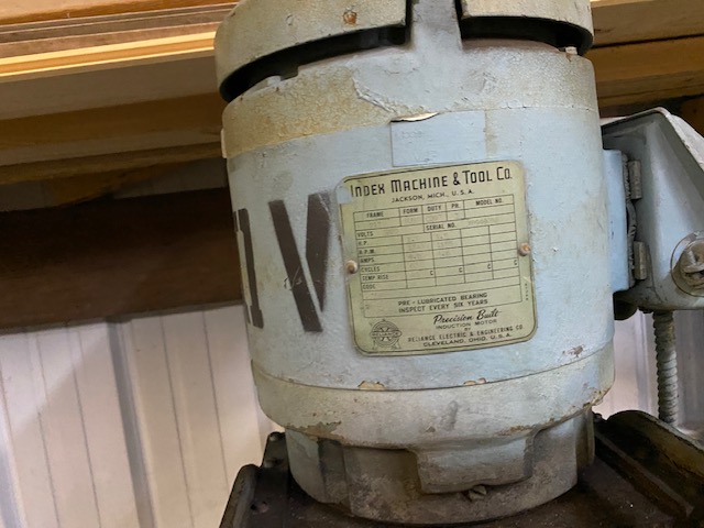
also you better look at the motor name plate and see if they say 240v ... or 480/ 240v .... if they say 480/240v then you have to verify the wires (6) inside the motor electrical box are connected for the right voltage input (230- 240) .... all of those wires should have a TAG on them ( number 1 thru 6), and there should be a wire diagram inside the elect box cover.
|
|
Like them all, but love the "B"s.
|
|
Thad in AR.
Orange Level Access
Joined: 12 Sep 2009
Location: Arkansas
Points: 9733
|
Post Options
Thanks(0)
Quote Reply
Posted: 20 Feb 2023 at 6:23pm |
|
I don’t see a diagram in the motor cover.
The motor tag does say 220 Volt.
The big switch on the left of the columns says FWD off reverse
The one on front that all those wires goes to says 1 off 2
Edited by Thad in AR. - 20 Feb 2023 at 6:33pm
|
|
steve(ill)
Orange Level Access
Joined: 11 Sep 2009
Location: illinois
Points: 90892
|
Post Options
Thanks(0)
Quote Reply
Posted: 20 Feb 2023 at 6:39pm |
The one on front that all those wires goes to says 1 off 2
YEP !!!! i think your on the right track.. I guess it would be normal for a 2 speed motor to only have one voltage.. No need to make to TOO complicated.
Note that in the AB boxes, my wires between the boxes are Red- Green- Brown on the left and Red- Brown - Green on the right... thats how you get the REVERSE.. change two wires.
I still wonder WHY the Table motor wires (?) were cut ?? If they are in fact that.
EDIT..... OK, you thing the 3 small wires are another INPUT and not an OUTPUT to the table ? ..... that would not be normal to have TWO POWER cables into the same 4x4 box.
Edited by steve(ill) - 20 Feb 2023 at 6:44pm
|
|
Like them all, but love the "B"s.
|
|
Thad in AR.
Orange Level Access
Joined: 12 Sep 2009
Location: Arkansas
Points: 9733
|
Post Options
Thanks(0)
Quote Reply
Posted: 20 Feb 2023 at 6:56pm |
|
Steve I haven’t seen any place for them to go.
I’ll try to move it out and get a better look as to where they go.
It’s just a 3 wire.
It has a flexible light on the right side. Could it be 120 volt for that? It’s a factory light I believe???
|
|
steve(ill)
Orange Level Access
Joined: 11 Sep 2009
Location: illinois
Points: 90892
|
Post Options
Thanks(0)
Quote Reply
Posted: 20 Feb 2023 at 7:11pm |
YES, that could be... It is ILLEGAL to run a 3 phase 240 and a single phase 120 in the same 4x4 power box.... But 100 years ago, i would guess OSHA didnt see it ! 
I guess that brings up another question.. If there is 120v single phase power for a LIGHT... did they also use that elsewhere ? ........ Those two AB boxes have a coil on the bottom that the FWD-REV switch sends power to enengize.( the black wires) ... I assumed that was 240 v single phase from 2 of the 3 three phase wires........ its POSSIBLE they used the 120v light bulb wire to also send power to the F-R switch to send power to the coils..... Need to look CLOSE at where the 3 cut wires run.. ( just the light, or other also).
Edited by steve(ill) - 20 Feb 2023 at 7:21pm
|
|
Like them all, but love the "B"s.
|
|
Thad in AR.
Orange Level Access
Joined: 12 Sep 2009
Location: Arkansas
Points: 9733
|
Post Options
Thanks(0)
Quote Reply
Posted: 20 Feb 2023 at 7:36pm |
") steve(ill) wrote: steve(ill) wrote:
YES, that could be... It is ILLEGAL to run a 3 phase 240 and a single phase 120 in the same 4x4 power box.... But 100 years ago, i would guess OSHA didnt see it !
I guess that brings up another question.. If there is 120v single phase power for a LIGHT... did they also use that elsewhere ? ........ Those two AB boxes have a coil on the bottom that the FWD-REV switch sends power to enengize.( the black wires) ... I assumed that was 240 v single phase from 2 of the 3 three phase wires........ its POSSIBLE they used the 120v light bulb wire to also send power to the F-R switch to send power to the coils..... Need to look CLOSE at where the 3 cut wires run.. ( just the light, or other also).
|
Will do. Next time I get a minute I’ll trace all the incoming wires.
|
|
Les Kerf
Orange Level
Joined: 08 May 2020
Location: Idaho
Points: 1640
|
Post Options
Thanks(0)
Quote Reply
Posted: 21 Feb 2023 at 12:29pm |
I helped a friend with a chinese Grizzly woodworking milling/drilling machine that his brother bought really cheap at an auction; someone had just cut the wires to remove it from the auction site. Took me the better part of a day to ohm out everything and make a schematic from scratch. Bleah. 
|
|
DaveKamp
Orange Level Access
Joined: 12 Apr 2010
Location: LeClaire, Ia
Points: 6126
|
Post Options
Thanks(1)
Quote Reply
Posted: 21 Feb 2023 at 9:09pm |
steve(ill) wrote:
It is ILLEGAL to run a 3 phase 240 and a single phase 120 in the same 4x4 power box.... |
NOT necessarily. It is bad practice to bring in TWO separately-derived power supply services into the same machine, through the same box, except for circumstance where all power sources are disengaged by a ganged multivoltage switch...
but it is rare for that to happen in MOST tool environments. The exceptions are usually when the machine has a VERY HIGH voltage input (say... 1200v) for running really large drive motors, but has 120v CNC controls and work lighting. Basically, if there's a 3-phase 480 input, and a 120v single phase, they'd put a dry transformer across two of the 480 legs to derive that control power from downstream of the 480v safety switch.
The other thing that is generally considered bad practice, is to have a neutral wire on a 3-phase machine... i.e. a 480/277Y feeding into a machine, where the Y centerpoint and one leg is providing 277 single-phase to something, while the 480V 3-phase powers a motor. It's considered bad practice (because a neutral means there's zero-sequence current (unbalanced 3-phase load) which, if marginal, makes the machine carry the remainder through it's ground wiring... so having a Y-centerpoint (that's 'centrepoint' for our brethren north of the Poutine Curtain) generally doesn't happen in an industrial environment.
The location of the high/low speed Dahlinder switch MIGHT be located INSIDE the mill's column... with the speed selector shaft protruding to a control handle on the outside of the column. On my Bridgeport, I tucked the VFD, and a control transformer, inside the BRJ column, and mounted the power, lighting, and speed/direction control pendant feedthrough in a box on the side... it's so nice to have it out of the mayhem...
|
|
Ten Amendments, Ten Commandments, and one Golden Rule solve most every problem. Citrus hand-cleaner with Pumice does the rest.
|
|
Thad in AR.
Orange Level Access
Joined: 12 Sep 2009
Location: Arkansas
Points: 9733
|
Post Options
Thanks(0)
Quote Reply
Posted: 22 Feb 2023 at 3:32am |
|
Last night I went to visit my mom tonight I work at the cemetery hopefully tomorrow night o can get out there and trace wires.
I’ve been looking at lots of pics and video of these machines. Most do not have this light.
I wonder if it’s an add on?
|
|