| Author |
 Topic Search Topic Search  Topic Options Topic Options
|
Les Kerf 
Orange Level

Joined: 08 May 2020
Location: Idaho
Points: 1305
|
 Post Options Post Options
") Thanks(0) Thanks(0)
 Quote Quote  Reply Reply
 Topic: C-Cadet Zero Turn Dies as soon as Park Brake is Re Topic: C-Cadet Zero Turn Dies as soon as Park Brake is Re
Posted: 30 Mar 2025 at 5:03pm |
 DaveKamp wrote: DaveKamp wrote:
...the manufacturer added a shorting leaf to the harness side of the connector that, IF the switch is removed (which would result in an open circuit, thus defeated switch), there's a 'safety leaf' that shorts the wires, causing it to then always kill... |
This makes sense. Of course, they neglected to include this in the schematic 
|
 |
|
Sponsored Links
|
|
|
jaybmiller
Orange Level Access
Joined: 12 Sep 2009
Location: Greensville,Ont
Points: 24704
|
Post Options
Thanks(0)
Quote Reply
Posted: 30 Mar 2025 at 1:23pm |
sure... NOW you suggest a plastic fork NOW that they've been BANNED in Canada,eh !!! The wooden wonders come wrapped in plastic though........ Sigh, the seat reminds me of the ones in the old twin Beech on floats ,dbl sigh, that was 1/2 century ago.....
|
|
3 D-14s,A-C forklift, B-112
Kubota BX23S lil' TOOT( The Other Orange Tractor)
Never burn your bridges, unless you can walk on water
|
|
DaveKamp
Orange Level Access
Joined: 12 Apr 2010
Location: LeClaire, Ia
Points: 6077
|
Post Options
Thanks(0)
Quote Reply
Posted: 30 Mar 2025 at 10:05am |
My favorite, Jay, is the tooth of a plastic fork! Jamb it in, break it off, and it's good! ;-)
The seat on my Bob-Cat 60 was suffering the nasty weathered cracked-up vinyl syndrome... y'know, the type that if the missus sits on it, the sharp curled up edges bite into her legs, and the foam (although in the sun) has plenty of moisture in it and soaks her behind.
Well... I solved that. I made a new seat frame consisting of right and left side rails, and made up a really strong canvas hammock that stretched between the rails on the bottom, and another between rails of the top. No foam, just flex and stretch... when it rains, the canvas gets wet, but I waxed it lightly, so most beads up and runs off, and what DOES soak in, dries out immediately.
|
|
Ten Amendments, Ten Commandments, and one Golden Rule solve most every problem. Citrus hand-cleaner with Pumice does the rest.
|
|
jaybmiller
Orange Level Access
Joined: 12 Sep 2009
Location: Greensville,Ont
Points: 24704
|
Post Options
Thanks(0)
Quote Reply
Posted: 30 Mar 2025 at 9:57am |
gee Dave, one day your head will explode from all the neat info you know. That will be a very sorry day !!! My thought is the 'legs' of the 10K open up the 2 switches that short mag to ground. Could use 100K, 1M, 4K7....toothpicks in connector ..same effect
|
|
3 D-14s,A-C forklift, B-112
Kubota BX23S lil' TOOT( The Other Orange Tractor)
Never burn your bridges, unless you can walk on water
|
|
DaveKamp
Orange Level Access
Joined: 12 Apr 2010
Location: LeClaire, Ia
Points: 6077
|
Post Options
Thanks(0)
Quote Reply
Posted: 30 Mar 2025 at 9:53am |
As I said before- this is a relay logic circuit. If you added a
resistor, it wasn't the resistor that had any effect, it cannot. Resistors are not 'magic bullets'.
So I second Steve and Jay - I would bet that
you disconnected the switch right AT the switch, leaving the connector
intact.
Steve's blue note above is correct- on MANY safety switches on these machines, the manufacturer added a shorting leaf to the harness side of the connector that, IF the switch is removed (which would result in an open circuit, thus defeated switch), there's a 'safety leaf' that shorts the wires, causing it to then always kill. This is to prevent widespread disconnection of the seat safety switch, as that was found to be extremely common when the inclusion of these devices (and the result of their malfunction) appeared in the mid '80s. It was, in effect, a safety-within-a-safety, which in theory, made sense, but in practice, made matters worse.
This all started, by the way, as a result of the Consumer Product Safety Act of 1972, and rather than doing it through government, they contracted a non-government organization called "Consumer Union" (now a magazine called Consumer Reports) to write it all into rules and regulation.
This was authoritized through 15 USC 2051, and as a result of 15 US Code 2068, grants regulatory authority (by virtue of the Consumer Product Safety Commission) to a private publications magazine.
More references:
US Code Title 16 Chapter II Subchapter B part
US Code 16 CFR 1205 ANSI B71-1-1972
2051 Congressional Findings (determining that the public can't think for themselves) 2052 Definitions 2056 Consumer Product Safety Standards (para (c) is where some dirt is hidden...)
2058 Procedure for consumer product safety code (writing rules) 2063 Certification and Labeling 2063 Prohibited acts (offering it for sale without meeting standards, and enforcement of recalls
2068 Authority (placing it in the control of an NGO)
The truth is in the logic of the wiring diagram. The insanity, is the path by which it came to us.
Edited by DaveKamp - 30 Mar 2025 at 10:01am
|
|
Ten Amendments, Ten Commandments, and one Golden Rule solve most every problem. Citrus hand-cleaner with Pumice does the rest.
|
|
steve(ill)
Orange Level Access
Joined: 11 Sep 2009
Location: illinois
Points: 87947
|
Post Options
Thanks(0)
Quote Reply
Posted: 30 Mar 2025 at 9:11am |
|
I think JAY IS RIGHT.... when you pull the PLUG off, it SHORTS OUT the two wires internal.... You dont need a resistor, you just need to cut one wire to OPEN the circuit....Removing the plug is the same as Jumpering the two wires together.. BOTH are a SHORT.
Edited by steve(ill) - 30 Mar 2025 at 9:14am
|
|
Like them all, but love the "B"s.
|
|
Gateman
Bronze Level

Joined: 28 Mar 2025
Location: Texas
Points: 17
|
Post Options
Thanks(0)
Quote Reply
Posted: 30 Mar 2025 at 8:54am |
|
It dies if you release the parking break. That’s the reason for putting in the resistor to mimic the seat switch when you’re sitting on it.
|
|
Gateman
Bronze Level
Joined: 28 Mar 2025
Location: Texas
Points: 17
|
Post Options
Thanks(0)
Quote Reply
Posted: 30 Mar 2025 at 8:47am |
|
That’s what the resistor does it mimics the switch at half way pressed.
I couldn’t release the park break without it dying
I unplug the seat switch and twisted the wires together and it’ll start but still dies when you release the parking break.
So I put the resistor in between the wires and now it runs fine. Mows just fine and everything still works like it’s supposed to, it’ll die if you try to drive it with the parking break on so you have to release the break first.
It’s a really simple fix but everyone acts like it’s an impossible solution.
The resistor is from a shaft drive garage door opener, I’ve install hundreds of them over the past 20 years.
Liftmaster puts them in from the factory on some models, it goes in where the cable tensioner plugs in so you can bypass it if you need to.
Same theory here, it gives the right signal so the mower thinks you’re sitting on the seat.
Just be careful because it won’t shutdown if you get off.
|
|
Les Kerf
Orange Level
Joined: 08 May 2020
Location: Idaho
Points: 1305
|
Post Options
Thanks(0)
Quote Reply
Posted: 30 Mar 2025 at 8:16am |
DaveKamp wrote:
... but if the diagram Jay posted is correct, there is nothing in this system that does that... |
I studied this schematic back when it was first posted and came to the same conclusion
|
|
steve(ill)
Orange Level Access
Joined: 11 Sep 2009
Location: illinois
Points: 87947
|
Post Options
Thanks(0)
Quote Reply
Posted: 29 Mar 2025 at 9:39pm |
I dont think were talking ONLY about Bucks mower... "IN GENERAL" ...... I had a small 10 HP Columbia mower that i was removing the deck and all safety switches to basically make a small travel vehicle out of it.. When i got to the SEAT SWITCH it was 2 wires.. Remove the switch and it would not start... Jumper the two wires together and it would not start.. Reinstall the switch and install a bracket to hold it CLOSED all the time, and it starts... AND this is a 2 wire switch................... Never looked deeper into WHY..
just found this on SEARCH.... Might be that when you pull the plug off the switch, THE PLUG shorts out the wires.... If you install a jumper you still short out the wire... POSSIBLY there is no way to get an OPEN CIRCUIT except to CUT THE WIRE ??... apparently the switch is NORMALLY CLOSED and when you set on the seat the switch OPENS... but if you unplug it, the PLUG CLOSES..
BFH is talking about an internal shunt located inside the connector. Look between the two terminals of the plug, you will see a tiny plunger that shorts out the wires when you unplug the switch so that you can't bypass it by simply disconnecting the switch. Just get a zip tie and strap the connector to the switch tightly enough to make it work.
Edited by steve(ill) - 29 Mar 2025 at 10:07pm
|
|
Like them all, but love the "B"s.
|
|
DaveKamp
Orange Level Access
Joined: 12 Apr 2010
Location: LeClaire, Ia
Points: 6077
|
Post Options
Thanks(0)
Quote Reply
Posted: 29 Mar 2025 at 9:23pm |
Gateman wrote:
It is true because it’s working on my mower right now lol. That’s why I posted it. |
If it is, there's either one of three explanations:
1) the diagram Jay found, is not for Buck's mower... or 2) your mower isn't the same as Buck's mower or 3) there is something significantly more wrong with your mower, than Buck's.
Based on the diagram, all Buck would need to do to overcome this problem, would be to disconnect the magneto ground wire, at which time, NO safety functions would kill the engine.
Based on the diagram, the switch contacts will short magneto to ground when
A) the seat is unoccupied anytime the park brake is not set OR the PTO is engaged OR either of the hydrostat control levers are NOT in the PARK position.
B) anytime the seat IS occupied, BUT levers are taken out of the PARK position WHILE the brake is set
C) Anytime the brake is set WHILE either or both of the levers are NOT in the park position.
And finally, the PTO is interlocked through BOTH levers' reverse position switches. It's an AND circuit... For steering, EITHER lever can be in a reverse position by itself, but if BOTH are drawn into reverse, the PTO will be disengaged.
Safety circuits on everything, especially riding mowers, are NOT feeding microprocessor circuits, they're discrete loops of mechanical contacts. This is simple safety unreliant upon processors, code, and sensitive circuitry. On systems that have safety circuitry, you will find 'fail safe' design (meaning, a multi-point failure mode cannot occur in such a way as to leave a machine in an unsafe state), and IF there's any sort of processor inclusion, it has supervisory function (for diagnostic purposes, it can tell you what switch is bad), and in some cases, a microprocessor controller will have a relay output whose contacts are in series with the safety loop, so that it can also become a device able to command a safety shutdown... but if the diagram Jay posted is correct, there is nothing in this system that does that.
The problem that plagues Buck's machine, is most likely a wire, connector, or contact that has either failed to an open state, or failed to a shorted state, as there's no other componentry available to fail.
|
|
Ten Amendments, Ten Commandments, and one Golden Rule solve most every problem. Citrus hand-cleaner with Pumice does the rest.
|
|
steve(ill)
Orange Level Access
Joined: 11 Sep 2009
Location: illinois
Points: 87947
|
Post Options
Thanks(0)
Quote Reply
Posted: 29 Mar 2025 at 12:33pm |
there is still only 2 wires.. Seems like it is OPEN or CLOSED -- you remove the switch and either JUMPER the two or leave them disconnected ... only two options.. and NEITHER will allow the tractor to start..... Seems like the SWITCH being removed is the secret.. Sticking spade terminals into the connector does not fool it ... ????
I need to look into that SOMEDAY... just too many other projects right now.. and it works with the Switch clamped CLOSED.
Edited by steve(ill) - 29 Mar 2025 at 12:35pm
|
|
Like them all, but love the "B"s.
|
|
jaybmiller
Orange Level Access
Joined: 12 Sep 2009
Location: Greensville,Ont
Points: 24704
|
Post Options
Thanks(0)
Quote Reply
Posted: 29 Mar 2025 at 11:26am |
It's not actually the 'switch' , it's the connector on the wiring harness that's 'special'. it's designed so if you do remove the seat switch, mag gets grounded.
the 'trick' is to cut off the special connector.....
|
|
3 D-14s,A-C forklift, B-112
Kubota BX23S lil' TOOT( The Other Orange Tractor)
Never burn your bridges, unless you can walk on water
|
|
steve(ill)
Orange Level Access
Joined: 11 Sep 2009
Location: illinois
Points: 87947
|
Post Options
Thanks(0)
Quote Reply
Posted: 29 Mar 2025 at 8:54am |
|
|
|
Like them all, but love the "B"s.
|
|
steve(ill)
Orange Level Access
Joined: 11 Sep 2009
Location: illinois
Points: 87947
|
Post Options
Thanks(0)
Quote Reply
Posted: 29 Mar 2025 at 8:37am |
i dont know about the resistor... but there is something SPECIAL about the seat switch on SOME TRACTORS... It is NOT and ON- OFF , no matter what the PRINT shows... Take the switch out and the tractor will not start.. short the two wires together and the tractor will not start....
I had to compress the switch and clamp it closed to get our small tractor to work.. Could no "bypass" the switch .. ??????
the post BELOW is from page 1 of this discussion several months ago-- about the SWITCH.
Edited by steve(ill) - 29 Mar 2025 at 8:55am
|
|
Like them all, but love the "B"s.
|
|
jaybmiller
Orange Level Access
Joined: 12 Sep 2009
Location: Greensville,Ont
Points: 24704
|
Post Options
Thanks(0)
Quote Reply
Posted: 29 Mar 2025 at 7:52am |
so cut the resistor out and report back what happens. An 'empirical' test !
|
|
3 D-14s,A-C forklift, B-112
Kubota BX23S lil' TOOT( The Other Orange Tractor)
Never burn your bridges, unless you can walk on water
|
|
Gateman
Bronze Level
Joined: 28 Mar 2025
Location: Texas
Points: 17
|
Post Options
Thanks(0)
Quote Reply
Posted: 28 Mar 2025 at 9:45pm |
|
It is true because it’s working on my mower right now lol. That’s why I posted it.
|
|
DaveKamp
Orange Level Access
Joined: 12 Apr 2010
Location: LeClaire, Ia
Points: 6077
|
Post Options
Thanks(0)
Quote Reply
Posted: 28 Mar 2025 at 9:06pm |
|
That isn't true. It's a logic signal, not an analog signal. The seat presence switch was not properly actuating, either because the switch's overcenter mechanism or contacts were failing, or because the seat structure had degraded and no longer properly activating the switch.
|
|
Ten Amendments, Ten Commandments, and one Golden Rule solve most every problem. Citrus hand-cleaner with Pumice does the rest.
|
|
Gateman
Bronze Level
Joined: 28 Mar 2025
Location: Texas
Points: 17
|
Post Options
Thanks(1)
Quote Reply
Posted: 28 Mar 2025 at 4:03pm |
The way to bypass the seat switch on a two wire switch is to put a 10k resistor between the two wires and it won’t die when you disengage the parking brake. Everything works as it should. 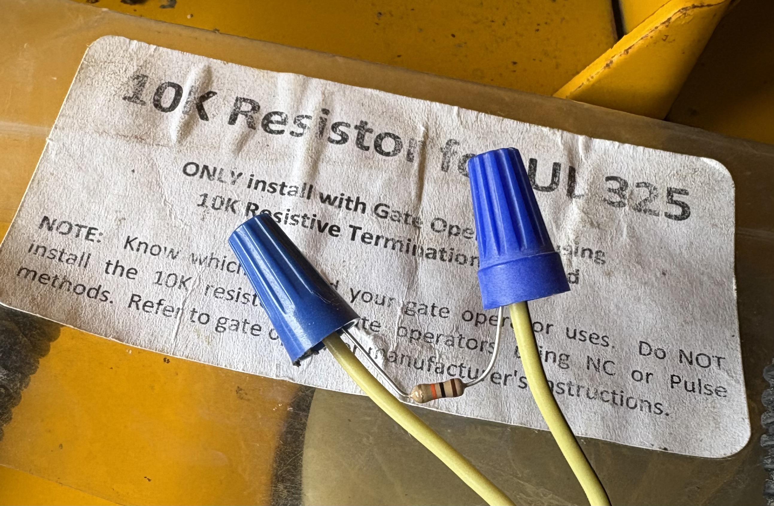
Edited by Gateman - 28 Mar 2025 at 4:04pm
|
|
DiyDave
Orange Level Access

Joined: 11 Sep 2009
Location: Gambrills, MD
Points: 54163
|
Post Options
Thanks(0)
Quote Reply
Posted: 17 May 2024 at 7:02pm |
BuckSkin wrote:
Les Kerf wrote:
It is interesting that it shows two Neutral switches, are there really two of them?
|
Yes; two Neutral Switches, one each side where the "arms" rest when not in action.
On this machine, if either arm is not against it's Neutral Switch, in the "at rest" position, it will not start; but then, once started, they can be anywhere and it will run; however, once it is running and the Park Brake is engaged, if you move either arm from it's at rest position, against the Neutral Switch, the engine will die; you must first dis-engage the Park Brake and then move the arms.
I guess that is to keep you from running around with the brake engaged.
It looks to me like it would be less wear and tear on the engine and starter/flywheel if, instead of any wrong move killing the engine, a cattle prod were incorporated within the seat and the operator get a bit of wake-me-up juice whenever a wrong maneuver were attempted; the lesson would be long remembered and the operator would be sure to follow proper procedure in the future. |
That would make a good video... 
|
|
Source: Babylon Bee. Sponsored by BRAWNDO, its got what you need!
|
|
BuckSkin
Orange Level
Joined: 12 Sep 2019
Location: Poor Farm
Points: 924
|
Post Options
Thanks(0)
Quote Reply
Posted: 17 May 2024 at 5:31pm |
Les Kerf wrote:
It is interesting that it shows two Neutral switches, are there really two of them?
|
Yes; two Neutral Switches, one each side where the "arms" rest when not in action.
On this machine, if either arm is not against it's Neutral Switch, in the "at rest" position, it will not start; but then, once started, they can be anywhere and it will run; however, once it is running and the Park Brake is engaged, if you move either arm from it's at rest position, against the Neutral Switch, the engine will die; you must first dis-engage the Park Brake and then move the arms.
I guess that is to keep you from running around with the brake engaged.
It looks to me like it would be less wear and tear on the engine and starter/flywheel if, instead of any wrong move killing the engine, a cattle prod were incorporated within the seat and the operator get a bit of wake-me-up juice whenever a wrong maneuver were attempted; the lesson would be long remembered and the operator would be sure to follow proper procedure in the future.
|
|
jaybmiller
Orange Level Access
Joined: 12 Sep 2009
Location: Greensville,Ont
Points: 24704
|
Post Options
Thanks(0)
Quote Reply
Posted: 17 May 2024 at 3:17pm |
re: looking at the engine plug, on the engine side is two connected
wires, "Afterfire Sol." and "Charging"; they become a Red wire that
takes an unbroken path to the "L" terminal of the Key Switch; does this
"L" get connected to "B" when the Key is On/Run ? Kohler is clever, the 'charging' module is tied to the 'afterfire solenoid' ON the engine. If you spun the engine,say with recoil starter', engine runs without need of a battery. You need to understand that if a manufacturer can make a 'generic' device (engine in this case )it can be easily used in several devices NOT specific to just one mower seriers of one brand.
As for the grounds, often it's how the wiring harness is made and installed.
Yes, RED, is the alternator/rectifier/regulator output. it goes to 'L' and powers everything. When key is on, it's also on 'B',goes through 20A fuse to recharge the battery. You can pull the 20A fuse and the unit will still run.
Internal connections of the ignition switch are usually shown in a chart and while most Indak switches look the same, Internally they can be quite different so you MUST eplace with one specific to your machine.
The seat switch is just 2 wire, simple SPST switch, NO 'magic' that I can see.
Edited by jaybmiller - 17 May 2024 at 3:20pm
|
|
3 D-14s,A-C forklift, B-112
Kubota BX23S lil' TOOT( The Other Orange Tractor)
Never burn your bridges, unless you can walk on water
|
|
Les Kerf
Orange Level
Joined: 08 May 2020
Location: Idaho
Points: 1305
|
Post Options
Thanks(0)
Quote Reply
Posted: 17 May 2024 at 2:57pm |
BuckSkin wrote:
...does this "L" get connected to "B" when the Key is On/Run ? |
Probably. A proper schematic will show the internal contacts of the ignition switch; it would also actually label the switch so that we would not need to guess. This is really just a wiring diagram rather than a schematic.
BuckSkin wrote:
I am assuming that Red wire is the "Alternator/Charging wire, right ? |
Again, probably. I am assuming so as well.
BuckSkin wrote:
Reason I ask about the connecting of the "L" and "B" is that another Red wire junctions with the main Red wire and is 12-volt power to the PTO-Clutch through the PTO Switch, where it splits into the two Blue wires that pass through the Reverse cut-out switches on their way to being power to the clutch itself. |
Yup, that looks pretty straightforward to me too; the 'ignition' switch needs to be able to disconnect the "L" and "B" terminals so as to not discharge the battery when the engine isn't running but needs to connect them to start the engine and charge the battery.
Since it has a magneto ignition, the 'Ignition' switch doesn't need to supply power to a coil. Most of the circuitry is dedicated to killing the magneto. It is interesting that it shows two Neutral switches, are there really two of them?
|
|
Les Kerf
Orange Level
Joined: 08 May 2020
Location: Idaho
Points: 1305
|
Post Options
Thanks(0)
Quote Reply
Posted: 17 May 2024 at 1:28pm |
BuckSkin wrote:
...I bet the "Real" reason for those two secret switches is to force sales of un-needed Seat Switches; people scratch their heads and puzzle while the grass gets taller and the rain keeps coming and they give up and order a new Seat Switch that does nothing to fix their problem but they keep it anyway. |
That is known as "The Brother-in-law Effect"; the guy that designed it has a brother-in-law who sells the little switches |
|
BuckSkin
Orange Level
Joined: 12 Sep 2019
Location: Poor Farm
Points: 924
|
Post Options
Thanks(0)
Quote Reply
Posted: 17 May 2024 at 11:45am |
Les Kerf wrote:
A rather poorly drawn schematic 
|
and I can see no hint nor evidence of the two tiny "secret" switches hidden within the mower side of the Seat Switch plug/connector.
Things are working for me now and I have more pressing matters to attend to; however, if I have to dive into this again, or I get so curious about it that I can't stand it, I intend to cut that plug out of the circuit and thoroughly bench test it to determine just what and when those two tiny switches are doing.
I am convinced that, if that plug were a normal two-wire plug, then it would not/could not ignore any and all attempts at jumper-wiring it.
I bet the "Real" reason for those two secret switches is to force sales of un-needed Seat Switches; people scratch their heads and puzzle while the grass gets taller and the rain keeps coming and they give up and order a new Seat Switch that does nothing to fix their problem but they keep it anyway.
|
|
BuckSkin
Orange Level
Joined: 12 Sep 2019
Location: Poor Farm
Points: 924
|
Post Options
Thanks(0)
Quote Reply
Posted: 17 May 2024 at 11:33am |
jaybmiller wrote:

|
Thanks for posting the diagram; that appears to be the exact same one I have been looking at.
Ever since I started studying that diagram, I have been puzzled about those two Grounds at extreme right of the picture.
From the actual PTO Clutch, at bottom right, the Green wire is an unbroken path to Engine Ground.
Then, at just above right-center, is a black dot which I take to be a splice/junction, with another wire going through the Kohler Engine Plug to Ground again ----- why both ?
Also, looking at the engine plug, on the engine side is two connected wires, "Afterfire Sol." and "Charging"; they become a Red wire that takes an unbroken path to the "L" terminal of the Key Switch; does this "L" get connected to "B" when the Key is On/Run ?
I am assuming that Red wire is the "Alternator/Charging wire, right ?
Reason I ask about the connecting of the "L" and "B" is that another Red wire junctions with the main Red wire and is 12-volt power to the PTO-Clutch through the PTO Switch, where it splits into the two Blue wires that pass through the Reverse cut-out switches on their way to being power to the clutch itself.
By the way, the best thing I have done to this mower is disabling those Reverse Cutout Switches so that I can now mow when backing up; it makes all the difference in the world in tall/tough grass and whether it gets cut or not.
|
|
Les Kerf
Orange Level
Joined: 08 May 2020
Location: Idaho
Points: 1305
|
Post Options
Thanks(0)
Quote Reply
Posted: 17 May 2024 at 9:31am |
A rather poorly drawn schematic
|
|
jaybmiller
Orange Level Access
Joined: 12 Sep 2009
Location: Greensville,Ont
Points: 24704
|
Post Options
Thanks(0)
Quote Reply
Posted: 17 May 2024 at 6:26am |
OK, had to kill time while coffee was being made...... oopsy... upper right switch is the 'neutral switch'..... my cut and paste was a tad shaky ( only 1st cup of joe.....)
jay
|
|
3 D-14s,A-C forklift, B-112
Kubota BX23S lil' TOOT( The Other Orange Tractor)
Never burn your bridges, unless you can walk on water
|
|
jaybmiller
Orange Level Access
Joined: 12 Sep 2009
Location: Greensville,Ont
Points: 24704
|
Post Options
Thanks(0)
Quote Reply
Posted: 17 May 2024 at 6:23am |
|
|
|
3 D-14s,A-C forklift, B-112
Kubota BX23S lil' TOOT( The Other Orange Tractor)
Never burn your bridges, unless you can walk on water
|
|
jaybmiller
Orange Level Access
Joined: 12 Sep 2009
Location: Greensville,Ont
Points: 24704
|
Post Options
Thanks(0)
Quote Reply
Posted: 17 May 2024 at 6:13am |
OK, took me 75 seconds to find to find the wiring....
..maybe someone can convert to an 'image' to repost it ?
Jay
|
|
3 D-14s,A-C forklift, B-112
Kubota BX23S lil' TOOT( The Other Orange Tractor)
Never burn your bridges, unless you can walk on water
|
|


