| Author |
 Topic Search Topic Search  Topic Options Topic Options
|
banjojelly 
Bronze Level

Joined: 26 Nov 2024
Location: S. Illinois
Points: 15
|
 Post Options Post Options
") Thanks(0) Thanks(0)
 Quote Quote  Reply Reply
 Topic: Suggestions on Adding a Hydraulic Valve on a WD Topic: Suggestions on Adding a Hydraulic Valve on a WD
Posted: 26 Nov 2024 at 11:47am |
Hello. I usually frequent a different tractor related forum, but most of the tractor guys have left and it is mostly lawn and garden stuff now.
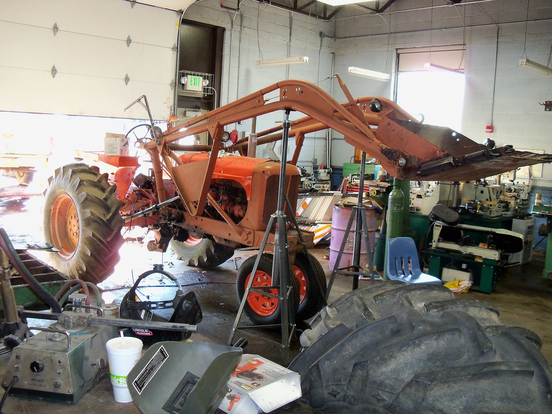
I have a WD with a loader that I have been using for small jobs around the house for about 8 years now. The large loader tractor and Kubota skid steer that we use on the farm are only about a mile from my house, so I can grab them if I need them, but having the WD around for moving stuff is pretty handy.
My issue has become that my hydraulic lever has gotten to the point where it will no longer stay in position. I have tried pretty much everything I can do to make it stay put. It not just a creep. It either wants to be full pressure up, or drop. I am not going to waste a bunch of money rebuilding the selector assembly. The hydraulics are strong. I would like to just plumb in a spool valve and run my loader from that. I am not that familiar with the AC high pressure/ low volume system and it only needs to be a one way valve on top of that. My loader is a trip bucket.
If anyone has ever done this before and could steer me in the right direction to do it as efficiently and cheap as possible, it would be much appreciated.
Edited by banjojelly - 26 Nov 2024 at 12:27pm
|
 |
|
Sponsored Links
|
|
|
Ray54
Orange Level Access

Joined: 22 Nov 2009
Location: Paso Robles, Ca
Points: 4673
|
Post Options
Thanks(0)
Quote Reply
Posted: 26 Nov 2024 at 1:27pm |
A simple no cost way to check out if the problem is the packing on the piston in the rams. Lift the boom up and let it drop a number of times. Put your hand on the ram, if it is much warmer than surrounding metal it is, it is the ram not your control valve. If the seal is bad on the piston of the ram oil leaks past and the friction creates heat.
I also use to worry that the control valve was leaking in situations like you have. Most times it is internal seals in the ram, and no oil is leaking to the outside.
|
|
banjojelly
Bronze Level
Joined: 26 Nov 2024
Location: S. Illinois
Points: 15
|
Post Options
Thanks(0)
Quote Reply
Posted: 26 Nov 2024 at 1:38pm |
If you are referring to the lift cylinders on my loader as being the rams, then I know they are not the problem. I honed and re-cupped them and replaced the wiper seals when I got the tractor running. They will hold position if the engine is off.
If you are referring to something else as being the rams, then you will have to elaborate for me.
|
|
DSeries4
Orange Level

Joined: 12 Sep 2009
Location: Ontario, Canada
Points: 7445
|
Post Options
Thanks(0)
Quote Reply
Posted: 26 Nov 2024 at 2:30pm |
|
The friction block on the lift lever is worn so the handle does not stay in position. You can get a new friction block from Steiners or DJS. Pretty cheap.
|
|
'49 G, '54 WD45, '55 CA, '56 WD45D, '57 WD45, '58 D14, '59 D14, '60 D14, '61 D15D, '66 D15II, '66 D21II, '67 D17IV, '67 D17IVD, '67 190XTD, '73 620, '76 185, '77 175, '84 8030, '85 6080
|
|
banjojelly
Bronze Level
Joined: 26 Nov 2024
Location: S. Illinois
Points: 15
|
Post Options
Thanks(0)
Quote Reply
Posted: 26 Nov 2024 at 2:39pm |
 DSeries4 wrote: DSeries4 wrote:
The friction block on the lift lever is worn so the handle does not stay in position. You can get a new friction block from Steiners or DJS. Pretty cheap.
|
Sorry, I guess I didn't explain it very well. Even if I hold the lever in one position, it still will not stop moving. I even tried clamping the lever in place to the quadrant with vice grips but it still would either be dropping or raising. I feel like it is something further into the valving other than just the lever itself.
|
|
DrAllis
Orange Level Access
Joined: 12 Sep 2009
Points: 21408
|
Post Options
Thanks(0)
Quote Reply
Posted: 26 Nov 2024 at 2:46pm |
|
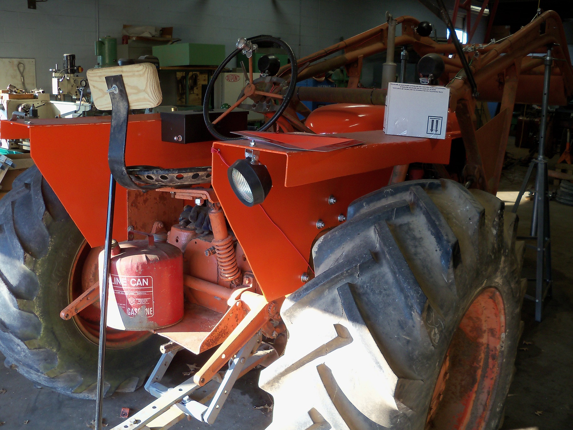
Tractors hydraulic pump isn't set for "HOLD" position work. Read the decal on the side of the battery box.
|
|
banjojelly
Bronze Level
Joined: 26 Nov 2024
Location: S. Illinois
Points: 15
|
Post Options
Thanks(0)
Quote Reply
Posted: 26 Nov 2024 at 2:52pm |
DrAllis wrote:
Tractors hydraulic pump isn't set for "HOLD" position work. Read the decal on the side of the battery box. |
I dont have a battery box, let alone a decal. This is a working tractor, not a barn queen.
I guess I need to rephrase my initial question. I don't want to keep messing with the lever set up anymore.
Can anyone tell me how to add a hydraulic spool valve to a WD?
Thank you.
|
|
HudCo
Orange Level

Joined: 29 Jan 2013
Location: Plymouth Utah
Points: 3794
|
Post Options
Thanks(0)
Quote Reply
Posted: 26 Nov 2024 at 7:30pm |
|
you still have get the pump fuctioning correctly to run extra valves and remotes i have an extra valve and remotes on my wd i still use the lever on the quadrant for the lift arms and the one factory remote but i dont run my pump preasure continus if i dont have to . i have a permant 5000 psi guage on the top of my pump for a referance , and i seperate the two systems with a diverter valve
|
|
banjojelly
Bronze Level
Joined: 26 Nov 2024
Location: S. Illinois
Points: 15
|
Post Options
Thanks(0)
Quote Reply
Posted: 26 Nov 2024 at 8:10pm |
HudCo wrote:
you still have get the pump fuctioning correctly to run extra valves and remotes i have an extra valve and remotes on my wd i still use the lever on the quadrant for the lift arms and the one factory remote but i dont run my pump preasure continus if i dont have to . i have a permant 5000 psi guage on the top of my pump for a referance , and i seperate the two systems with a diverter valve |
So you dont just leave the pump on and let it dead head against a valve? Is this to prevent heat build up or does the pump not bypass internally at a given pressure?
I am not using the rear lift. I have a counter weight box permanently mounted on the rear anyway. I really on need to be able to run the loader.
|
|
Ted J
Orange Level

Joined: 05 Jul 2010
Location: La Crosse, WI
Points: 18923
|
Post Options
Thanks(0)
Quote Reply
Posted: 26 Nov 2024 at 8:23pm |
Do you have a manual for the tractor? The directions are in there for setting up the pump and the linkage. You need to have the linkage set up for 'Hold'. After you get this set, you'll have NO problems using it.
|
|
"Allis-Express"
19?? WC / 1941 C / 1952 CA / 1956 WD45 / 1957 WD45 / 1958 D-17
|
|
banjojelly
Bronze Level
Joined: 26 Nov 2024
Location: S. Illinois
Points: 15
|
Post Options
Thanks(0)
Quote Reply
Posted: 26 Nov 2024 at 9:30pm |
Ted J wrote:
Do you have a manual for the tractor? The directions are in there for setting up the pump and the linkage. You need to have the linkage set up for 'Hold'. After you get this set, you'll have NO problems using it.
|
Yes I have a manual. In order to make it work correctly, I would have to replace a lot of worn out parts that are not worth replacing. We have 5 WD's on our farm. None of them have hydraulics that will hold anymore. I am sorry if I seem rude, but I am not interested in continuing to fight with the worn out quadrant lever. Even if it was functioning perfectly, it is not a good set up for a loader, especially when you have to use the hand clutch in order to fake live hydraulics.
I am only looking for help on how to put a valve block on it to bypass the lever. My hydraulic pump is strong, it is just the valving and lever that is worn/ broken. If everyone else wants to restore theirs to perfect factory condition, be my guest. But this one was $600 with the loader. I am not wanting to restore it, I am wanting to use it.
|
|
DrAllis
Orange Level Access
Joined: 12 Sep 2009
Points: 21408
|
Post Options
Thanks(0)
Quote Reply
Posted: 26 Nov 2024 at 10:30pm |
|
Any "add-on" valve to raise your loader up/down/hold will be rated for 2400 psi. Your tractors pump, if in great condition, is 3400 psi. So, right off the bat, your lifting power will be drastically reduced. Maybe that doesn't matter. You will still have to use the tractors worn out LIFT/LOWER lever to turn on the pump and to shut it off when hydraulics aren't needed. And, whatever you wind up doing, the hand clutch will still be required.
|
|
jvin248
Silver Level


Joined: 17 Jan 2022
Location: Detroit
Points: 422
|
Post Options
Thanks(0)
Quote Reply
Posted: 26 Nov 2024 at 11:23pm |
.
Ontario tractor YouTube channel added a spool valve so they could run their round baler. That may be what you want.
Link to the battery box decal
That diagram shows which bolts to twist to get the action you want. Search for hydraulic decal if the link is bad.
That's cheaper than a spool valve.
Edited by jvin248 - 26 Nov 2024 at 11:28pm
|
|
banjojelly
Bronze Level
Joined: 26 Nov 2024
Location: S. Illinois
Points: 15
|
Post Options
Thanks(0)
Quote Reply
Posted: 26 Nov 2024 at 11:24pm |
DrAllis wrote:
Any "add-on" valve to raise your loader up/down/hold will be rated for 2400 psi. Your tractors pump, if in great condition, is 3400 psi. So, right off the bat, your lifting power will be drastically reduced. Maybe that doesn't matter. You will still have to use the tractors worn out LIFT/LOWER lever to turn on the pump and to shut it off when hydraulics aren't needed. And, whatever you wind up doing, the hand clutch will still be required. |
Where does the 2400psi rating come from? A quick look at single block valves and I see PSI ratings from 3000 to 3625. I am probably going to try and scavenge one from another machine, but that seems reasonable.
Can the pump not stay on if a valve is being used to control it? I guess I don't understand why the pump would need to be off if a valve is installed. The hydraulic pumps on other tractors run all the time. The power steering pump in your car or truck runs all the time. They just bypass internally. If I can just leave the pump on and let it dead head at the valve, then the quadrant lever is not necessary. The only thing I can see that turning the pump off on the factory system does is allow the fluid to back flow to use gravity down. If I had a valve, I could run the return side back to the pump sump, if I knew where to tie into it at.
I am not claiming to know exactly what I am doing. But I have been farming for 25 years and teaching high school shop for 16. I have training as a machinist, although I did not pursue that career. I do know a little bit about machinery. The AC system is just different than the Farmall and Ford and of course any of the more modern equipment we are using like our Magnum series Case's. Before I tore into it myself, I thought it wise to check with people who have more experience to get information about moving forward. Maybe those people don't agree. Idk. I am not trying to be argumentative, I am genuinely trying to figure out how to make it work. Part of the fun for me is making it work from junk I can scavenge and have laying around. If I just want a set of loader arms to pick something up I would just go grab the skid steer and do it.
And yes, I realize the hand clutch will still be required. But riding the hand clutch and controlling a detent valve seems a whole lot more intuitive than riding a hand clutch forward and backward and the quadrant lever up and down, both at the same time. Its like trying to pat your head and rub your belly while trying not to crash into whatever you are trying to pick up or dump.
Edited by banjojelly - 26 Nov 2024 at 11:28pm
|
|
Les Kerf
Orange Level
Joined: 08 May 2020
Location: Idaho
Points: 1072
|
Post Options
Thanks(0)
Quote Reply
Posted: 26 Nov 2024 at 11:32pm |
banjojelly wrote:
...I am only looking for help on how to put a valve block on it to bypass the lever. My hydraulic pump is strong, it is just the valving and lever that is worn/ broken... |
I have never worked on a WD type hydraulic pump, so I just now spent five minutes perusing my I&J manual. That is one almighty confusing contraption! I certainly have more questions now than answers  And I have done 'some' work with industrial hydraulics, both open and closed center stuff, etc.
I will make this statement: if you cannot explain how that thing works, it is probably best to leave it well enough alone. My late Father-in-law simply attached a 'normal' pump to the belt pulley drive on his WD, it worked fine.
Best wishes on your endeavors 
|
|
banjojelly
Bronze Level
Joined: 26 Nov 2024
Location: S. Illinois
Points: 15
|
Post Options
Thanks(0)
Quote Reply
Posted: 26 Nov 2024 at 11:37pm |
jvin248 wrote:
.
Ontario tractor YouTube channel added a spool valve so they could run their round baler. That may be what you want.
Link to the battery box decal
That diagram shows which bolts to twist to get the action you want. Search for hydraulic decal if the link is bad.
That's cheaper than a spool valve.
|
Thank your for the lead on the video, that was very helpful.
Again, I am not looking for information on how to fix my linkage and valving to make the lever work. I could definitely go that route if I wanted to. But..... I don't want to. I would like to try and put a spool valve on it.
I will not be buying a new one. I will be scavenging one from a parts machine. Finding double or triple valves is no problem, I have several. I will have to do some crawling in our machinery grave yard for a single. But I'm sure I will find one.
|
|
banjojelly
Bronze Level
Joined: 26 Nov 2024
Location: S. Illinois
Points: 15
|
Post Options
Thanks(0)
Quote Reply
Posted: 26 Nov 2024 at 11:45pm |
Les Kerf wrote:
banjojelly wrote:
...I am only looking for help on how to put a valve block on it to bypass the lever. My hydraulic pump is strong, it is just the valving and lever that is worn/ broken... |
I have never worked on a WD type hydraulic pump, so I just now spent five minutes perusing my I&J manual. That is one almighty confusing contraption! I certainly have more questions now than answers And I have done 'some' work with industrial hydraulics, both open and closed center stuff, etc.
I will make this statement: if you cannot explain how that thing works, it is probably best to leave it well enough alone. My late Father-in-law simply attached a 'normal' pump to the belt pulley drive on his WD, it worked fine.
Best wishes on your endeavors |
I agree, it is a strange set up. I will give them credit for trying something different.
I will respectfully disagree with your statement. The best way to figure out how it works is to work with it. Its not brain surgery, its a 600 dollar tractor. I don't need to fully understand the intricacy's of their pump blueprints in order to understand how hydraulic fluid makes a cylinder move. Heck I had to take two classes of fluid dynamics in college! I passed but man those were the worst grades I ever got in college.
What I am gathering through this is that most people must not know how it works so the answer is put back the way it was and leave it alone. haha.
Thank you much for the well wishes.
Edited by banjojelly - 26 Nov 2024 at 11:49pm
|
|
DrAllis
Orange Level Access
Joined: 12 Sep 2009
Points: 21408
|
Post Options
Thanks(0)
Quote Reply
Posted: 27 Nov 2024 at 6:38am |
|
2200-2400 psi has been an industry standard since 1960 for open-center type valves. The relief is built into the valve itself. If you have found something rated higher than that, go for it. The WD hyd pump isn't really designed to run for 8 hrs a day with the LIFT/LOWER lever up all the time, but you can do it Pump service life over time I would expect could be shortened.
|
|
banjojelly
Bronze Level
Joined: 26 Nov 2024
Location: S. Illinois
Points: 15
|
Post Options
Thanks(0)
Quote Reply
Posted: 27 Nov 2024 at 8:15am |
DrAllis wrote:
2200-2400 psi has been an industry standard since 1960 for open-center type valves. The relief is built into the valve itself. If you have found something rated higher than that, go for it. The WD hyd pump isn't really designed to run for 8 hrs a day with the LIFT/LOWER lever up all the time, but you can do it Pump service life over time I would expect could be shortened. |
Thanks. My tractor is used more like a forklift than a tractor at this point. It gets started and I move stuff around with it and then gets parked again. It runs for maybe an hour straight at a time at most.
Is there a port where a return line could be plumbed in order to have a fluid return for lowering the loader? On lots of other older tractors, the hydraulic oil is in the transmission and it is easy to do, but on an AC I am pretty sure the transmission and hydraulic sump are separate. I may be incorrect though.
|
|
Les Kerf
Orange Level
Joined: 08 May 2020
Location: Idaho
Points: 1072
|
Post Options
Thanks(0)
Quote Reply
Posted: 27 Nov 2024 at 8:57am |
banjojelly wrote:
... The best way to figure out how it works is to work with it. Its not brain surgery,..
|
Indeed. Since I am an actual (retired) Bio-Medical Engineer (working with medical equipment that brain surgeons use) my inclination is to first learn how it is supposed to work, then fix it.
banjojelly wrote:
...It either wants to be full pressure up, or drop... |
It sounds to me like you have already figured out how it works; now just position the valve controls to send full pressure up all the time, weld it in place, run the outlet line to your 'new' control valve and from there to the cylinders, and dump the return into the fill hole. Simple.
|
|
steve(ill)
Orange Level Access
Joined: 11 Sep 2009
Location: illinois
Points: 85776
|
Post Options
Thanks(1)
Quote Reply
Posted: 27 Nov 2024 at 9:09am |
|
youi need a valve with an OPEN CENTER... The pump can run continuous and will pump THRU THE VALVE back to the hydraulic case ( you will need a return hose).... You can get a single valve or double if you need two seperate "LIFT" systems ( like a dump bucket)... If all you need is the RAISE cylinders, then a single valve with OPEN CENTER will do the trick.
|
|
Like them all, but love the "B"s.
|
|
steve(ill)
Orange Level Access
Joined: 11 Sep 2009
Location: illinois
Points: 85776
|
Post Options
Thanks(1)
Quote Reply
Posted: 27 Nov 2024 at 9:14am |
|
some external valves will be RAISE / HOLD / FLOAT.... others will be RAISE / HOLD / POWER DOWN ....... if you get the POWER DOWN valve, you will need to route that hose back to sump... If you havae the FLOAT valve, with open center, your OK.
|
|
Like them all, but love the "B"s.
|
|
steve(ill)
Orange Level Access
Joined: 11 Sep 2009
Location: illinois
Points: 85776
|
Post Options
Thanks(1)
Quote Reply
Posted: 27 Nov 2024 at 9:26am |
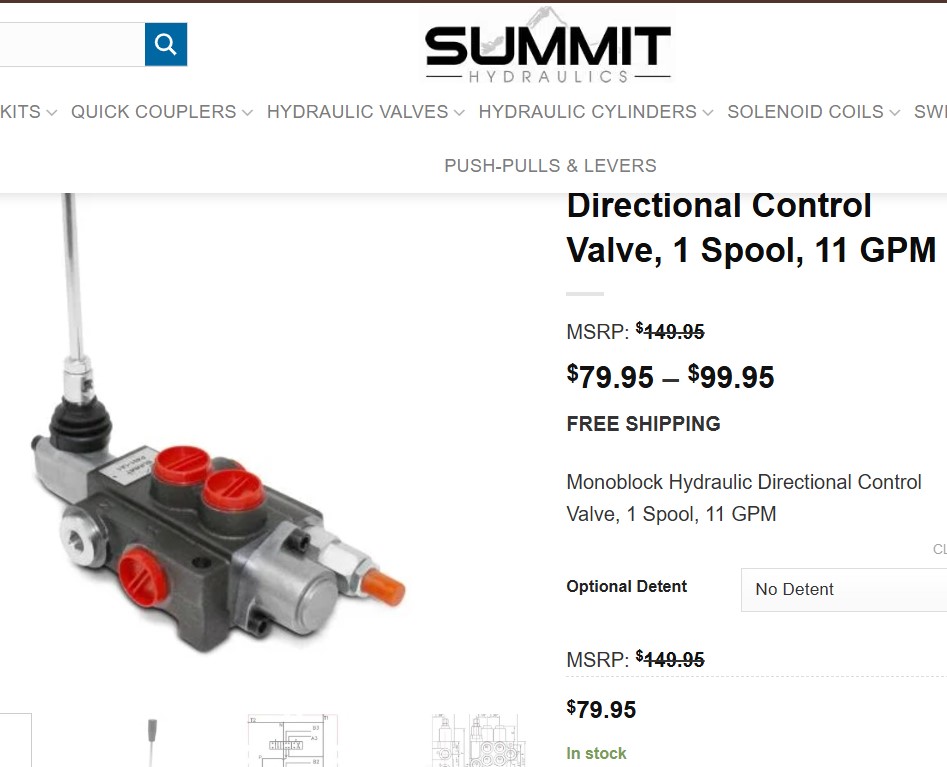
Benefits:- 1 Spool valve with compact design allows for installations in tight areas
- All spools are standard double acting with spring return to neutral position which are ideal for double acting cylinders
- Used for open center systems (Pump to Tank Flow) – closed center option available
- Anti-drop load checks on each spool
- Precision ground and hard chrome-plated spools assure a long life
- High-tensile strength cast iron monoblock construction
- SAE O-Ring ports ensure solid seal and prevent blockages
- Capable of closed center or Power Beyond (conversion plug required)
- Vertical or horizontal handle mount
- Adjustable Relief Valve Range: 1500 to 3625 PSI
- Preset Pressure Relief: 2610 PSI
- Used as
motor or single-acting spool possible (#8 SAE port plug required)
Features:- Max Operating Pressure: P = 3625 PSI, T = 725 PSI, A & B = 4350 PSI
- Flow Rating: 11 GPM (40 l/min)
- A & B Work Ports: #8 SAE O-Ring (3/4”-16) Thread
- Inlet Port: #10 SAE O-Ring (7/8”-14) Thread
- Outlet Port: #10 SAE O-Ring (7/8”-14) Thread
Edited by steve(ill) - 27 Nov 2024 at 9:28am
|
|
Like them all, but love the "B"s.
|
|
banjojelly
Bronze Level
Joined: 26 Nov 2024
Location: S. Illinois
Points: 15
|
Post Options
Thanks(0)
Quote Reply
Posted: 27 Nov 2024 at 9:53am |
Les Kerf wrote:
banjojelly wrote:
... The best way to figure out how it works is to work with it. Its not brain surgery,..
|
Indeed. Since I am an actual (retired) Bio-Medical Engineer (working with medical equipment that brain surgeons use) my inclination is to first learn how it is supposed to work, then fix it.
banjojelly wrote:
...It either wants to be full pressure up, or drop... |
It sounds to me like you have already figured out how it works; now just position the valve controls to send full pressure up all the time, weld it in place, run the outlet line to your 'new' control valve and from there to the cylinders, and dump the return into the fill hole. Simple.
|
Ah. Yes, engineers have a different view than fabricators. Engineers design first, build second. Fabricators tend to design and build as the same process. I would put myself fully in the second category.
As for the second part, can I run the return straight back into the fill hole? I would think the system would have to vent somewhere. I am 100% willing to try it, just like to have a good idea of how it needs to work going forward.
|
|
banjojelly
Bronze Level
Joined: 26 Nov 2024
Location: S. Illinois
Points: 15
|
Post Options
Thanks(0)
Quote Reply
Posted: 27 Nov 2024 at 9:56am |
steve(ill) wrote:
Benefits:- 1 Spool valve with compact design allows for installations in tight areas
- All spools are standard double acting with spring return to neutral position which are ideal for double acting cylinders
- Used for open center systems (Pump to Tank Flow) – closed center option available
- Anti-drop load checks on each spool
- Precision ground and hard chrome-plated spools assure a long life
- High-tensile strength cast iron monoblock construction
- SAE O-Ring ports ensure solid seal and prevent blockages
- Capable of closed center or Power Beyond (conversion plug required)
- Vertical or horizontal handle mount
- Adjustable Relief Valve Range: 1500 to 3625 PSI
- Preset Pressure Relief: 2610 PSI
- Used as
motor or single-acting spool possible (#8 SAE port plug required)
Features:- Max Operating Pressure: P = 3625 PSI, T = 725 PSI, A & B = 4350 PSI
- Flow Rating: 11 GPM (40 l/min)
- A & B Work Ports: #8 SAE O-Ring (3/4”-16) Thread
- Inlet Port: #10 SAE O-Ring (7/8”-14) Thread
- Outlet Port: #10 SAE O-Ring (7/8”-14) Thread
|
Thank you sir. The information from your posts is very much appreciated. I am starting to get a good picture of how I can make this work.
Would you happen to know where the return could be run to on the pump housing or transmission to get it into the sump?
|
|
DrAllis
Orange Level Access
Joined: 12 Sep 2009
Points: 21408
|
Post Options
Thanks(1)
Quote Reply
Posted: 27 Nov 2024 at 10:02am |
|
Remove the drain plug to the hydraulic sump, install a tee, return oil into the side of the tee and still have a drain plug on the bottom.
|
|
Les Kerf
Orange Level
Joined: 08 May 2020
Location: Idaho
Points: 1072
|
Post Options
Thanks(0)
Quote Reply
Posted: 27 Nov 2024 at 10:24am |
banjojelly wrote:
...Ah. Yes, engineers have a different view than fabricators. Engineers design first, build second. Fabricators tend to design and build as the same process. I would put myself fully in the second category. |
Yup. Before I switched careers I worked in sawmill maintenance for 30 years as a saw filer. I have a fair amount of experience from both perspectives
banjojelly wrote:
...As for the second part, can I run the return straight back into the fill hole? ... |
Yes. But Dr Allis' suggestion is better, and Steve has the correct valve configurations.
|
|
banjojelly
Bronze Level
Joined: 26 Nov 2024
Location: S. Illinois
Points: 15
|
Post Options
Thanks(0)
Quote Reply
Posted: 27 Nov 2024 at 10:33am |
DrAllis wrote:
Remove the drain plug to the hydraulic sump, install a tee, return oil into the side of the tee and still have a drain plug on the bottom. |
This is a great idea. Thank you. I was thinking I would need to go in from the top. I was not thinking about the drain plug being an option.
|
|
banjojelly
Bronze Level
Joined: 26 Nov 2024
Location: S. Illinois
Points: 15
|
Post Options
Thanks(0)
Quote Reply
Posted: 27 Nov 2024 at 10:39am |
|
I appreciate all the insight. I am getting a pretty good picture in my mind of how to put a system together. I am thinking I may just build a set of forks for it while I am at it and remove the bucket. I do not have tilt cylinders, but I think I can easily control the fork tilt with a cheap #3500 electric winch. I am usually only picking up car and truck parts with it or moving small logs and trees. Anything too heavy and my steering goes away real fast.
|
|