| Author |
 Topic Search Topic Search  Topic Options Topic Options
|
john 
Silver Level


Joined: 12 Sep 2009
Location: il
Points: 53
|
 Post Options Post Options
") Thanks(0) Thanks(0)
 Quote Quote  Reply Reply
 Topic: From Niehoff to Delco Topic: From Niehoff to Delco
Posted: 19 Dec 2011 at 3:07pm |
|
I have a 7040 that I had since 95 only run like 50 hrs a year .I replaced the alternator it had a Niehoff on it.The new Niehoff only lasted 100 hrs or so paid 700.00 for it I think .Over the years I just charged the bat every few days .I got a Delco to put on it .There are 3 wires on the tractor and places for 4 on the Delco the bat and 3 on the plug . how do I hook this up I know were the bat wire goes that was easy ........... thanks
|
 |
|
Sponsored Links
|
|
|
soybreedingboy77
Bronze Level

Joined: 14 Dec 2011
Location: Illinois
Points: 185
|
Post Options
Thanks(0)
Quote Reply
Posted: 19 Dec 2011 at 8:58pm |
|
The Delco 3 wire plug has a rpm pin in it also. The RPM/Tach blade is the one to the inside/ out of line with the others. The 6080 and some of the 8000 series ran the tach off of the alternator. However, the 7000 and some of the 8000 had a flywheel sensor for RPM.
|
|
Travis(NE)
Silver Level
Joined: 24 Sep 2009
Location: Seward NE
Points: 300
|
Post Options
Thanks(0)
Quote Reply
Posted: 19 Dec 2011 at 9:30pm |
It's been a while since I've worked on one, so hopefully Steve or somebody else will verify...
Pin 1 is the exciter terminal ie turns the alt on - should go to the wire that is switched 12+
Pin 2 is the sensing terminal ie tells the alt battery voltage so it knows how much to charge - should go directly to the battery or wire that is hot all the time
Pin 3 is the tach wire - goes to the tach - the wire that may not show any voltage?
The pin numbers are usually marked on the end housing where the plug goes in on the pins
|
|
MACK
Orange Level

Joined: 17 Nov 2009
Points: 7664
|
Post Options
Thanks(0)
Quote Reply
Posted: 20 Dec 2011 at 6:51am |
Some of the 7040 had both wireings on them.
Only the 8000 series used the flywheel pickup. MACK
|
|
Steve in NJ
Orange Level Access

Joined: 12 Sep 2009
Location: Andover, NJ
Points: 12043
|
Post Options
Thanks(0)
Quote Reply
Posted: 20 Dec 2011 at 6:56am |
What model Alternator are you trying to use? Some Delco units can be direct replacements, some aren't. What was the Neihoff model # that was on the Tractor? I can tell you what Delco unit to use if there's a direct replacement for that particular Neihoff. One other thing, if you only got a year out of the Niehoff, you obviously have a problem on board that Tractor that's causing the problem. I would check into that first, make the necessary repair, and then have a good rebuilding shop look at the Neihoff for you to repair it. Niehoff, Denso's Motorola's etc are not cheap units to purchase. They are usually good reliable units, but like anything else, if there's a problem on board somewhere that would cause them to fail, the replacement unit you're putting on can fail just as fast. You'll be broke if you keep doing that, and the Tractor still will not be performing the way it should.... HTH
|
|
john
Silver Level
Joined: 12 Sep 2009
Location: il
Points: 53
|
Post Options
Thanks(0)
Quote Reply
Posted: 20 Dec 2011 at 8:33am |
|
Niehoff model a1-127 volts 12 amps 100 rel had blk wire ...b+ had bat wire... red wire went to a termanal not marked ......and a gnd pin no wire ......tractor number 70404619 delco only has the markings made in china .....it has a place for the bat wire and 3 prong plug that has no markings on it the plug or in the alt. what kind of problem on board been charging w a bat charger 10 years and never found any thing ? just dont know how to find it it there is a problem on board .the Niehoff had a gnd pin no wire was hooked to it could that be the probmem ? Travis From what you said I think I will need to find a wire from the key switch for pin 1 ...If I test the wire for pine 2 it should be hot all the time ...pin 3 is tach .....the tractor has a wire for the bat the biger one and two smaller wires blk and red one chould be hot all the time and go to pin 2 the other is the tach to pin 3 and I need to run a wire from a keyswitch wire for pin one ..does this sound like a place to start ??? thanks for all your help
Edited by john - 20 Dec 2011 at 8:44am
|
|
john
Silver Level
Joined: 12 Sep 2009
Location: il
Points: 53
|
Post Options
Thanks(0)
Quote Reply
Posted: 20 Dec 2011 at 2:42pm |
I got the pin info from the seller of the what I think is a delco here is a pict 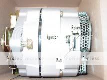
|
|
Travis(NE)
Silver Level
Joined: 24 Sep 2009
Location: Seward NE
Points: 300
|
Post Options
Thanks(0)
Quote Reply
Posted: 20 Dec 2011 at 11:56pm |
Does your tach or if it has a charging warning light on the dash currently work with the neihoff?
That picture is wrong. The markings on the pins need to be moved counter-clockwise one pin. Here is a pic I got from an I&T manual. 
I know pin 1 is exciter/ignition and pin 2 is sensing/battery, but this picture doesn't show pin 3.
Pin 1 only needs low voltage to excite/turn on the alternator and is often connected to a light on the dash. If the bulb is burnt out or does not come on with the key on engine not running there will be no voltage at the alternator.
Pin 2 can also be connected directly to the output terminal on the back of the alternator, but if there is any wiring issues the alt may not charge the batteries as it is sensing the voltage right at the alt and not the batteries.
I can't find my manual with a good wiring diagram at the moment. I hope this helps and doesn't confuse you.
|
|
Coke-in-MN
Orange Level Access
Joined: 12 Sep 2009
Location: Afton MN
Points: 42088
|
Post Options
Thanks(0)
Quote Reply
Posted: 21 Dec 2011 at 12:52am |
|
The 10SI has three terminals (including those with a 1 wire regulator).
The large "BATT" terminal which gets connected to your battery positive. (Or Terminal Post if your vehicle is so equipped).
And a dual terminal connector. (Repair pig-tails for this connector available at any autoparts store. Or, salvage with alternator if pulling the alternator from a vehicle).
The #1 Terminal. (Marked with a "1" on the case)
This terminal is used to connect to the dash warning light.
For the warning light, a lamp is wired in series with a switched voltage source. During normal operation the lamp stays off. If the regulator is damaged, the #1 terminal provides ground, and the warning lamp will light. Usually.
This terminal is also active on 1 wire regulator equipped 10SI alternators.
The #2 Terminal. (Marked with a "2" on the case)
This terminal is used to excite the 10SI into operation. (3-wire 10SI)
It is connected to the battery positive.
For simplicity you can connect the #2 connector pigtail directly to the "batt" terminal on the alternator.
The terminal is present on 1 wire regulators. Used only for those that require the stock connector to fit snugly.
If you are converting from a 3wire 10SI to a 1 wire regulator you can hook up all your stock connectors, and run it as is. However, thats wasted money unless you plan on cleaning out some wiring under your hood.
If the 1 wire is for cleaning out wires, you only need to retain the "BAT" wire. The #1 & #2 terminal wires can be eliminated. Don't be surprised to find that the #2 wire only goes a short way into the harness and spliced into the "BAT" wire.
The 1 wire regulator comes with a dust plug for the #1 & #2 terminals.
--------------------------------------------------------------------------------
Some other tidbits available from AC Delco for wiring up a 10SI, is wiring package 1870921 (for those 6 to 12volt conversions). This contains the terminal connector AND an extra resistance wire pigtail to connect to the ignition system (don't use a ballast resistor if you use a resistance wire). Also available is an ammeter package (1965400).
Use a voltage guage to monitor your charging system. It will definately give you signs of impending problems. (Bad regulator, failing battery, etc.)
|
|
Life lesson: If you’re being chased by a lion, you’re on a horse, to the left of you is a giraffe and on the right is a unicorn, what do you do? You stop drinking and get off the carousel.
|
|
Steve in NJ
Orange Level Access
Joined: 12 Sep 2009
Location: Andover, NJ
Points: 12043
|
Post Options
Thanks(0)
Quote Reply
Posted: 21 Dec 2011 at 6:56am |
Travis is correct on the ID of the terminals in the pic. In most cases, the third terminal at the VR is usually used for electric pulse tachometers. The chassis that's in the pic looks to be the Delco Industrial replacement for Case Tractors, power units etc. If you have a 10SI series Alternator, and you just want to install it to get it charging, then Cokes information will fit the bill. It's important to ground the Alternator via ground strap or wire to the chassis or clean spot on the engine block. Being the Niehoff wasn't externally grounded could have been the reason for its short life, but there's a lot of things on board the Tractor that can have an effect on the charging or operation of other components such as the Alternator. Bad Battery, or Ign. switch, circuitry, poor or missing grounds at the dash or around the Tractor. Grounds are super important. All these little things can have an effect on proper operation of components, especially in the charging department... HTH
|
|


