| Author |
 Topic Search Topic Search  Topic Options Topic Options
|
Bret (OH) 
Silver Level

Joined: 15 Sep 2009
Location: Blanchester, OH
Points: 353
|
 Post Options Post Options
") Thanks(1) Thanks(1)
") Quote Quote  Reply Reply
 Topic: Electric Power Steering for a CA Topic: Electric Power Steering for a CA
Posted: 18 Apr 2022 at 10:27am |
      I completed this project over the weekend and thought some might be interested.
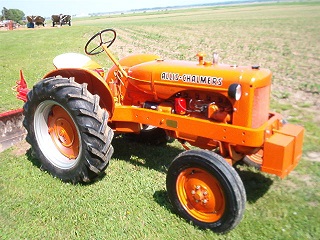
I use the CA and Woods L306 to mow about 2 acres every week. It does a great job and it's fun to use but my old shoulders are tired of the manual steering, so it was time to do something about it. I had thought to add a hydraulic system, but finding a place to mount the pump was a problem I just couldn't solve easily.
Several years ago we built a 1965 Ford Econoline and retrofited it with an electric steering unit and electronic control box from a 2007 Toyota Prius. It worked well except there is no feedback feel from the road and it is a bit different to drive as it will not return to center automaticly by itself, it has to be physically steered. But the steering force required is almost effortless.
I had a couple of units left over from the Econoline build and thought I might adapt the concept to the CA, and since it has to be steered both ways anyhow, the lack of automatic return to center would not be an issue with the tractor.
The result was better than I imagined. Effortless steering.
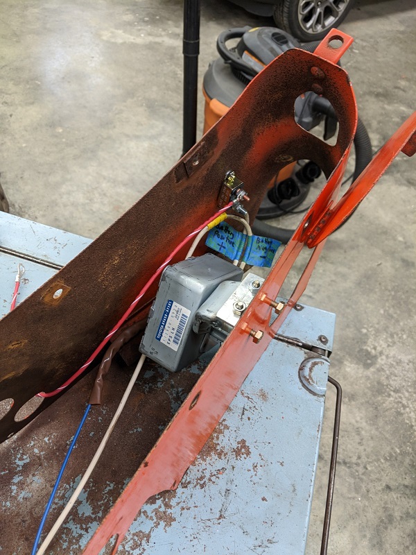
Here are some photos of the project.
|
 |
|
Sponsored Links
|
|
|
jaybmiller
Orange Level Access

Joined: 12 Sep 2009
Location: Greensville,Ont
Points: 24770
|
Post Options
Thanks(0)
Quote Reply
Posted: 18 Apr 2022 at 10:47am |
wow that's NEAT !!
sad you couldn't have hid it under the tank, I know too big....sigh...
|
|
3 D-14s,A-C forklift, B-112
Kubota BX23S lil' TOOT( The Other Orange Tractor)
Never burn your bridges, unless you can walk on water
|
|
steve(ill)
Orange Level Access
Joined: 11 Sep 2009
Location: illinois
Points: 88450
|
Post Options
Thanks(0)
Quote Reply
Posted: 18 Apr 2022 at 1:23pm |
|
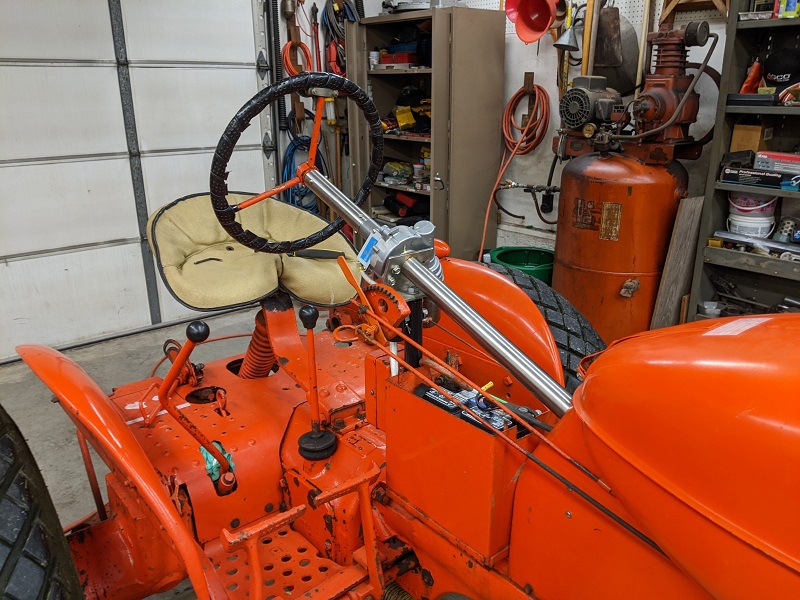
Should work GREAT for your shoulder.... YEP, biggest problem with the B- C CA is there is NO ROOM to do anything, except up by the steering wheel.
|
|
Like them all, but love the "B"s.
|
|
steve(ill)
Orange Level Access
Joined: 11 Sep 2009
Location: illinois
Points: 88450
|
Post Options
Thanks(0)
Quote Reply
Posted: 18 Apr 2022 at 1:27pm |
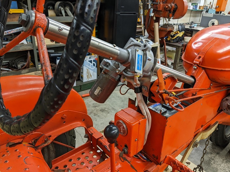
Bret, give a little description of what is going on INSIDE the unit with the ORIGINAL SHAFT.... Did you have to cut the shaft and have an IN and OUT shaft, or is there a gear that slides over the shaft and LOCKS to it that the motor drives ??
You have two wire harnesses by the steering wheel... One for the motor, and is the other a MOVEMENT SENSOR or something like that ? I assume something is talking to the "BOX" in the tool box and it is then telling the MOTOR to rotate ?
Edited by steve(ill) - 18 Apr 2022 at 1:30pm
|
|
Like them all, but love the "B"s.
|
|
Bret (OH)
Silver Level
Joined: 15 Sep 2009
Location: Blanchester, OH
Points: 353
|
Post Options
Thanks(0)
Quote Reply
Posted: 18 Apr 2022 at 4:47pm |
|
Cut steering shaft below electric steering unit. Used a borgeson coupler 11/16-36 spline to 3/4. Machined out to 7/8 for Allis shaft. Welded coupler to shaft. Above unit used Prius shaft, cut keyway for Allis wheel. Can all still be disassembled.
Sensor talks to electric brain box, box sends power to motor according to signal for left or right.
Edited by Bret (OH) - 19 Apr 2022 at 5:45am
|
|
SteveM C/IL
Orange Level Access
Joined: 12 Sep 2009
Location: Shelbyville IL
Points: 8669
|
Post Options
Thanks(0)
Quote Reply
Posted: 18 Apr 2022 at 9:59pm |
|
I'm about function more than appearance. So it looks out of place...but it's not in the way of anything and it WORKS!!!
|
|
steve(ill)
Orange Level Access
Joined: 11 Sep 2009
Location: illinois
Points: 88450
|
Post Options
Thanks(0)
Quote Reply
Posted: 18 Apr 2022 at 10:48pm |
Paint the shaft orange, the motor white and write BUDWEISER on the side of it and nobody will know ! 
|
|
Like them all, but love the "B"s.
|
|
Bret (OH)
Silver Level
Joined: 15 Sep 2009
Location: Blanchester, OH
Points: 353
|
Post Options
Thanks(0)
Quote Reply
Posted: 19 Apr 2022 at 5:43am |
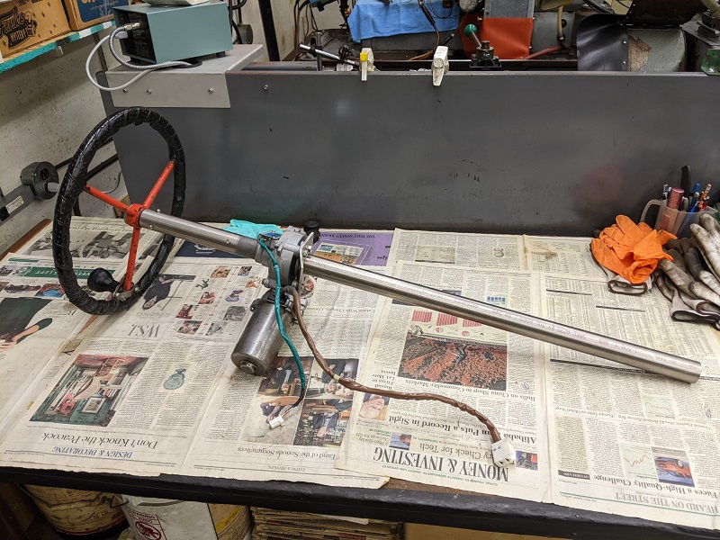
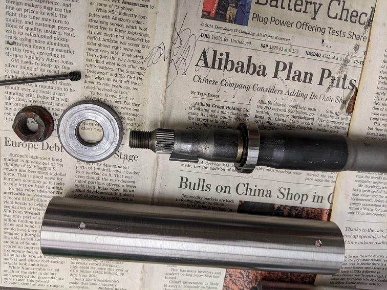
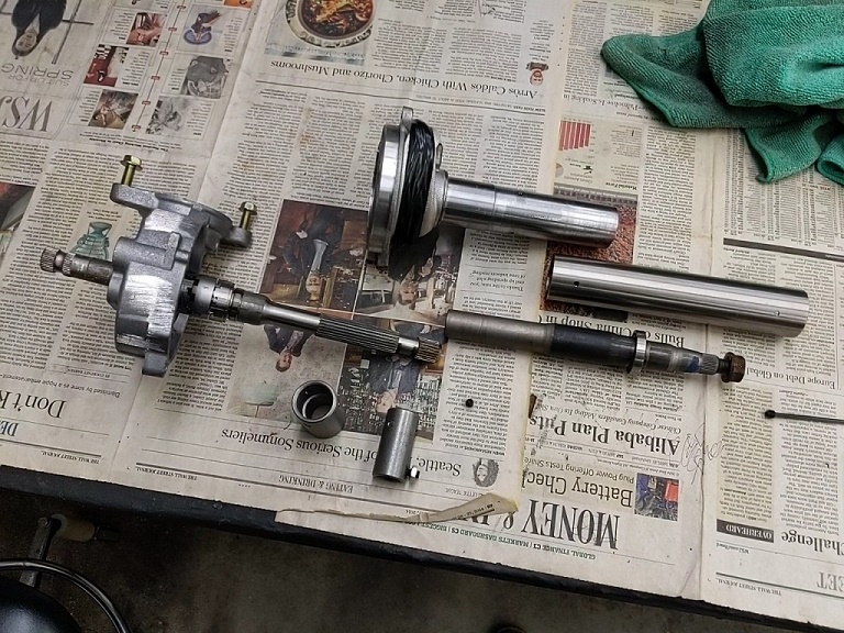
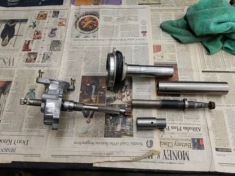
Here are some photos of the components. I machined a secondary coupling for the lower shaft to go over the Borgeson splined coupling that I bored out to .875" since that left the splined coupling thin on the end that fits over the Allis worm shaft. The set screws hold the coupling in place for positioning then after adjustment I welded the couplings together and to the Allis shaft.
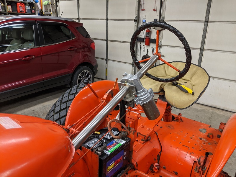
The thick washer goes above the steering wheel as a spacer to allow the Prius nut to tighten the steering wheel onto the upper shaft.
I have ordered a shaft oil seal to be installed at the upper end of the column, just below the steering wheel to seal for water intrusion into the upper bearing on the upper shaft. It's a weird dimension, so I'm not sure the seal I ordered will fit properly. The bore is 1.377, and the shaft is .860. The closest seal I could find is 1.375 x .866.
Edited by Bret (OH) - 19 Apr 2022 at 5:57am
|
|
Jtaylor
Bronze Level

Joined: 11 Oct 2021
Location: Barrie, Ontario
Points: 194
|
Post Options
Thanks(0)
Quote Reply
Posted: 19 Apr 2022 at 8:37am |
Good to see the conversion completed! just need to paint it orange again!
I am currently working on one for the WD and WD45, Should be finished this week.
What Amp circuit breaker are you running? I believe the Prius model pulls about 60A when fully loaded up,
|
|
Bret (OH)
Silver Level
Joined: 15 Sep 2009
Location: Blanchester, OH
Points: 353
|
Post Options
Thanks(0)
Quote Reply
Posted: 19 Apr 2022 at 10:31am |
|
I have a 30 amp installed, but can be increased if needed. I used # 10 wire for the circuit. I haven't mowed with it yet, but it doesn't trip the 30 in the shop. Time will tell.
|
|
Jtaylor
Bronze Level
Joined: 11 Oct 2021
Location: Barrie, Ontario
Points: 194
|
Post Options
Thanks(0)
Quote Reply
Posted: 19 Apr 2022 at 10:40am |
|
If i am not mistaken, the Prius units do normal load around 25 amps, when full lock is applied thats when the amps increase, should be around the 50A mark or so. let us know how it goes!
|
|
desertjoe
Orange Level Access

Joined: 23 Sep 2013
Location: New mexico
Points: 13729
|
Post Options
Thanks(0)
Quote Reply
Posted: 19 Apr 2022 at 3:51pm |
Hey Bret,,,you bet,,!! I am very interested in your project as I'm wanting to modify my D14 as well. Another member, ole Justin, is also doing a similar project on a WD45.
Where did you buy the electrical units to get everything talking to each other,,? You say you used a unit from a 2007 Toyota Prius? The pics you posted of the unit makes the EPS look big for such a small unit,,,, Is your project already completed? MORE pics ,,,,,,,
|
|
desertjoe
Orange Level Access
Joined: 23 Sep 2013
Location: New mexico
Points: 13729
|
Post Options
Thanks(0)
Quote Reply
Posted: 21 Apr 2022 at 7:02pm |
Hello, Bret,,,,what additional electrical parts did you use to be able to "TALK" to the EPS from the Toyota Prius,,,??
|
|
Bret (OH)
Silver Level
Joined: 15 Sep 2009
Location: Blanchester, OH
Points: 353
|
Post Options
Thanks(0)
Quote Reply
Posted: 22 Apr 2022 at 5:05am |
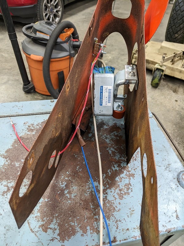
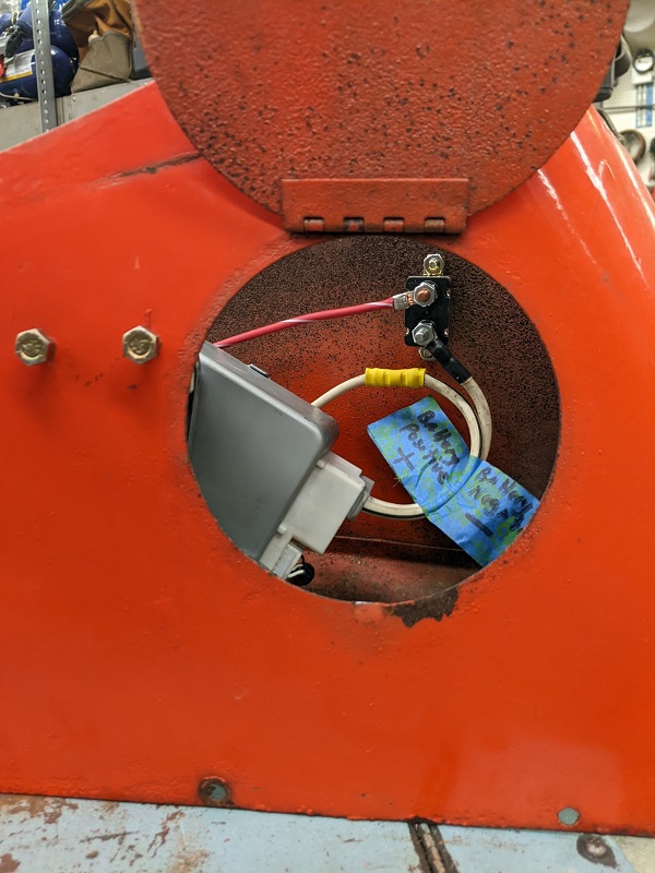
Only (2) toyota parts are needed, the steering assist assembly, and the control box. The control box has 2 large plugs and 2 small plugs. The 2 large plugs are for + and - from the battery, and the power feed wires from the box to the EPU. The 2 smaller connectors are communication wires from the EPU to the control box (the smaller plug as I remember) and a wire from a key on source (the larger small plug) to the control box to tell the box to power on when the key is on, so in this plug only one wire is used and the rest of the pins are ignored. With this setup when the key is first turned on there is a 10 second delay as the unit initializes before power assist is available. Be sure to get the plugs and some wire from the doner car to ease installation. The wires will need to be modified in length to accomodate mounting locations of the components. I also used the upper steering wheel shaft and bearing from the Prius. The steering columns are made from 1 1/2" stainless tubing that I had from another project. Its wall thickness was .060. I bored out the tubing to fit over the CA steering box, and to accept the diameter of the upper bearing and 22X35X7 HMSA10 seal at the steering wheel end. I also bored out the upper tube and turned down the upper extension of the EPU so the 2 parts would fit together to form the upper column.
|
|