| Author |
 Topic Search Topic Search  Topic Options Topic Options
|
MikeSMN 
Silver Level

Joined: 11 Sep 2009
Location: Granada, MN
Points: 122
|
 Post Options Post Options
") Thanks(0) Thanks(0)
 Quote Quote  Reply Reply
 Topic: D17 IV alternator conversion help Topic: D17 IV alternator conversion help
Posted: 29 Oct 2016 at 3:31pm |
|
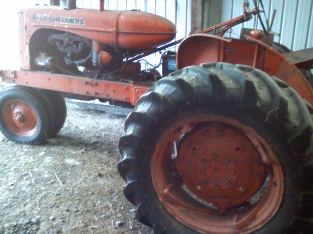
D17 IV 1964 Gas
Was positive ground, generator, key switch and push button start. Have removed generator, old switch, push button start, voltage regulator, old wiring, points, condenser.
Got new stuff from Steve and have tried to follow instructions; obviously wiring is not in my wheel house. Looking for advice from the pros.
Trying to get conversion to negative ground alternator with pertronix ignition working.
Have alternator installed. Have pertronix ignition installed in place of points and condenser. Red wire out of distributor to positive post on the coil. Black wire out of distributor to negative post on cool.
Wire from positive coil post to "power block?" Positive battery cable from here to positive battery post. Wire from here to batt terminal on new ignition switch.
Blue wire from alternator to ign post on switch. Pink wire from ign post on switch to pos post on ammeter. Two red wires from pos post in from alternator on pos post of ammeter. White ground wire from neg post on ammeter grounded to tractor.
Mike
Alternator is plugged in and grounded, wiring harness connected. Battery connected & grounded.
Not even a hint of starting. What am I missing?
|
 |
|
Sponsored Links
|
|
|
MikeSMN
Silver Level
Joined: 11 Sep 2009
Location: Granada, MN
Points: 122
|
Post Options
Thanks(0)
Quote Reply
Posted: 29 Oct 2016 at 5:00pm |
|
Forgot to add that starter is wired to the power block.
|
|
Tcmtech
Orange Level

Joined: 15 Apr 2015
Location: Minot ND
Points: 310
|
Post Options
Thanks(0)
Quote Reply
Posted: 29 Oct 2016 at 5:56pm |
I'm not sure how others do their electrical systems conversion but for me I always start at the battery and work in from there.
First would be the negative terminal to the tractor frame with the appropriately sized cable. Not necessarily hooked up to the battery though. That actual connection comes dead last.
Second would be postive terminal wired to the new starter solenoid or starter button switch that then goes out to the starter with the same appropriately sized cable.
Third would be the heavier gauge wire (not cable) that goes from the battery side of the starter solenoid/button switch to the ammeter negative terminal (if you have one) if not then the main power lug of the power block.
Fourth would be the heavier gauge wire from the positive terminal of the ammeter or power block terminal to the alternator output lug.
Fifth would be the wire that goes from either the ammeter positive terminal (alternator side) or the power block terminal to the ignition switch.
Sixth* (if equipped) the wire from the ignition key/starter solenoid activation button to the starter solenoid.
Seventh** is the wire that feeds the ignition coil (your red wire to the coil postive terminal and ignition module power feed) and the alternator exciter circuit if you have one. (in your case that sounds like the blue wire from the alternator, maybe.) ------------------------------------
* At this point you should be able to temporarily hook up the battery and crank the engine over with the key switch or starter solenoid activation button. It won't start but it will confirm things for the starter circuit are correct and working.
**At this second point you should be able to get power to the ignition coil when the battery is hooked up and ignition switch is turned on and if you have an ammeter see the needle swing negative just a bit from the ignition coil and alternator load. If so and the ignition module is wired correctly, plus has a proper solid ground, you should be able to start the tractor. If not but you do have power to the ignition coil the old points and condenser will still work and allow it to run.
If not retrace your positive circuit from the battery and see where you missed something or have a wire possibly on a wrong connection point being if you haven't done this sortof wiring before it's rather easy to overlook a small detail like that. ------------------------- That's my basic procedure. 
|
|
Sugarmaker
Orange Level
Joined: 12 Jul 2013
Location: Albion PA
Points: 8661
|
Post Options
Thanks(0)
Quote Reply
Posted: 29 Oct 2016 at 6:01pm |
|
Well written procedure!
Thanks!
Regards,
Chris
|
|
D17 1958 (NFE), WD45 1954 (NFE), WD 1952 (NFE), WD 1950 (WFE), Allis F-40 forklift, Allis CA, Allis D14, Ford Jubilee, Many IH Cub Cadets, 32 Ford Dump, 65 Comet, 66 F100.
|
|
Gerald J.
Orange Level
Joined: 12 Sep 2009
Location: Hamilton Co, IA
Points: 5636
|
Post Options
Thanks(0)
Quote Reply
Posted: 29 Oct 2016 at 6:11pm |
|
The white wire from the ammeter is wrong. It doesn't go to ground, it goes to the positive post of the battery, usually connected at the starter solenoid. Otherwise nothing gets powered, no ignition, no starter solenoid and no charging.
Gerald J.
|
|
MikeSMN
Silver Level
Joined: 11 Sep 2009
Location: Granada, MN
Points: 122
|
Post Options
Thanks(0)
Quote Reply
Posted: 08 Jan 2017 at 1:20pm |
Thank you for your replies, I am making progress, slowly and sporadically as time permits. I am still missing something obvious as I can't get the starter to turn or anything on the voltmeter. New battery, new solenoid, new cables to battery and starter, new alternator, new key switch and voltmeter and wiring. Key switch has a start feature, but I would like to keep the push button. My connections aren't working. Looking for some help to point out the obvious so I can move this project along. Thanks again for your help. 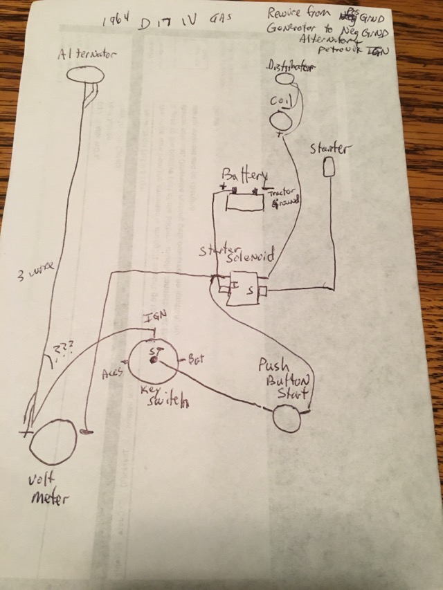
|
|
Brian Jasper co. Ia
Orange Level
Joined: 11 Sep 2009
Location: Prairie City Ia
Points: 10508
|
Post Options
Thanks(0)
Quote Reply
Posted: 08 Jan 2017 at 5:49pm |
|
The coil positive needs to go to the IGN terminal. Whenever the key is in the run and start positions you need power going to the coil. You also need to connect the BATT terminal of the switch to the positive post on the ammeter.
|
|
"Any man who thinks he can be happy and prosperous by letting the government take care of him better take a closer look at the American Indian." Henry Ford
|
|
DennisA (IL)
Orange Level
Joined: 11 Sep 2009
Location: Ridott IL.
Points: 2077
|
Post Options
Thanks(0)
Quote Reply
Posted: 08 Jan 2017 at 6:31pm |
|
This maybe a dumb question, but what is the advantage of switching from a generator to an alternator. I've never had a problem with a generator they always seem to work well.
|
|
Thanks & God Bless
Dennis
|
|
Hawk
Bronze Level

Joined: 04 Aug 2016
Location: King George VA
Points: 10
|
Post Options
Thanks(0)
Quote Reply
Posted: 08 Jan 2017 at 10:42pm |
|
First make the changes that Brian mentioned above. Then it appears in your drawing that you have the push button start switch connected to the start terminal on the key switch. If that is the case you will have to turn the key switch to the start position to make the push button work. You should feed the push button off the ign. or acc. terminal on the key switch, that way the push button will work whenever the key switch is in the run position.
Also you show that you are using a volt meter, It appears that you have it wired as an ammeter. I believe that you have to ground a volt meter to make it read correctly, but i'm not positive about that it has been a while since I hooked one up. Hope this helps!
Edited by Hawk - 08 Jan 2017 at 10:51pm
|
|
Don(MO)
Orange Level
Joined: 12 Sep 2009
Location: Bates City MO.
Points: 6862
|
Post Options
Thanks(0)
Quote Reply
Posted: 09 Jan 2017 at 8:07am |
|
Did you get a new wiring harness from Steve? If you did I'd call Steve he is good to help and happy to do it. I'd be standing beside the tractor when you call and have him walk you one wire at a time, have the Batt. cables off and dash layed back so you can see the back side of it, and just install one wire at a time. This will be the fastest and might save you from having a fire.
|
|
3 WD45's with power steering,G,D15 fork lift,D19, W-Speed Patrol, "A" Gleaner with a 330 corn head,"66" combine,roto-baler, and lots of Snap Coupler implements to make them work for their keep.
|
|
Charlie175
Orange Level
Joined: 11 Sep 2009
Location: Shenandoah, VA
Points: 6369
|
Post Options
Thanks(0)
Quote Reply
Posted: 09 Jan 2017 at 8:16am |
I need to convert my D17 also. The Generator has never been reliable on this one. Standard Alternator won't fit on mine due to the PS Pump location does not give much room. Need to source a smaller one.
|
|
Charlie
'48 B, '51 CA, '56 WD45 '61 D17, '63 D12, '65 D10 , '68 One-Ninety XTD
|
|
DougS
Orange Level

Joined: 03 Nov 2011
Location: Iowa
Points: 2490
|
Post Options
Thanks(0)
Quote Reply
Posted: 09 Jan 2017 at 8:29am |
|
Look for a 40 amp alternator, Charlie. I've seen them new for about $100. Some small Kubota tractors use those, but you'll pay through the nose if you buy from a dealer. Google "small alternator" on the internet.
Cut and paste this:
https://www.amazon.com/DB-Electrical-AND0525-Alternator-Chevrolet/dp/B00KGIDF9Y
Edited by DougS - 09 Jan 2017 at 8:39am
|
|
jaybmiller
Orange Level Access
Joined: 12 Sep 2009
Location: Greensville,Ont
Points: 25237
|
Post Options
Thanks(0)
Quote Reply
Posted: 09 Jan 2017 at 8:48am |
|
'Generally' speaking a generator is a low current----run all day power source while an alternator supplies a lot of power in a short time. So for all day operations like bulldozing or plowing 100 acres(?) a generator will eventually recharge the battery.If you do a lot of 10-15 minute runs, an alternator is best choice.
As for size , the CS130 style(free on 'new' ,old(late 90s) Chevies) is smaller in diameter than the old clunker(early 60s) you see. I didn't have to cut tin ,even used original belt on my D-14s.
One hint about rewiring. Remove and get rid of 100% of the old stuff !! Treat your ride to some new,reliable wiring. either a kit from Steve or DIY. It's not hard or complicated BUT wire Pertonix wrong an poof....you'll need to order anoterh unit!
Jay
|
|
3 D-14s,A-C forklift, B-112
Kubota BX23S lil' TOOT( The Other Orange Tractor)
Never burn your bridges, unless you can walk on water
|
|
Charlie175
Orange Level
Joined: 11 Sep 2009
Location: Shenandoah, VA
Points: 6369
|
Post Options
Thanks(0)
Quote Reply
Posted: 09 Jan 2017 at 9:06am |
Thanks So nothing going in the 2 terminal plug? only the "B" for battery connection?
 DougS wrote: DougS wrote:
Look for a 40 amp alternator, Charlie. I've seen them new for about $100. Some small Kubota tractors use those, but you'll pay through the nose if you buy from a dealer. Google "small alternator" on the internet.
Cut and paste this:
https://www.amazon.com/DB-Electrical-AND0525-Alternator-Chevrolet/dp/B00KGIDF9Y
|
|
|
Charlie
'48 B, '51 CA, '56 WD45 '61 D17, '63 D12, '65 D10 , '68 One-Ninety XTD
|
|
Sugarmaker
Orange Level
Joined: 12 Jul 2013
Location: Albion PA
Points: 8661
|
Post Options
Thanks(0)
Quote Reply
Posted: 09 Jan 2017 at 10:49am |
|
Ok,
Couple observations The original post is from October. I think we need to bare down and help this guy.
Where is Steve?
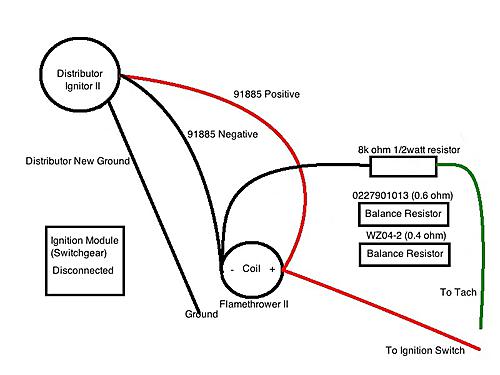
First I have never put on a Petronix system. I am assuming that the extra wire coming out of the distributor to the coil is needed??? Normally there is only a wire in and a wire out of the coil!
Second The alternator is a 3 wire unit by the look of the sketch. The plug on the alternator has two wires and they have to be attached / routed properly, and not to the voltmeter as shown. The red wire coming out of the small plug in goes to the terminaton the alternator. The white wire gets a diode (have to check on the size) installed with the band towards the alternator then goes to accessories terminal of key switch,
I need to go get my hand sketch that I have used for the WD's. Should be about the same except I don't have solenoid.
I am not the expert on these custom but have put together a couple custom systems. Steve at B&B was a big help too! And that is what these are there is no wiring diagram from Allis on this conversion.
BTW I do like the tractors that I have converted to 12v neg ground with alternator. I personally wanted a more robust charging system. Also the systems that were on these tractors were junk! They start really well!
Regards,
Chris
|
|
D17 1958 (NFE), WD45 1954 (NFE), WD 1952 (NFE), WD 1950 (WFE), Allis F-40 forklift, Allis CA, Allis D14, Ford Jubilee, Many IH Cub Cadets, 32 Ford Dump, 65 Comet, 66 F100.
|
|
DougS
Orange Level
Joined: 03 Nov 2011
Location: Iowa
Points: 2490
|
Post Options
Thanks(0)
Quote Reply
Posted: 09 Jan 2017 at 11:58am |
Charlie175 wrote:
Thanks So nothing going in the 2 terminal plug? only the "B" for battery connection? |
If you have an L or an I terminal you would connect that to the ignition switch, through a diode. You can also use a lamp instead of a diode, but that involves drilling a hole in your panel and you stand the risk of the bulb burning out which keeps the alternator from starting its charge.
|
|
steve(ill)
Orange Level Access
Joined: 11 Sep 2009
Location: illinois
Points: 90761
|
Post Options
Thanks(0)
Quote Reply
Posted: 09 Jan 2017 at 12:13pm |
|
|
|
Like them all, but love the "B"s.
|
|
steve(ill)
Orange Level Access
Joined: 11 Sep 2009
Location: illinois
Points: 90761
|
Post Options
Thanks(0)
Quote Reply
Posted: 09 Jan 2017 at 12:19pm |
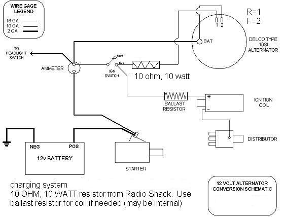
it the drawing above you note a BIG wire on the stud on the back of the alternator. The two small wires on the side plug are HOT and SIGNAL.. The HOT wire can just be jumpered to the BIG wire as it is hot all the time. The small signal wire normally has an inline resistor or diod or bulb to drop voltage slightly to start the alternator charging, and then to stop any BACKFEED when the motor is off...
-
I don't know about your " electronic" distributor, but normally the HOT wire goes to the coil, the coil outlet goes to the distributor, and the distributor is grounded to complete the circuit.. You may need the extra wire shown in your drawing, im not sure.
-
My drawing above uses the normal manual starter switch on the starter case. I will see if I can find a drawing for a solenoid unit...... but the BIG wire to the starter would be cut and one side would go to one BIG terminal on the solelnoid, and the other side of the cut wire would go to the other BIG terminal on the solenoid... there would be two small terminals on the solenoid.. One is power from your start button, the other is normally a ground to the frame.
|
|
Like them all, but love the "B"s.
|
|
steve(ill)
Orange Level Access
Joined: 11 Sep 2009
Location: illinois
Points: 90761
|
Post Options
Thanks(0)
Quote Reply
Posted: 09 Jan 2017 at 12:28pm |
OK, it does appear that the two sides of the coil go to the petronix box in the distributor, and the + side of the coil should be hot when the key is on. .you have it connected to the starter solenoid, should be a HOT wire out of the ign switch.......
Edited by steve(ill) - 09 Jan 2017 at 12:37pm
|
|
Like them all, but love the "B"s.
|
|
steve(ill)
Orange Level Access
Joined: 11 Sep 2009
Location: illinois
Points: 90761
|
Post Options
Thanks(0)
Quote Reply
Posted: 09 Jan 2017 at 12:42pm |
|
you also show the alternator wire going to the volt meter.. that cant happen. Volt meter is a very small size wire in parallel with the alternator or battery to MONITOR the voltage. The BIG wire from the alternator has to go to the BATTERY terminal, unless you have an AMP meter in the line. Your drawing would not look like mine above as I show an AMP METER and you don't have that so go direct to the battery.
|
|
Like them all, but love the "B"s.
|
|
DougS
Orange Level
Joined: 03 Nov 2011
Location: Iowa
Points: 2490
|
Post Options
Thanks(0)
Quote Reply
Posted: 09 Jan 2017 at 12:50pm |
|
Steve's drawing shows the '2' terminal going to the ignition. This is true if you are using a 10SI alternator. Be aware the 10SI is a large alternator. This '2' terminal might be called 'I' or 'L' on other newer alternators. The '1' terminal is called 'S' on newer alternators. It is usually connected internally and does not need to be connected to the BAT or battery. If your alternator had an 'I' and an 'L' terminal you don't need to use both. You can use one or the other though my preference is to use the 'I' terminal when connecting to the ignition and the 'L' terminal when connecting to an alternator charging lamp.
|
|
Sugarmaker
Orange Level
Joined: 12 Jul 2013
Location: Albion PA
Points: 8661
|
Post Options
Thanks(0)
Quote Reply
Posted: 09 Jan 2017 at 12:56pm |
|
I pulled out my wiring diagram for the WD's, but I dont have a solenoid or a starter button switch. So I think someone would need to draw out the diagram with the components that are being used. I also used a volt meter. Some use a ammeter and they are wired differently.
Regards,
Chris
|
|
D17 1958 (NFE), WD45 1954 (NFE), WD 1952 (NFE), WD 1950 (WFE), Allis F-40 forklift, Allis CA, Allis D14, Ford Jubilee, Many IH Cub Cadets, 32 Ford Dump, 65 Comet, 66 F100.
|
|
steve(ill)
Orange Level Access
Joined: 11 Sep 2009
Location: illinois
Points: 90761
|
Post Options
Thanks(0)
Quote Reply
Posted: 09 Jan 2017 at 1:07pm |
Mike, you need something like this.......... I just threw it together real quick so maybe 95% correct.. should get you started and you can ask the guys about details as you go.
|
|
Like them all, but love the "B"s.
|
|
steve(ill)
Orange Level Access
Joined: 11 Sep 2009
Location: illinois
Points: 90761
|
Post Options
Thanks(0)
Quote Reply
Posted: 09 Jan 2017 at 1:11pm |
|
your original drawing shows the key switch connected to the ignition and start terminals... you power should come in on the BAT terminal and go out on the IGN terminal... the "start" terminal is when you turn the key PAST the ignition point.. you don't need that, your going to use the push button to start. ......... some solenoids have two small terminals, some have one... need to figure out which one you have and which one is the HOT wire.. the two BIG lugs don't matter which BIG wire is on each.
|
|
Like them all, but love the "B"s.
|
|
Steve in NJ
Orange Level Access
Joined: 12 Sep 2009
Location: Andover, NJ
Points: 12071
|
Post Options
Thanks(0)
Quote Reply
Posted: 09 Jan 2017 at 7:14pm |
|
Mike,
Gimme a call tomorrow. I'd be happy to walk ya through it. Didn't know you were having trouble. Its not tough. I've been on and off the forum a lot due to a shoulder tear. Been in and out of the Docs office a lot lately...
Steve@B&B
|
|
39'RC, 43'WC, 48'B, 49'G, 50'WF, 65 Big 10, 67'B-110, 75'716H, 2-620's, & a Motorhead wife
|
|
Ted J
Orange Level

Joined: 05 Jul 2010
Location: La Crosse, WI
Points: 18962
|
Post Options
Thanks(0)
Quote Reply
Posted: 10 Jan 2017 at 5:59am |
steve(ill) wrote:
Mike, you need something like this.......... I just threw it together real quick so maybe 95% correct.. should get you started and you can ask the guys about details as you go. |
Steve, you left out the voltmeter and/or ammeter. Where does that go?
|
|
"Allis-Express"
19?? WC / 1941 C / 1952 CA / 1956 WD45 / 1957 WD45 / 1958 D-17
|
|
Sugarmaker
Orange Level
Joined: 12 Jul 2013
Location: Albion PA
Points: 8661
|
Post Options
Thanks(0)
Quote Reply
Posted: 10 Jan 2017 at 10:18am |
|
Similar to what I have done. You need to lay out each electrical item in the system. The wiring will be different in each custom system.
Sounds like B&B may be able to help also since you got some of the components from him. He has been a lot of help as I did my WD's. Looks simple after completed.
Regards.
Chris
|
|
D17 1958 (NFE), WD45 1954 (NFE), WD 1952 (NFE), WD 1950 (WFE), Allis F-40 forklift, Allis CA, Allis D14, Ford Jubilee, Many IH Cub Cadets, 32 Ford Dump, 65 Comet, 66 F100.
|
|