| Author |
 Topic Search Topic Search  Topic Options Topic Options
|
Mdguy 
Bronze Level

Joined: 08 Feb 2020
Location: MD
Points: 30
|
 Post Options Post Options
") Thanks(0) Thanks(0)
 Quote Quote  Reply Reply
 Topic: D17 alternator conversion Topic: D17 alternator conversion
Posted: 28 Dec 2020 at 2:28pm |
|
Switching my series 3 D17 to 12 volt negative ground with an alternator. Tractor was currently wired correctly like is in manual. 1 wire alternator ran that(charging wire)through voltmeter. Other terminal of voltmeter went to starter solenoid where battery cable is. The original diagram has a jumper wire from voltmeter to starter switch. When I have hooked the battery up the hydraulic indicator light comes on. Even with key off. What do I need to do to fix this problem. Or does anyone have a diagram they have used before.
Thanks
And reason I am doing this is because I’ve replaced 3 voltage regulators from nephews who have borrowed a battery and hooked up wrong. Even after they have been told bout it. I figure this be easier. No more repolorizing the generator or external regulators to worry about
|
 |
|
Sponsored Links
|
|
|
steve(ill)
Orange Level Access

Joined: 11 Sep 2009
Location: illinois
Points: 89106
|
Post Options
Thanks(0)
Quote Reply
Posted: 28 Dec 2020 at 4:22pm |
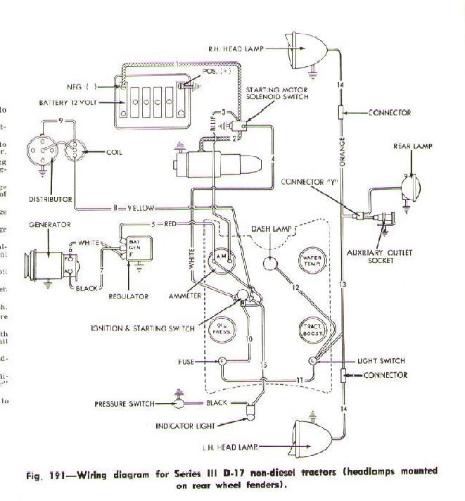
Below is a drawing of the D17 wire. I think you are talking about #15 the black wire at the bottom left ... it runs a light bulb if the pressure switch is closed .. (Pressure from power director ?)
If you have power with the switch OFF, then you have the hot wire on the wrong side of the switch so it is always hot..should be with the yellow wire that feeds the coil... only hot with KEY on.... also you might have a second problem.. The light should not go on unless the pressure switch is grounded ? Switch is broke or wire is touching ground.
Edited by steve(ill) - 28 Dec 2020 at 4:24pm
|
|
Like them all, but love the "B"s.
|
|
Mdguy
Bronze Level
Joined: 08 Feb 2020
Location: MD
Points: 30
|
Post Options
Thanks(0)
Quote Reply
Posted: 28 Dec 2020 at 5:10pm |
|
Thanks for the reply. I did realize that 2 wires were switched like you said. Without the jumper wire to the key switch the tractor will not start or even crank over. Hook that jumper wire up tractor starts up. Problem is as soon as hook battery up to cable(key off) with a test light the alternator has juice running to it. I’m guessing getting back fed from battery through voltmeter back to alternator.
And it could be a 1 wire alternator but I’m putting a dummy light on the dash(or would like to) so I can tell if something is not working right. It’s a small alternator I saw on here somebody had posted. Watching the YouTube video bout it (and guy even put it on an old allis diesel) looked so simple.
I usually think it’s a good idea to start these “simple projects”and then I screw up somewhere along the way and spend 4 days trying to figure it out and then pay somebody to fix my screw ups.
|
|
steve(ill)
Orange Level Access
Joined: 11 Sep 2009
Location: illinois
Points: 89106
|
Post Options
Thanks(0)
Quote Reply
Posted: 28 Dec 2020 at 5:15pm |
a ONE WIRE alternator only has a BIG cable like 8 gauge that runs from the alternator to the amp meter... There is non LIGHT... If you are using one of the SMALL terminals on the alternator, then it is either NOT a 1 wire alternator, or you got too many wires involved.... all its excitation and regulation is done INTERNAL.
The KEY connects the amp meter wire to the coil wire... the Hydraulic wire should not be part of that circuit. ... but does connect to the same coil wire terminal on the key.
are you using a VOLT METER or an AMP METER ?
Edited by steve(ill) - 28 Dec 2020 at 5:25pm
|
|
Like them all, but love the "B"s.
|
|
Steve in NJ
Orange Level Access

Joined: 12 Sep 2009
Location: Andover, NJ
Points: 12034
|
Post Options
Thanks(0)
Quote Reply
Posted: 28 Dec 2020 at 6:10pm |
You should be running power to the Alternator through a key switch. This way you control power on board the Tractor. Run your Battery feed from the Starter motor to the BAT terminal of the key switch, and then run a wire to the VR #1 terminal at the Alternator from the IGN terminal or ACC on the key switch. Install a wire from the plus (+) side of the Voltmeter and run it to #2 terminal at the Alternator. This is your "voltage sense" wire which will monitor current usage on board the Tractor and ramp the Alternator up when current is being used to keep the Battery happy as well as feeding power to the system. You just made a 3 wire system out of your one wire Alternator. Leave the one wire Alt's to Cars, Trucks n' Hotrods. In the #1 terminal wire, you may need to install a 50 volt/1 amp diode so the engine shuts off. If you use an Ignition switch that is equipped with an ACC terminal, sometimes you can run the #1 VR wire off of that terminal and a diode may not be needed. We have all the parts in stock if you need anything... HTH Forgot to mention. Run a jumper wire from the IGN terminal on the key switch to the plus (+) side of the Voltmeter. This completes the circuit at the other end. It also will show you standing Battery voltage when the key is turned to the ON position.
Steve@B&B bb-customcircuits.com
Edited by Steve in NJ - 28 Dec 2020 at 6:12pm
|
|
39'RC, 43'WC, 48'B, 49'G, 50'WF, 65 Big 10, 67'B-110, 75'716H, 2-620's, & a Motorhead wife
|
|
DSeries4
Orange Level

Joined: 12 Sep 2009
Location: Ontario, Canada
Points: 7564
|
Post Options
Thanks(0)
Quote Reply
Posted: 28 Dec 2020 at 7:05pm |
|
Series 3 is already 12 volts from the factory with a positive ground. All you need to do is switch it to negative ground. No need for an alternator and a bunch of new wiring. Switch the battery cables on the posts, switch the wires around on back of the ammeter, switch the 2 wires on the coil. Re-flash the generator and you are done.
|
|
'49 G, '54 WD45, '55 CA, '56 WD45D, '57 WD45, '58 D14, '59 D14, '60 D14, '63 D15D, '66 D15II, '66 D21II, '67 D17IV, '67 D17IVD, '67 190XTD, '73 620, '76 185, '77 175, '84 8030, '85 6080
|
|
steve(ill)
Orange Level Access
Joined: 11 Sep 2009
Location: illinois
Points: 89106
|
Post Options
Thanks(0)
Quote Reply
Posted: 28 Dec 2020 at 8:02pm |
I agree with Steve on the 3 wire alternator.. Much better setup.. Here is a drawing of what he is talking about... but i have an amp meter instead of volt meter.
|
|
Like them all, but love the "B"s.
|
|