| Author |
 Topic Search Topic Search  Topic Options Topic Options
|
ac55tractor 
Silver Level

Joined: 20 Oct 2012
Location: Raymond, Maine
Points: 240
|
 Post Options Post Options
") Thanks(0) Thanks(0)
 Quote Quote  Reply Reply
 Posted: 24 Dec 2021 at 10:46am Posted: 24 Dec 2021 at 10:46am |
|
I found another set of connecting rods where the cap was mismatched. I numbered the piston rods as I pulled them out. I have just renumbered them. I can understand were people who do there best when working on their tractors can easily make a mistake and mismatch parts. This is not an easy process and nobody is any better than anyone else. I would have never noticed the mismatch without the support that I received here from the forum. This is an amazing resource. I feel very fortunate.
|
 |
|
Sponsored Links
|
|
|
steve(ill)
Orange Level Access

Joined: 11 Sep 2009
Location: illinois
Points: 90834
|
Post Options
Thanks(0)
Quote Reply
Posted: 24 Dec 2021 at 12:17pm |
YEP.... good idea to center punch the rod and cap near the bolt area prior to removal of each cap.. So, if you have the right caps on the right rods now, do the NUMBERS come out OK or do you still have to machine them ? I think factory "original" the cap was mounted to the rod and machined to size, so they have to be a "matched set".
Sounds like your on the right track now !!
|
|
Like them all, but love the "B"s.
|
|
SteveM C/IL
Orange Level Access
Joined: 12 Sep 2009
Location: Shelbyville IL
Points: 8982
|
Post Options
Thanks(0)
Quote Reply
Posted: 24 Dec 2021 at 1:50pm |
|
Uh ,yeah, you always make sure the cap and rod are marked as a set before separation. Many already are. Older stuff not so much.
|
|
ac55tractor
Silver Level
Joined: 20 Oct 2012
Location: Raymond, Maine
Points: 240
|
Post Options
Thanks(0)
Quote Reply
Posted: 24 Dec 2021 at 2:40pm |
Yes I have to re machine the bores. I am not an engineer, or at times the brightest bulb on the Christmas tree. There are a lot of things that I just don't understand, there has to be a reason why the bores on these rods become out of round. There is plenty of material there. I just checked them and they are all out of round at different amounts, within a few thousandths.
Lon(MN) said "All the rods I have sent out were egg shaped."
So it looks as if I am not the only one that have had this issue.
My guess is that Steve (ill) is right, they must be mounted together and machined to size. When this is done there is no real concern for how they go together, just as long as the bore is to size and perpendicular (square) to the outside machined edges of the bore. It's really just a cost savings for the factory.
I have a plan to repair the connecting rods. If anyone is interested, I will post it.
I have done quite a few things at work, in the shop, and I became really resourceful.
Fortunately, I have a good memory.
I am not a know it all. If I don't know something, I will be the first to tell you.
Steve form Maine
|
|
ac55tractor
Silver Level
Joined: 20 Oct 2012
Location: Raymond, Maine
Points: 240
|
Post Options
Thanks(0)
Quote Reply
Posted: 24 Dec 2021 at 10:26pm |
Well, It’s Christmas eve. I have just
done some research. It seems that connecting rod and bearing bore stretching is
not uncommon. I found dozens of webpages describing how and why it happens.
Basically, it's all in the nature of an internal combustion engine. Pistons go
up and down and connecting rods, and bearing bores get stretched in the process. From what I've
found, it's been going on for over 100 years now. They say the best way to
correct a stretched connecting rod is to replace it. That leaves most of us vintage
Allis Chalmers owners in a bad place. I don't think that they are stamping out
any new connecting rods for our tractors in Milwaukee, Wisconsin or anywhere
else.:)
Okay, I know, I'm having a little fun,
and I am getting off topic here.
Fortunately, I received a message from a very wise
man tonight. He said, “This isn't a Nascar engine.” He’s right.
I will start a new post when I get started on reworking the connecting rods.
The crankshaft end play is fixed.
Merry Christmas and good night to all.
Steve from Maine
|
|
Joe(TX)
Orange Level

Joined: 11 Sep 2009
Location: Weatherford. TX
Points: 1682
|
Post Options
Thanks(0)
Quote Reply
Posted: 27 Dec 2021 at 2:18am |
|
All the rods will be egg shaped without shims. this will allow the shim thickness to be adjusted for bearing wear.
|
|
1970 190XT, 1973 200, 1962 D-19 Diesel, 1979 7010, 1957 WD45, 1950 WD, 1961 D17, Speed Patrol, D14, All crop 66 big bin, 180 diesel, 1970 170 diesel, FP80 forklift. Gleaner A
|
|
ac55tractor
Silver Level
Joined: 20 Oct 2012
Location: Raymond, Maine
Points: 240
|
Post Options
Thanks(0)
Quote Reply
Posted: 27 Dec 2021 at 7:07pm |
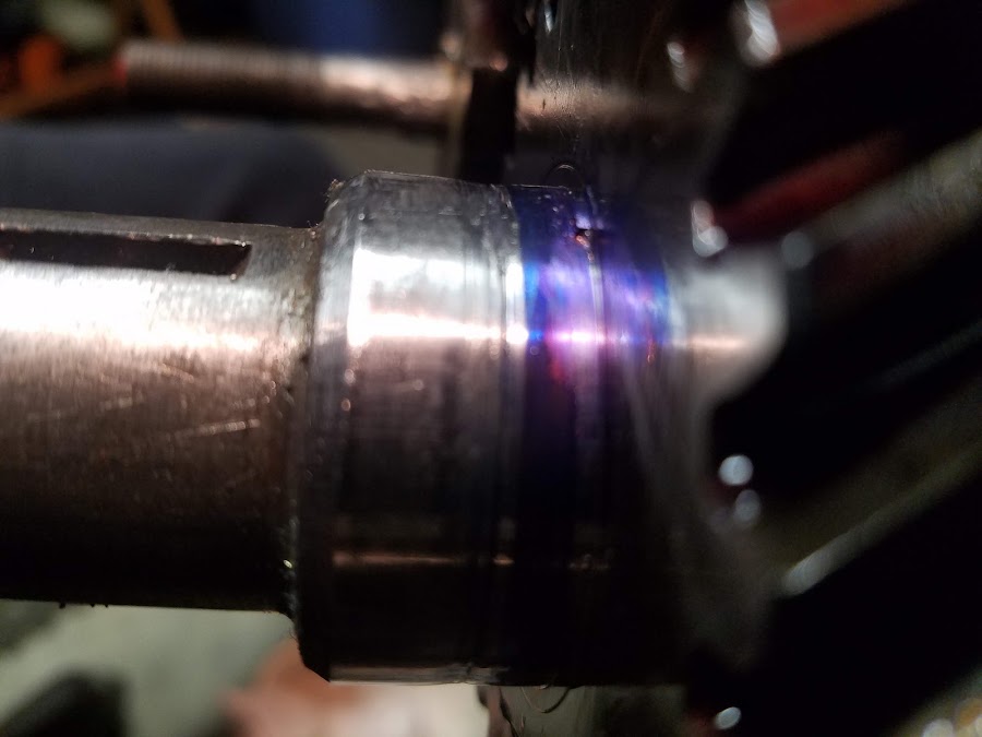
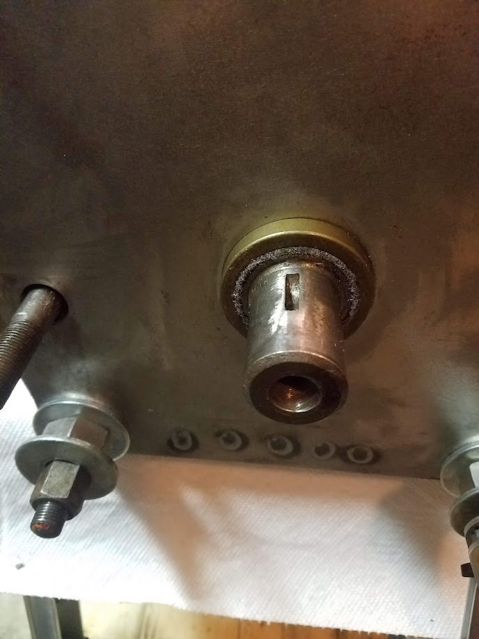
I do not disagree with you. I approached this with an open
mind today. After a lot of measuring, it seems that no matter what I do, I
cannot increase the distance shown with the arrow in the picture. This distance
remains at 1.925. I can add as much sim as I want, and it still won't increase
the 1.925 distance across. All the bearing journals on the crank shaft have
been ground down to 1.927 or -.010 from the original dimensions.
When I hand tighten the rod nuts to any of the rods, with
any combination of bearing, and matched shims to any of the journals on the
crank shaft, the area above and below the mating edges of the bearing will only
make contact and rub in the area shown in the picture. If I "snug"
the connecting rod to the crankshaft with a wrench, the rod will not move.
Please feel free to ask any questions. I want to get to the bottom of this
before I cut the bearing bores to fit the new bearings.
Respectfully
Steve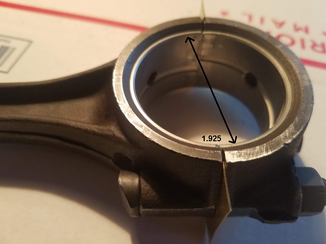
|
|
steve(ill)
Orange Level Access
Joined: 11 Sep 2009
Location: illinois
Points: 90834
|
Post Options
Thanks(0)
Quote Reply
Posted: 27 Dec 2021 at 7:45pm |
I dont think anyone disagrees with your analysis... You need a couple thousandths clearance between the bearings and crank.. No matter how many SHIMS you add, you are not going to increase the horizontal dimension of the bearing.... Remachine is the only way.
How it got "TOO SMALL" is unknown at this point.. I did not look up the "factory" dimensions of the rod or crank to verify numbers... At this point it dont matter.
Edited by steve(ill) - 27 Dec 2021 at 7:47pm
|
|
Like them all, but love the "B"s.
|
|
ac55tractor
Silver Level
Joined: 20 Oct 2012
Location: Raymond, Maine
Points: 240
|
Post Options
Thanks(0)
Quote Reply
Posted: 27 Dec 2021 at 8:04pm |
No worry''s, I have all the hard copy manuals.
Thanks for everything .
|
|
SteveM C/IL
Orange Level Access
Joined: 12 Sep 2009
Location: Shelbyville IL
Points: 8982
|
Post Options
Thanks(0)
Quote Reply
Posted: 27 Dec 2021 at 11:18pm |
|
Around here rods are sent to the machine shop where they torque em down and hone the bore round. I don't think they generally have to remove any material at parting line. I'm no expert on this but that is my understanding.
|
|
ac55tractor
Silver Level
Joined: 20 Oct 2012
Location: Raymond, Maine
Points: 240
|
Post Options
Thanks(0)
Quote Reply
Posted: 28 Jan 2022 at 12:03pm |
") steve(ill) wrote: steve(ill) wrote:
i had a similar problem on a B ... 15 years ago... cant give you exact numbers, but i took the gear off and machined a STEP on the back of the gear so i could push it on about .040 further to get the dimension right for the bearing... you want something small like .002 or .005 clearance .............. The gear is about an inch wide, pushing it on .040 further don't hurt the gear alignment to others. |
I have been very ill. It's not covid. Going for tests next week. Overhaul on hold for over a week now.
I wanted to take the time to say thanks to Steve (ill) for the heads up with my crankshaft gear and the rework that can be done. When I sent the crankshaft out, the guy who ground it assumed that the thrust bearing width was 1.625. So he machined a gap to 1.630. Come to find out, the thrust bearing was 1.620. That will give me .010 shaft end play. Instead of bringing the crank back to him, I am going to undercut the gear .005 - .007 and install the gear and call it good. Thanks again Steve(ill)
Steve (inME)
|
|
DrAllis
Orange Level Access
Joined: 12 Sep 2009
Points: 22821
|
Post Options
Thanks(0)
Quote Reply
Posted: 28 Jan 2022 at 12:14pm |
|
.010" crank endplay ?? I wouldn't lose one seconds sleep over that. Run it.
|
|
ac55tractor
Silver Level
Joined: 20 Oct 2012
Location: Raymond, Maine
Points: 240
|
Post Options
Thanks(0)
Quote Reply
Posted: 28 Jan 2022 at 12:19pm |
Thanks, DrAllis One less thing to worry about, :)
Steve (inME)
|
|
SteveM C/IL
Orange Level Access
Joined: 12 Sep 2009
Location: Shelbyville IL
Points: 8982
|
Post Options
Thanks(0)
Quote Reply
Posted: 28 Jan 2022 at 9:27pm |
|
Take the time out to get your health back. Without that,nothing else matters much.
|
|
ac55tractor
Silver Level
Joined: 20 Oct 2012
Location: Raymond, Maine
Points: 240
|
Post Options
Thanks(0)
Quote Reply
Posted: 29 Jan 2022 at 10:56am |
Thanks SteveM C/IL for your kind advice. I realize that the forum is not really the place for medical issues. All points are leading to what is called diverticula. You can Google it. I am feeling a little better this morning. I have some things that I want to pass along on the "Connecting rod "rework" page. I will try to post over there later on today or tomorrow. Sending my best to everyone at the Allis Chalmers forum.
Steve (inME) |
|
ac55tractor
Silver Level
Joined: 20 Oct 2012
Location: Raymond, Maine
Points: 240
|
Post Options
Thanks(0)
Quote Reply
Posted: 19 May 2022 at 8:43pm |
Hi Everyone.
I just wanted to say how grateful I am
to the forum, to Steve(ill), Paul B, Steve M C/IL, and all the others. I
feel that their guidance is paying off. After my crankshaft was reground, roughly .040 was removed and cleaned up from the “thrust area” that had warn off,
on crankshaft.
After applying blue to the front seal journal. and with the front seal installed, I aligned the plate on the front of the engine and spun the crankshaft. From what I
can see, the seal is riding on a clean un-warn area of the seal journal. In the end the rework has appeared to have moved the
crankshaft forward making a new contact area for the front seal to ride. Or, is an easy sleeve still going to be needed here? Thanks Steve
|
|
DrAllis
Orange Level Access
Joined: 12 Sep 2009
Points: 22821
|
Post Options
Thanks(0)
Quote Reply
Posted: 19 May 2022 at 8:49pm |
|
Only reason for a speedi-repair sleeve is to cover up worn in groove on a shaft. You've moved the groove out of the path of wear. Why would you need it ??
|
|
ac55tractor
Silver Level
Joined: 20 Oct 2012
Location: Raymond, Maine
Points: 240
|
Post Options
Thanks(0)
Quote Reply
Posted: 19 May 2022 at 9:08pm |
Thanks for your reply DrAllis. I have never heard of an easy sleeve until
just recently. Most of this is new to me. I really have struggled through a lot of this rebuild. I really just want this to be a one and done. I'm sure that you can
understand. Steve
|
|
steve(ill)
Orange Level Access
Joined: 11 Sep 2009
Location: illinois
Points: 90834
|
Post Options
Thanks(0)
Quote Reply
Posted: 19 May 2022 at 9:49pm |
|
I would agree, no sleeve... the big question is WHY did the crank move that much ? It looks like a quarter inch ?
Edited by steve(ill) - 19 May 2022 at 9:50pm
|
|
Like them all, but love the "B"s.
|
|
ac55tractor
Silver Level
Joined: 20 Oct 2012
Location: Raymond, Maine
Points: 240
|
Post Options
Thanks(0)
Quote Reply
Posted: 19 May 2022 at 10:00pm |
Steve Can you please look at the start of this post and I am sure it will all came back to you.
Thanks
Steve (in-ME)
|
|
steve(ill)
Orange Level Access
Joined: 11 Sep 2009
Location: illinois
Points: 90834
|
Post Options
Thanks(0)
Quote Reply
Posted: 19 May 2022 at 10:51pm |
Steve, i thought you had the face machined and the gear pushed on .037 inch to get the bearing thrust clearance back to spec... I can see the "groove" moving 30 thousands, but doubt you could see that... The photo looks like it move 1/4 inch , unless i am looking at the groove wrong ?? ......... I would be more inclined to believe the seal is setting different in the housing, or the seal is "different" than original ?
I dont think there is room in the block to move the crank 1/4 inch and still get the connecting rods installed ?
Edited by steve(ill) - 19 May 2022 at 10:53pm
|
|
Like them all, but love the "B"s.
|
|
ac55tractor
Silver Level
Joined: 20 Oct 2012
Location: Raymond, Maine
Points: 240
|
Post Options
Thanks(0)
Quote Reply
Posted: 20 May 2022 at 2:02pm |
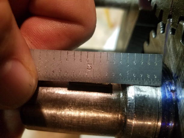
Steve
Maybe this will help. It was hard to get this
picture with my phone, but I'm sure you get the idea. I used a
Machinist's scale, from Starrett. Each line is .010. It shows roughly .040 from the old ware groove to the end of the blue. I only blued where
the old seal was up to the crank gear to check for seal contact. You are right, the
front seal that came with the gasket kit is not at all like the
original. The contact area on the new seal is also roughly .032. After some searching this morning the seal is for D10, D12, D14, D15 Allis. It does seem to fit the application without any interference from the lower belt pulley. All of the other gaskets from the kit fit just fine. The gasket kit was for a B so I got it. There were some extra gaskets with the kit that I didn't recognize, but the ones that I needed were included. I am not using the head gasket from that kit. It's marked China. I have a Fel-Pro head gasket kit Part # HS-7378B that I will be using. There was another thin front lip seal that came with the kit, it was larger in diameter than the original. I did come across some postings where some guys were using J.B. Weld. I just didn't know what would be best in this case. As always, Thanks
Steve (inME)
|
|