| Author |
 Topic Search Topic Search  Topic Options Topic Options
|
dfwallis 
Orange Level

Joined: 09 Mar 2023
Location: Texas / Indiana
Points: 958
|
 Post Options Post Options
") Thanks(0) Thanks(0)
 Quote Quote  Reply Reply
 Posted: 08 Jun 2025 at 3:42pm Posted: 08 Jun 2025 at 3:42pm |
|
DSpears N IL, yes I believe I saw those pics in my research. I like it. If I can't identify a ROPS suitable attachment that still allows me to rapidly reconfigure to pin-hitch implements, I may do something like that. Your pics may be where I got the idea from :) I like the hard shell canopy better than the canvas, but I haven't finally decided anything yet.
|
|
1952 CA13092, CA Pickup Plow, CA Cultivator, CA Two Row Planter, Dunham-Lehr GC78 Disc, Grader Blade, 3pt Fm180 Finish Mower
|
 |
|
Sponsored Links
|
|
|
dfwallis
Orange Level
Joined: 09 Mar 2023
Location: Texas / Indiana
Points: 958
|
Post Options
Thanks(0)
Quote Reply
Posted: 08 Jun 2025 at 4:00pm |
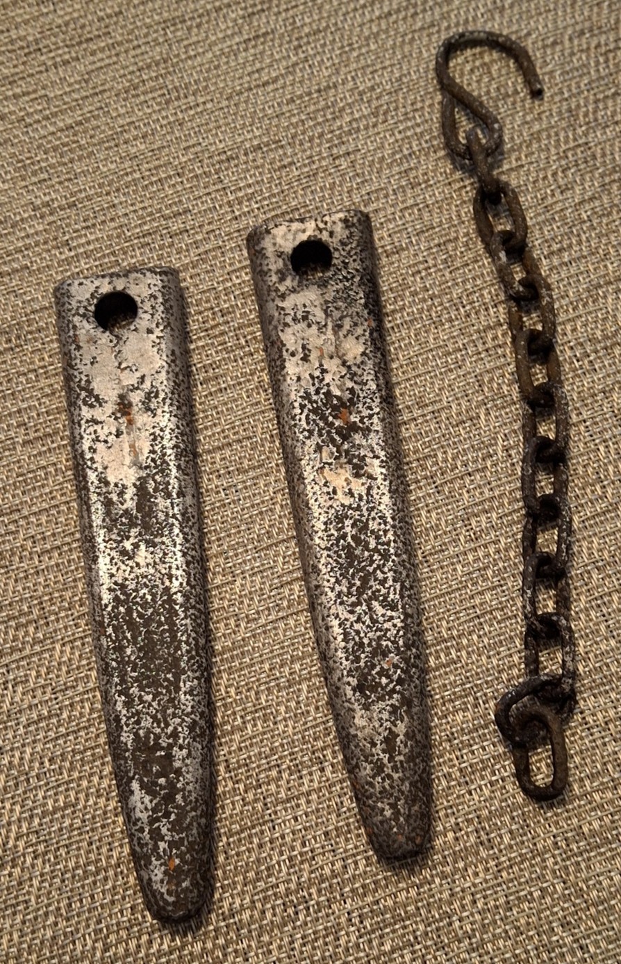
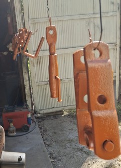
I worked on the wedge pins to clean them up and paint them. Wire brushed, sanded, wire brushed, and soaked (washed in dish soap a few times too). I left a few specs of original paint on for character :). I didn't spend much time on the chain since it's a spare. I just coated with primer for safekeeping. If anybody might need one, I might part with it. I believe it is in pretty good shape with 12 links:
I only soaked them for about 4 hours. I'm not sure if the WD40 version is the same as Evaporust or not. Seems similar in performance.
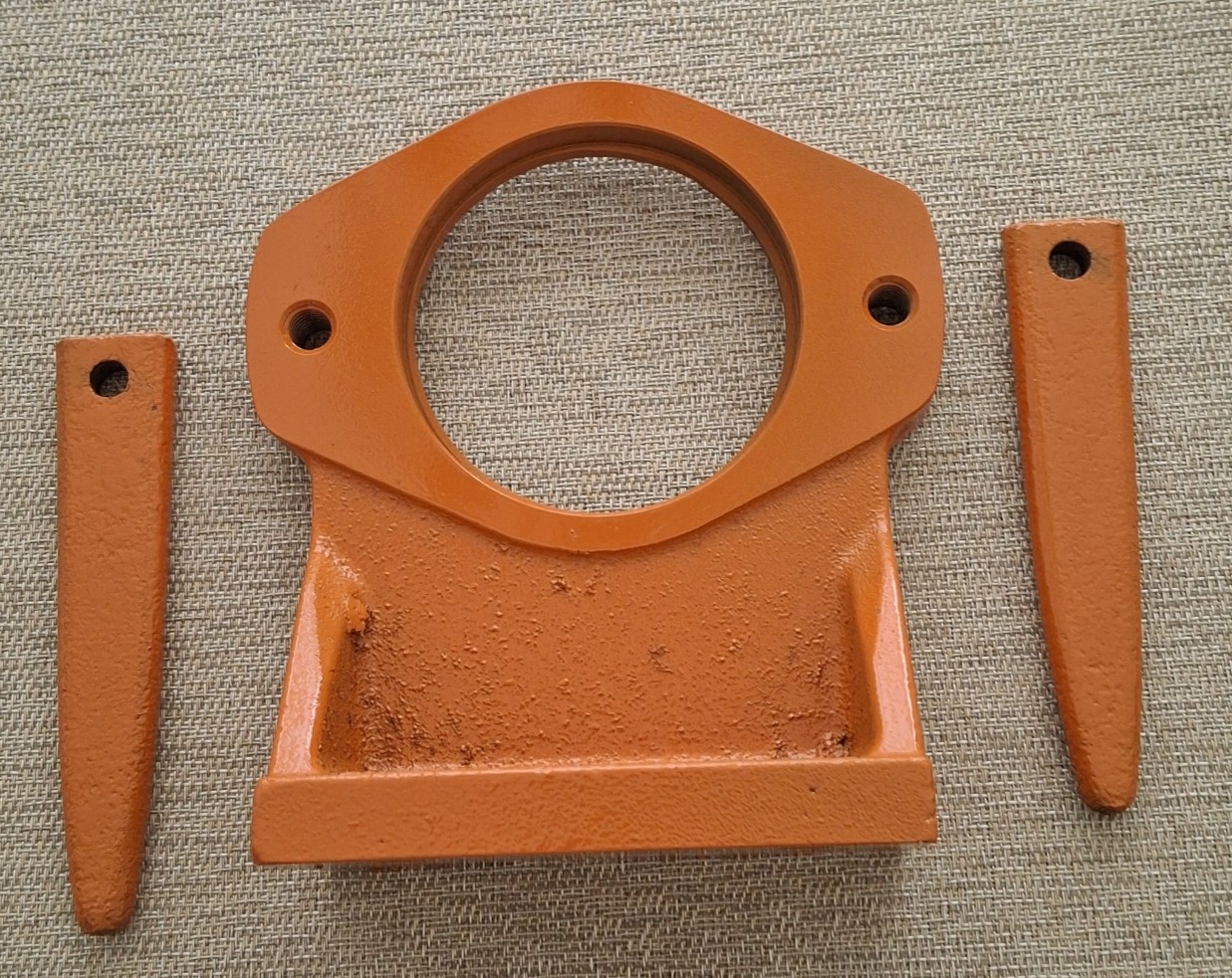
Painted the wedges and the SAE-B hydraulic pump mount. I noticed a few missed spots and took it back out to touch them up after the pic. Was too dark in the garage when I painted. The mount is aluminum. The paint will probably interfere with pump mounting. I'll fix that later if needed.
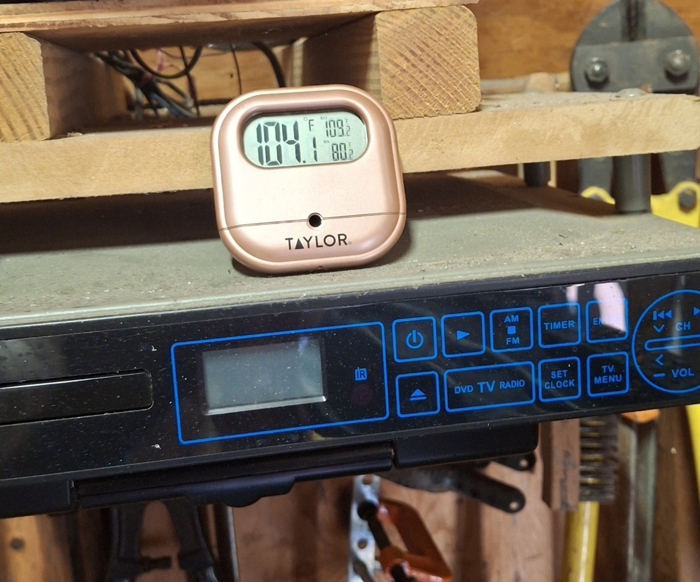
My workshop in TX is typically slightly more toasty than the one in IN. After I turned on some fans to bring in outside air it went "down"...to 106 :( As long as a fan is blowing directly on me, not too bad.
|
|
1952 CA13092, CA Pickup Plow, CA Cultivator, CA Two Row Planter, Dunham-Lehr GC78 Disc, Grader Blade, 3pt Fm180 Finish Mower
|
|
dfwallis
Orange Level
Joined: 09 Mar 2023
Location: Texas / Indiana
Points: 958
|
Post Options
Thanks(0)
Quote Reply
Posted: 03 Aug 2025 at 8:00pm |
08/03/2025 Status:
1) After contacting the vendor of the GTC505 analyzer, I discovered that they have a firmware update that relates to misinterpreting mechanical distributor signals that don't quite transition to zero volts between firings (I assume trigger not resetting due to not seeing the required voltage transition). After installing the 211C update, the electrical misfires were completely eliminated.
So I went back to assuming carburetor issues. I found a cheap knockoff zenith (advertised as a replacement, but I believe somebody made a copy/paste error as it was not the correct model to replace a TSX486). Anyway, the new carburetor completely eliminated the misfires at idle. I had cleaned and replaced about everything in the TSX486 (had it apart about 12 times), but something is still wrong, so I sent it out for a "professional" rebuild. I'll try it out next trip in late August (2025). As for the knockoff zenith, I had to bore the (stepped) main jet out from 0.0645/.0600 all the way to 0.0990 before the tractor would run above idle (the TSX486 is at 0.0990 #39 drill). Was severely gas starved at anything above idle. These zenith "universal" carburetors are horrible. They have small diameter mounting studs that allow the carburetor to be misaligned causing the throttle plate to get stuck rubbing against the flange hole (maybe the reason for extra gaskets, but there were no instructions). Also, you have to cut off and grind the throttle rod, else it won't mount and even grinding it all the way to the lock nut, it still rubs the block when it rotates. I don't recommend anybody use these if there's any way around it. Find a proper TSX and stick with it. Also, if you DO install the zenith, you MUST modify it (on a CA), which then makes it non-returnable.
Edit: I've decided that I could probably just bore the zenith mounting stud holes out to the correct size and use the TSX mounting bolts and nuts. That should eliminate the alignment issues. Was slightly scary when the tractor revved up uncontrollably a few times :(
2) Spent some time on the hydraulic pump bracket. I completed the design of the bracket for the front (dual mount front or at the belt pulley). Unfortunately, the 5 inch engine pulley I got won't work because the 1 inch spline is too large to go through the crank hole. 13/16 is about the largest shaft that will go through without mod, which I don't want to do. I need to research another pulley with a 3/4 spline. The one I bought with the 1 inch spline is the one recommended for a CA, but it is not compatible as-is. This is critical for knowing how far out to mount the pump and what shaft adaptors I need to accommodate. This isn't a high priority project though.
3) The majority of the time was spent on the canopy install. I designed a fairly robust mount, but unfortunately falls a little short of ROPS strength (but I don't plan to test it). There are options for bracing/strengthening, but I'm not sure I will proceed. Dad thinks I should make it foldable like many ROPS, but I don't think I want to do that.
The canopy isn't too bad for $250 (you get what you pay for). But it is just a little bit flimsy and flaps in the wind and road bumps. You know that's going to rapidly crack without much use at all. I could probably add some strategic reinforcements (but should I really have to???).
I did find a deficiency with my drawbar supplemental bail design and made a minor mod to block rotational (front to back) movement. It was designed to hold the drawbar up, but those giant lever arms for the canopy apply quite a bit of rotational force. The bail is attached with clamps and could slide with enough force. Of course it wouldn't go very far, but zero movement is better.
The canopy is easily removable. I also made the bracket it mounts to removable because it was too tall to fit through the barn door. I did raise the barn door to a consistent 92 inches all the way across (was sagging in the middle), but that only gives me 1/2 inch of clearance with the canopy mounting bracket, so I'll probably still remove it since it's really easy to remove.
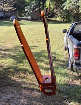
4) The AGCO guy was able to straighten my cultivator lift arms (logging accident or a wreck down a ravine, not sure which). He didn't charge anything which was nice. I had primed most parts on the June trip and just gave a coat of orange (other than the lift arms).
5) I spent one day doing some electrical work in the barn. A little tired of tripping over tangled extension cords.
6) Worked on the hydraulic tank mounts. What I designed needs a minor mod to add a hangover lip to prevent it from slipping off sideways. I decided to add some rubber mounting pads to the tank. Too much metal to metal scuffing. I'll probably glue them to the tank.
7) I investigated whether mods are needed to prevent the PTO shaft from angling too much with the finish mower. As is, the lower lift arm travel is limited to 2 inches below the angle it sits at on flat ground. The limit is how far in the hydraulic cylinders will go. If it needs to be limited further, I could add some non-scuffing collars around the cylinder rods, maybe. I was unable to find a protractor or anything to actually measure an angle, so I ordered one for next trip. I'll consider what happens when the rear end of the mower tilts upward also. The angle is probably not ideal, partly due to the add-on "overrun" clutch, partly due to the "flexible/floating" 3-point top link attachment which may be allowing too much flexibility. At least on one occasion, the PTO shaft pressed against the top link bracket on the mower and gouged the plastic protector.
8) Added a manifold 1/8 port to allow a vacuum reading. After determining that my cheap vacuum meter was not correctly calibrated, I manually "calibrated" it and got good readings of ~22 inches hg. This was confirmed later with a higher quality meter.
Edited by dfwallis - 04 Aug 2025 at 11:54am
|
|
1952 CA13092, CA Pickup Plow, CA Cultivator, CA Two Row Planter, Dunham-Lehr GC78 Disc, Grader Blade, 3pt Fm180 Finish Mower
|
|
DSpears N IL
Silver Level Access


Joined: 11 Sep 2009
Location: Rockford,Ill
Points: 418
|
Post Options
Thanks(0)
Quote Reply
Posted: 04 Aug 2025 at 7:55pm |
can you share some pictures of the canopy mounting to the outside of the fenders? The uprights look to be good for the canopy to hold. Thanks Dewayne
|
|
dfwallis
Orange Level
Joined: 09 Mar 2023
Location: Texas / Indiana
Points: 958
|
Post Options
Thanks(0)
Quote Reply
Posted: 04 Aug 2025 at 8:36pm |
 DSpears N IL wrote: DSpears N IL wrote:
can you share some pictures of the canopy mounting to the outside of the fenders?The uprights look to be good for the canopy to hold. Thanks Dewayne
|
I don't really like what I've done, but there was just not a lot of good options. The supplemental bail mounts to the cultivator bracket position. This gives me pretty good vertical support on the axle (but of course requires the wheels spun out just a bit, which I don't mind because it's a tiny bit more stable). I left a vertical protrusion on purpose while I was deciding whether to add a canopy/ROPS. So the vertical frame supports for the canopy are attached to this vertical protrusion above the cultivator bracket. So as to not further limit how far in I could bring the tires, I mounted the supports on the inside toward the fenders. This then limited the thickness that I had intended to use to gain ROPS strength. The thickness I wanted worked on one side but not the other, perhaps bent fenders (didn't bother to see where it was off). For now, I use clamps (half inch plates with 4 half inch bolts) with a single 3/4 through pin with an R clip. It is rock solid. You can pick the tractor up with it with zero deflection, zero rotation. I used 3/4 x 4 inch flats for ease of fitment. I could easily add some square tubing to the outside of each rail to improve the side to side bending resistance, again at the cost of limits on tire adjustment range. All because i didn't want to mod the platform. I guess I could have bought another platform and modified it like I did for the PTO guard, but then again, there's not many other good locations to bolt onto other than giant clamps around the axle (like the H and M use).
Edit: Those rails are pretty darn heavy. I may not be able to lift them into place in a another few years :(
Edited by dfwallis - 04 Aug 2025 at 8:42pm
|
|
1952 CA13092, CA Pickup Plow, CA Cultivator, CA Two Row Planter, Dunham-Lehr GC78 Disc, Grader Blade, 3pt Fm180 Finish Mower
|
|
dfwallis
Orange Level
Joined: 09 Mar 2023
Location: Texas / Indiana
Points: 958
|
Post Options
Thanks(0)
Quote Reply
Posted: 05 Aug 2025 at 5:05pm |
My original plan was to use 5 x 2 or 5 x 3 rectangular tubing, but I was unable to get it locally (at least quickly). It's still an option for reinforcement.
Edit: I was surprised at how nice and square everything fit together. When I clamped the vertical risers to the cultivator bracket, they met almost perfectly flat and inline with the other side. The reinforced angle brackets mating the side rails to the top were preformed items I bought off the internet. I've used those on the side rails in places also, except those were slotted and these I had to drill. There was almost no distortion caused by tightening all those bolts at the top. Of course it all started with the guy that welded my bail together. I stressed to him how important it was to be perfectly square.
Edited by dfwallis - 06 Aug 2025 at 3:45pm
|
|
1952 CA13092, CA Pickup Plow, CA Cultivator, CA Two Row Planter, Dunham-Lehr GC78 Disc, Grader Blade, 3pt Fm180 Finish Mower
|
|
jvin248
Orange Level

Joined: 17 Jan 2022
Location: Detroit
Points: 505
|
Post Options
Thanks(0)
Quote Reply
Posted: 05 Aug 2025 at 8:42pm |
dfwallis wrote:

|
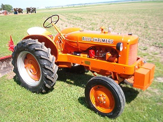
That photo looks like a tractor fresh off the factory assembly line. .
Edited by jvin248 - 05 Aug 2025 at 8:45pm
|
|
dfwallis
Orange Level
Joined: 09 Mar 2023
Location: Texas / Indiana
Points: 958
|
Post Options
Thanks(0)
Quote Reply
Posted: 06 Aug 2025 at 12:04pm |
jvin248 wrote:
dfwallis wrote:
|
That photo looks like a tractor fresh off the factory assembly line.
. |
Believe me, there are plenty of dings, new and old :) And the paint job is substandard. I had great difficulty getting the water out of the compressor feed 400 feet away in the garage... and I'm not really sure how VS can call this paint "super premium".
|
|
1952 CA13092, CA Pickup Plow, CA Cultivator, CA Two Row Planter, Dunham-Lehr GC78 Disc, Grader Blade, 3pt Fm180 Finish Mower
|
|
dfwallis
Orange Level
Joined: 09 Mar 2023
Location: Texas / Indiana
Points: 958
|
Post Options
Thanks(0)
Quote Reply
Posted: 24 Sep 2025 at 12:43pm |
09/24/2025 Status (1):
I'll create separate posts because it's easier to add incrementally.
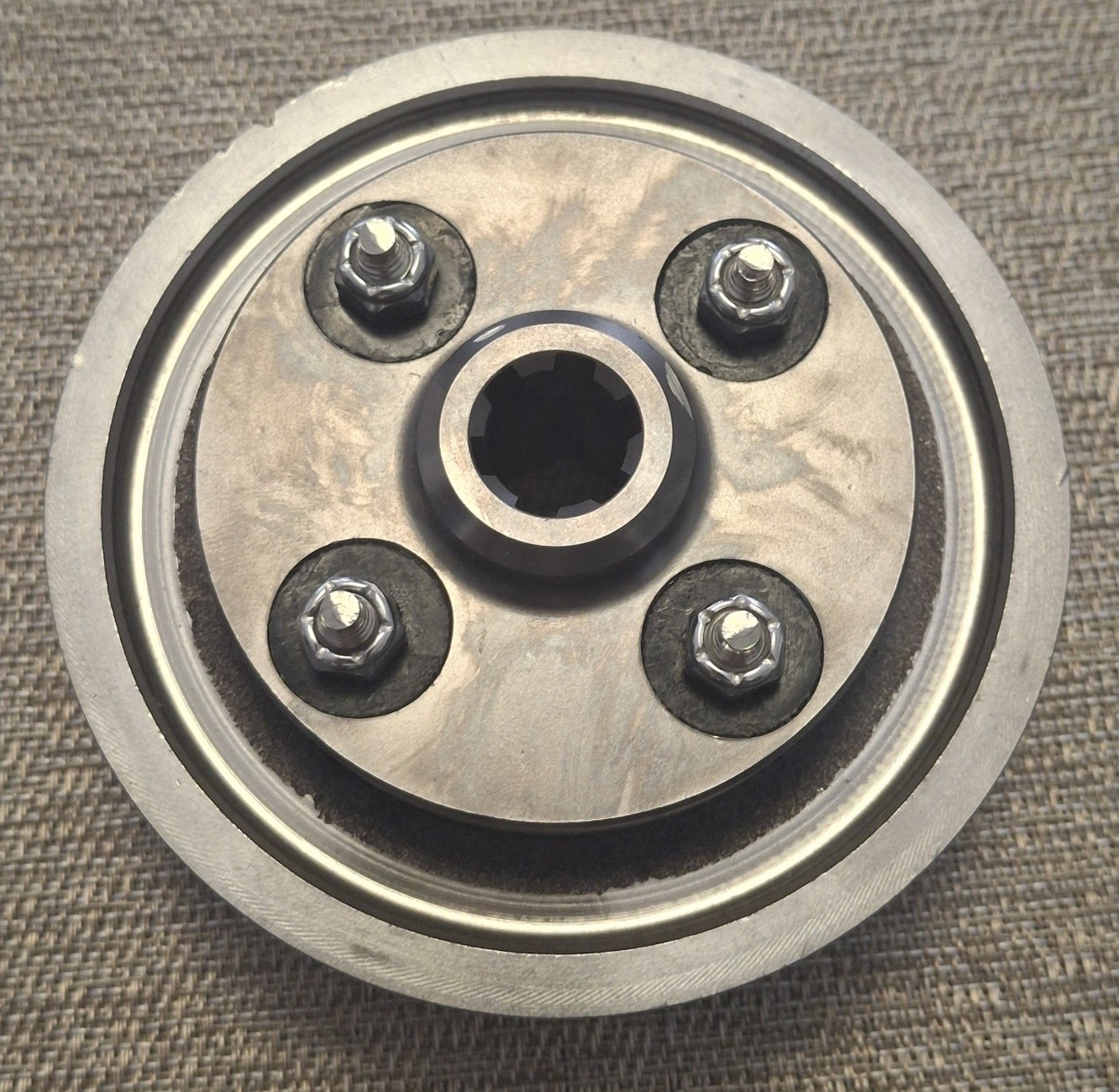
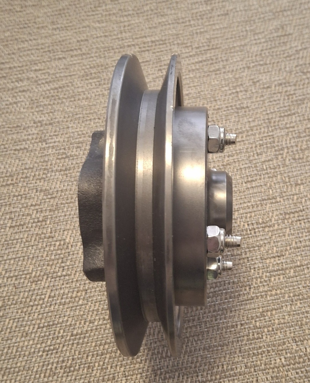
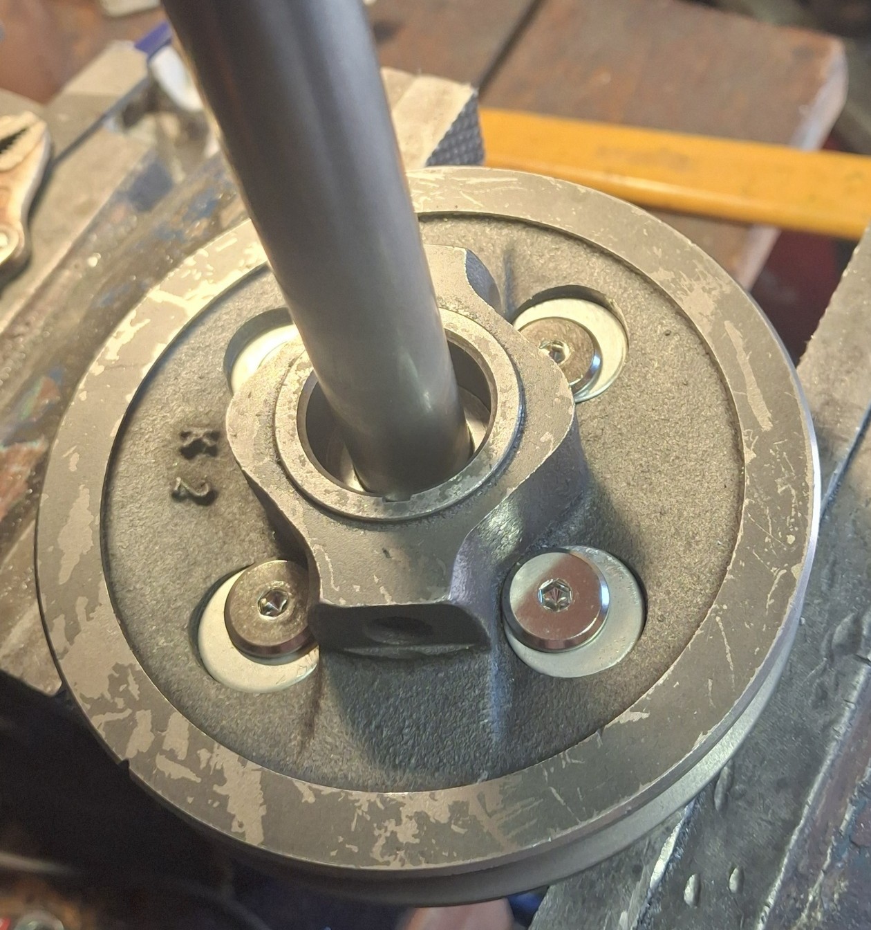
My plan is to make my add-on hydraulic pump support mounting either at the rear belt or on the cultivator bracket on the front. However, the pulley and drive adaptor recommended by Steiner for a CA don't work for me. The recommended item has a 1 inch spline and the maximum spline that will go through the crank hole is 13/16" (wanting it to be removable without difficulty). So I bought the adapter for the 3/4 spline recommended for a Ford and adapted it to fit to the CA recommended pulley. I would have rather drilled the spline adapter, but it was so hard, even the hardest drill bits (and punches) would not even put a dent in it. I could barely scratch it with an awl. I drilled the pulley mounting holes out to 5/8 and the bolts fit neatly against the sides. I created some special off-sided washers to ensure a nice even surface to tighten against. I used the 13+ inch spline rod so that it protrudes beyond the cultivator bracket. I used an insert to ensure that the spline adapter was properly centered on the pulley. Since it fits with little movement possible, it was already well centered. It will be attached with a rubber drive coupler. I wanted to use a U-drive but they were too bulky.
|
|
1952 CA13092, CA Pickup Plow, CA Cultivator, CA Two Row Planter, Dunham-Lehr GC78 Disc, Grader Blade, 3pt Fm180 Finish Mower
|
|
dfwallis
Orange Level
Joined: 09 Mar 2023
Location: Texas / Indiana
Points: 958
|
Post Options
Thanks(0)
Quote Reply
Posted: 24 Sep 2025 at 12:55pm |
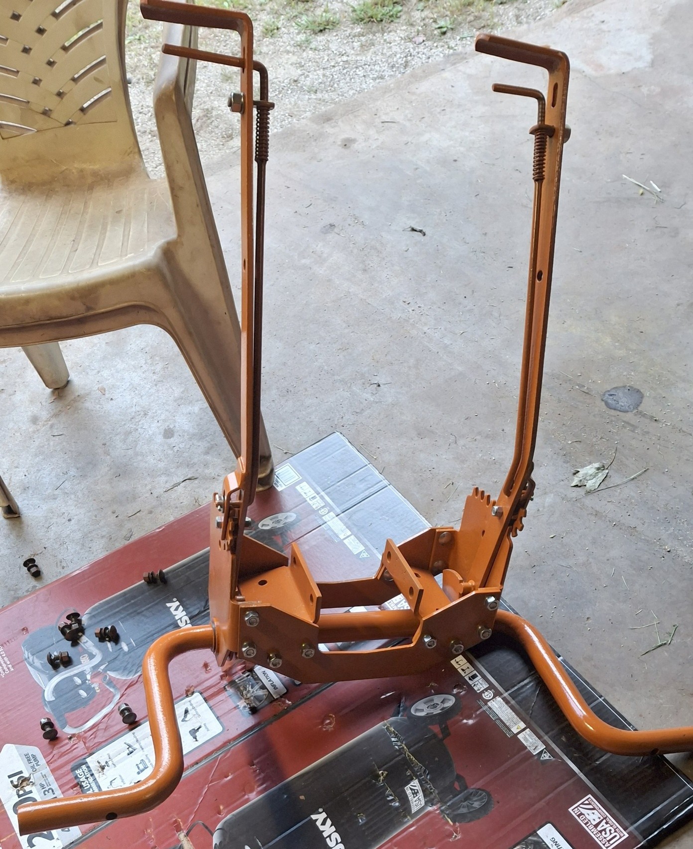
09/24/2025 Status (2):
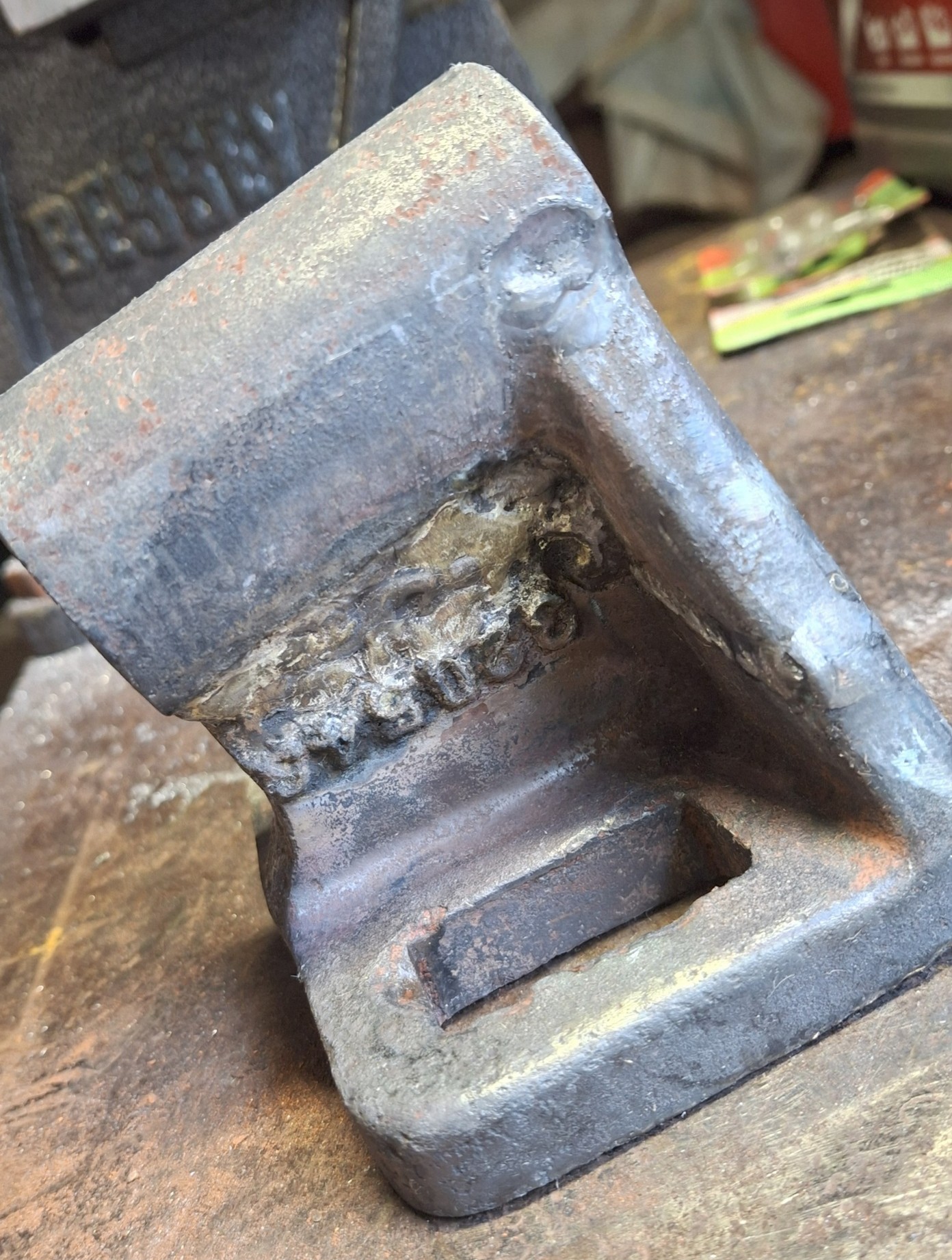
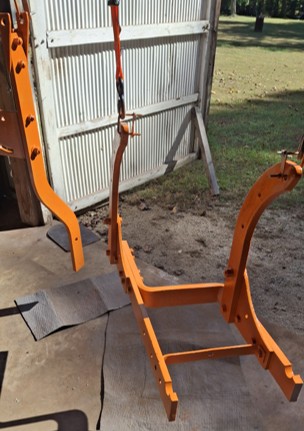
In August I cleaned and painted various cultivator parts that mount directly to the tractor. In early September I assembled the lift arm section that mounts to the torque tube and the front toolbar. I also retrieved the broken toolbar mount bracket from its grave and had it welded.
Edited by dfwallis - 24 Sep 2025 at 2:43pm
|
|
1952 CA13092, CA Pickup Plow, CA Cultivator, CA Two Row Planter, Dunham-Lehr GC78 Disc, Grader Blade, 3pt Fm180 Finish Mower
|
|
dfwallis
Orange Level
Joined: 09 Mar 2023
Location: Texas / Indiana
Points: 958
|
Post Options
Thanks(0)
Quote Reply
Posted: 24 Sep 2025 at 1:00pm |
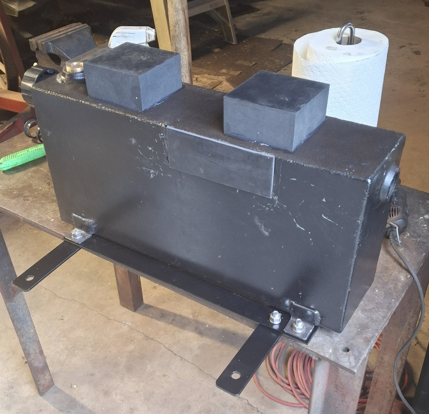
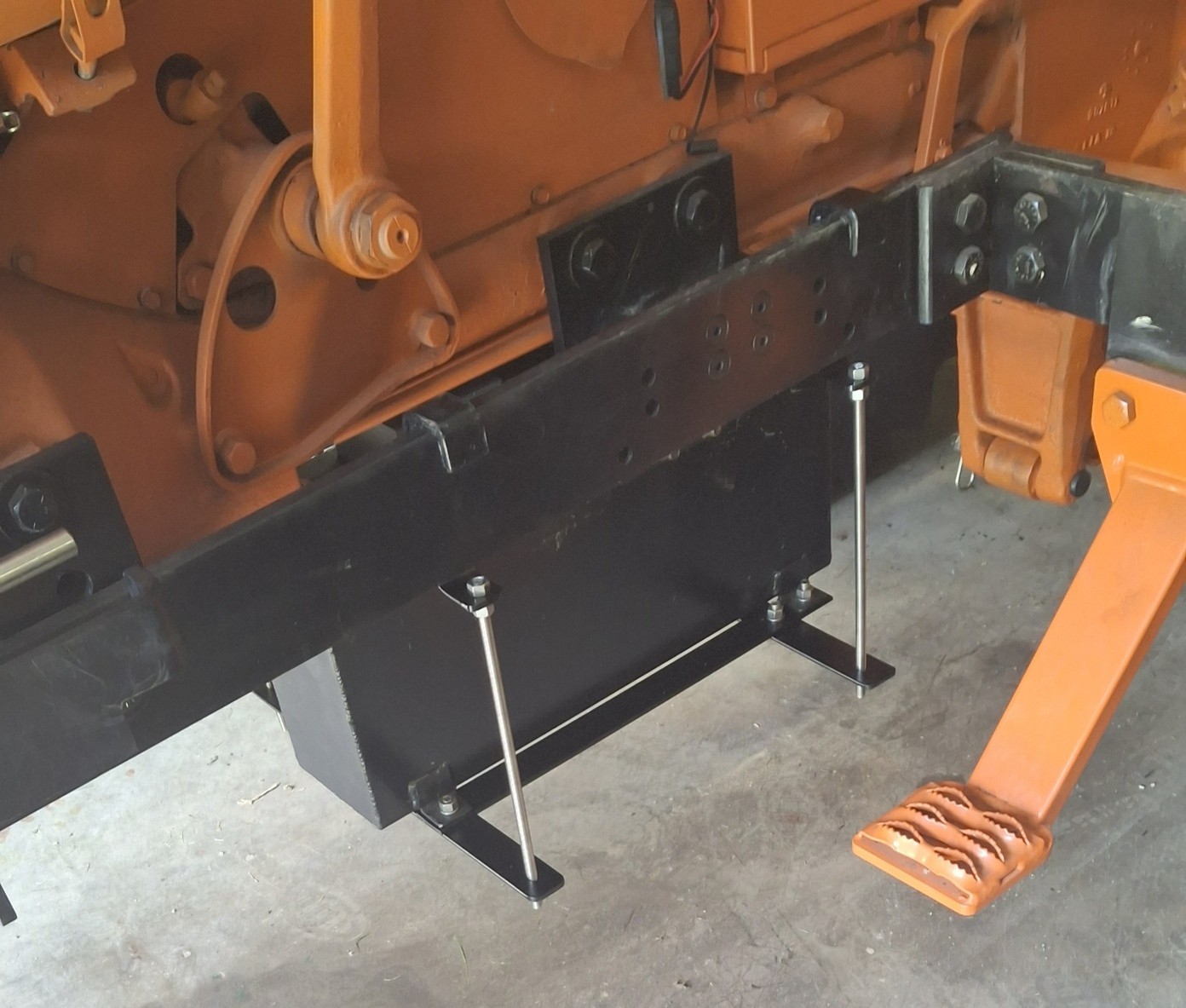
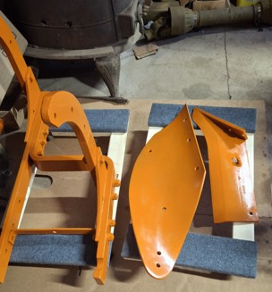
09/24/2025 Status (3):
I finished up the hydraulic tank mounting brackets (redesigned to have a lip/hook at the top to prevent slipping off). I also added rubber mounting pads to tighten against and restrict movement when mounted.
The tank was custom designed to fit in this space by a Chicago company. It is a 5 gallon tank.
Edited by dfwallis - 24 Sep 2025 at 2:27pm
|
|
1952 CA13092, CA Pickup Plow, CA Cultivator, CA Two Row Planter, Dunham-Lehr GC78 Disc, Grader Blade, 3pt Fm180 Finish Mower
|
|
dfwallis
Orange Level
Joined: 09 Mar 2023
Location: Texas / Indiana
Points: 958
|
Post Options
Thanks(0)
Quote Reply
Posted: 24 Sep 2025 at 1:07pm |
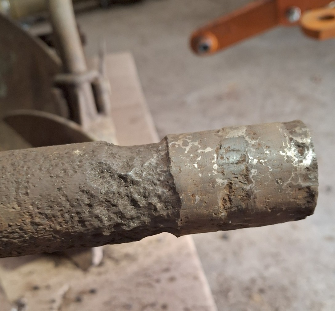
09/24/2025 Status (4):
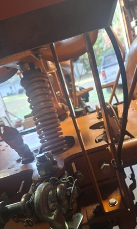
The plow main lift rod was severely pitted (but still fully functional). For cosmetic reasons, I had it weld filled. It turned out ok. I may patch those weld pit artifacts to reduce corrosion potential at some point.
|
|
1952 CA13092, CA Pickup Plow, CA Cultivator, CA Two Row Planter, Dunham-Lehr GC78 Disc, Grader Blade, 3pt Fm180 Finish Mower
|
|
dfwallis
Orange Level
Joined: 09 Mar 2023
Location: Texas / Indiana
Points: 958
|
Post Options
Thanks(0)
Quote Reply
Posted: 24 Sep 2025 at 1:26pm |
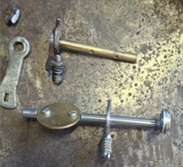
09/24/2025 Status (5):
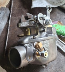
As a continuation of my carburetor performance trials and tribulations, I was able to acquire a rebuilt TSX670. I had read here that it was compatible, but it isn't without significant modification. Additionally, it has a 3/4 inch venturi versus the 5/8 inch venturi of the TSX486. After modification, the tractor idles without misfiring about as well as with the Zenith 12566, but it still misfires at higher RPMs. The 12566 at certain mod stages did not misfire at all at higher RPMs but the tractor would die if there was any sudden RPM or load change. You had to gradually increase RPMs to keep it running. The tractor is fully functional again and I've received the TSX486 in TX (after getting lost in USPS for 2 weeks). I'll continue working on it to see if I can identify any issues. I'll not repeat the rest of the other thread here.
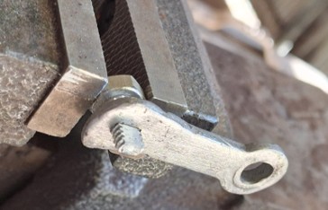
I reused the old parts that came from the TSX486 before I installed the rebuild kit. This throttle rod/lever was a mangled welded mess with the control rod section not fully clamped to the upper arm so it had about 1/4 inch of slop in its rotation. Anyway, I dremeled it apart and reshaped it with the grinder to make usable parts. That part at the top left is part of the glob of weld material. The 670 would not mount because the throttle rod was too long and hit the block. The throttle plate of the 670 is also larger than the 486 so I had to widen the mounting position on the brass rod and then had to very slightly trim the edge of the plate so that it would close sufficiently to achieve idle RPM.
In order to make the upper arm position adjustable, I created a lock bolt/nut configuration similar to that used on the Zenith.
After completion the arm was still too close to the block, so I had to kink the arm about 1/4 inch out.
Edited by dfwallis - 25 Sep 2025 at 11:01am
|
|
1952 CA13092, CA Pickup Plow, CA Cultivator, CA Two Row Planter, Dunham-Lehr GC78 Disc, Grader Blade, 3pt Fm180 Finish Mower
|
|
dfwallis
Orange Level
Joined: 09 Mar 2023
Location: Texas / Indiana
Points: 958
|
Post Options
Thanks(0)
Quote Reply
Posted: 24 Sep 2025 at 1:51pm |
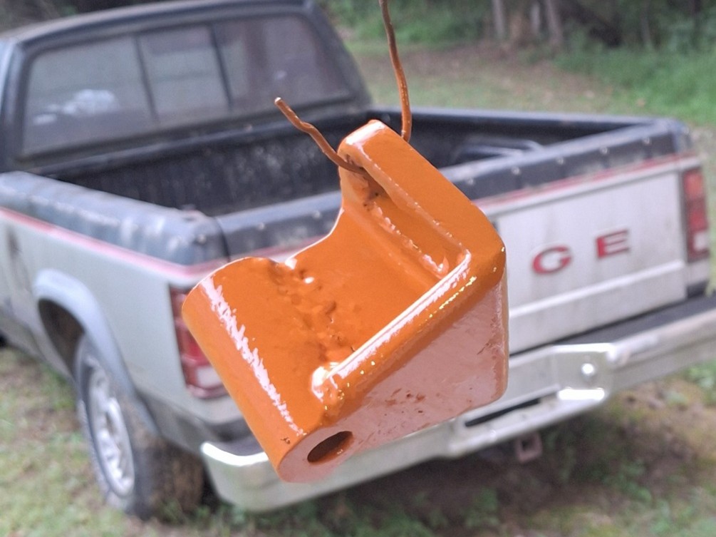
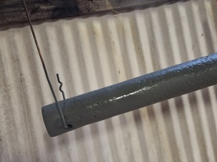
09/24/2025 Status (6):
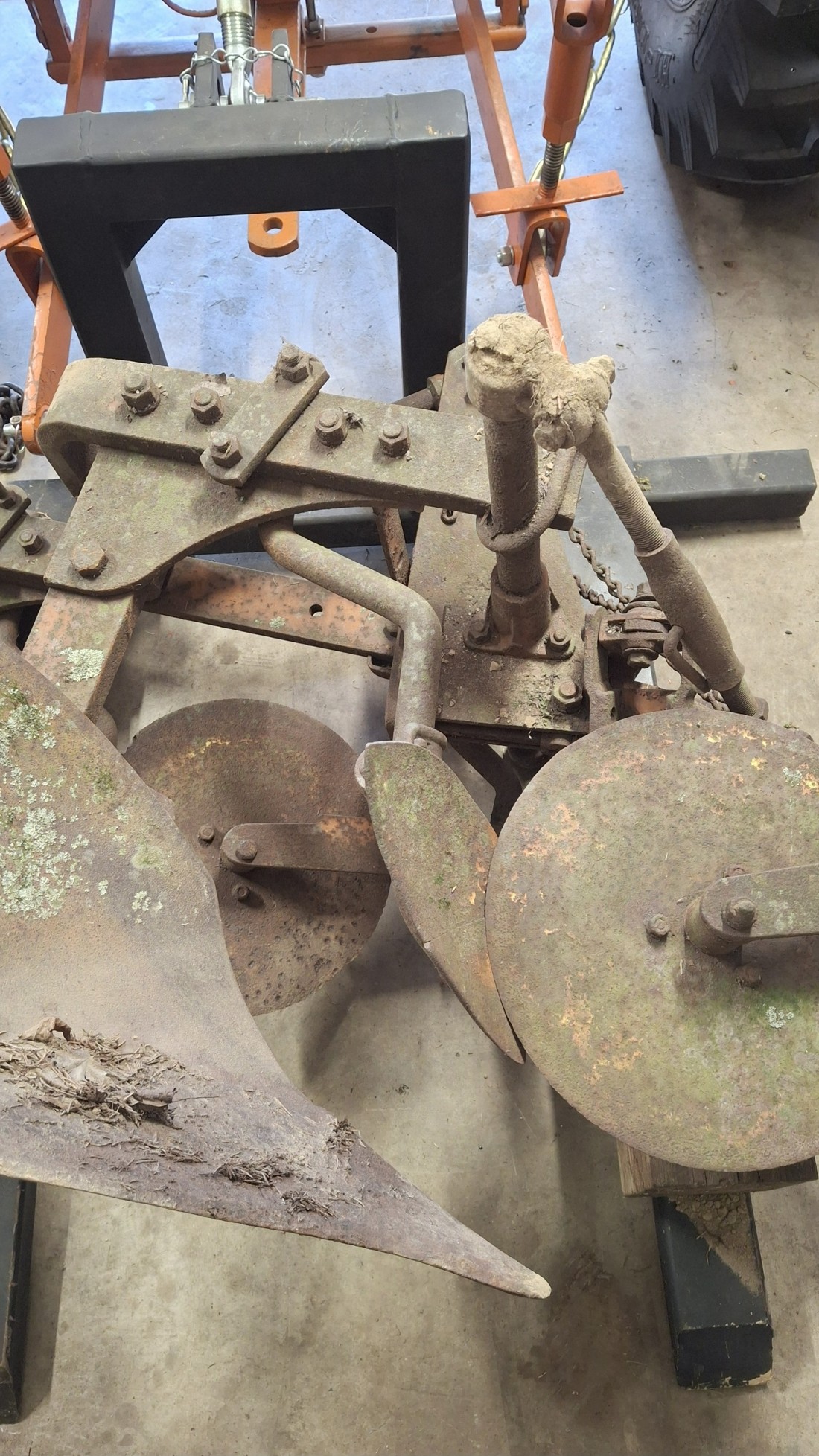
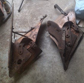
I switched to working on the 2-14 "pickup" plow (325). I used my new 3pt forks to pick it up from its grave.
I began dismantling. Most bolts came lose with the impact driver (and lots of soaking in PB Blaster), but some of the plow bottom bolts had to be cut off. There was nothing left of the nuts or the square portion of the heads. Some of the plow bolts were a little difficult to get tools to. But I didn't damage or break anything at least. I'll probably reassemble with strategically placed stainless bolts. I don't plan to take the frame itself apart. There's no real need. I'll just sand blast the bolts and give it a good cleaning.
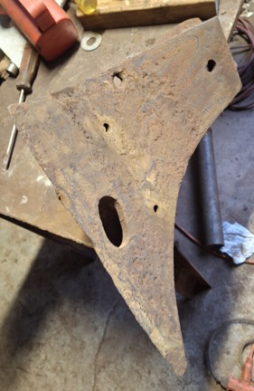
Example of the crud removed. This is actually a coating of dirt that has embedded rust particles that make it hard as a rock. I used an angle grinder, angle sander, dremel, wire brush, and sand blaster to get this cleaned up. Didn't look too bad in the end.
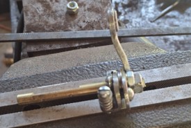
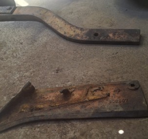
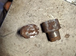
I also had to straighten one of those turnbuckle bolts (welder heated it). I don't know how you can bend a turnbuckle bolt while doing absolutely no damage to the turnbuckle its screwed into. Also straightened the crank handle and made a new pin. The old pin was worn plus the hole was wallowed out. I used a roll pin instead of a solid pin.
Edited by dfwallis - 25 Sep 2025 at 11:05am
|
|
1952 CA13092, CA Pickup Plow, CA Cultivator, CA Two Row Planter, Dunham-Lehr GC78 Disc, Grader Blade, 3pt Fm180 Finish Mower
|
|
dfwallis
Orange Level
Joined: 09 Mar 2023
Location: Texas / Indiana
Points: 958
|
Post Options
Thanks(0)
Quote Reply
Posted: 24 Sep 2025 at 2:08pm |
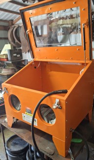
09/24/2025 Status (7):
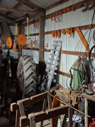
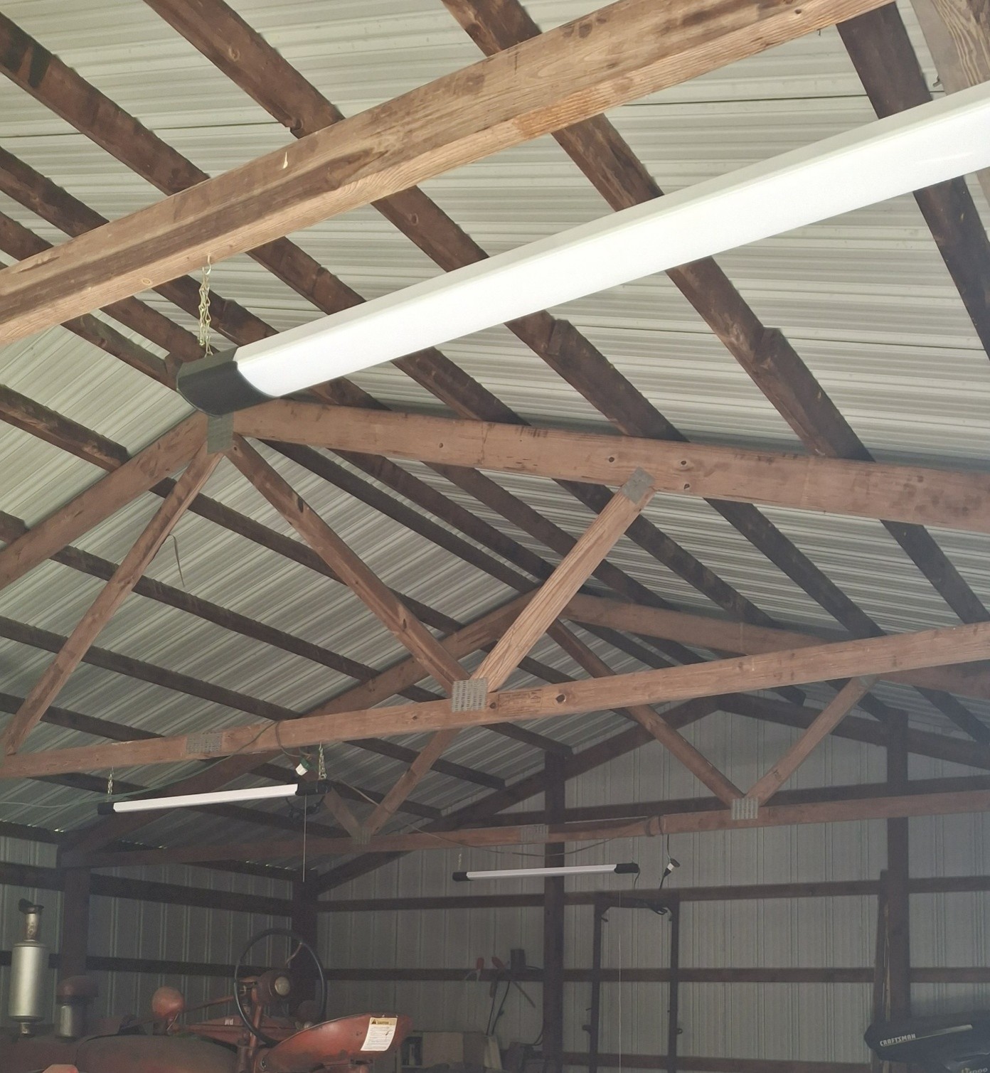
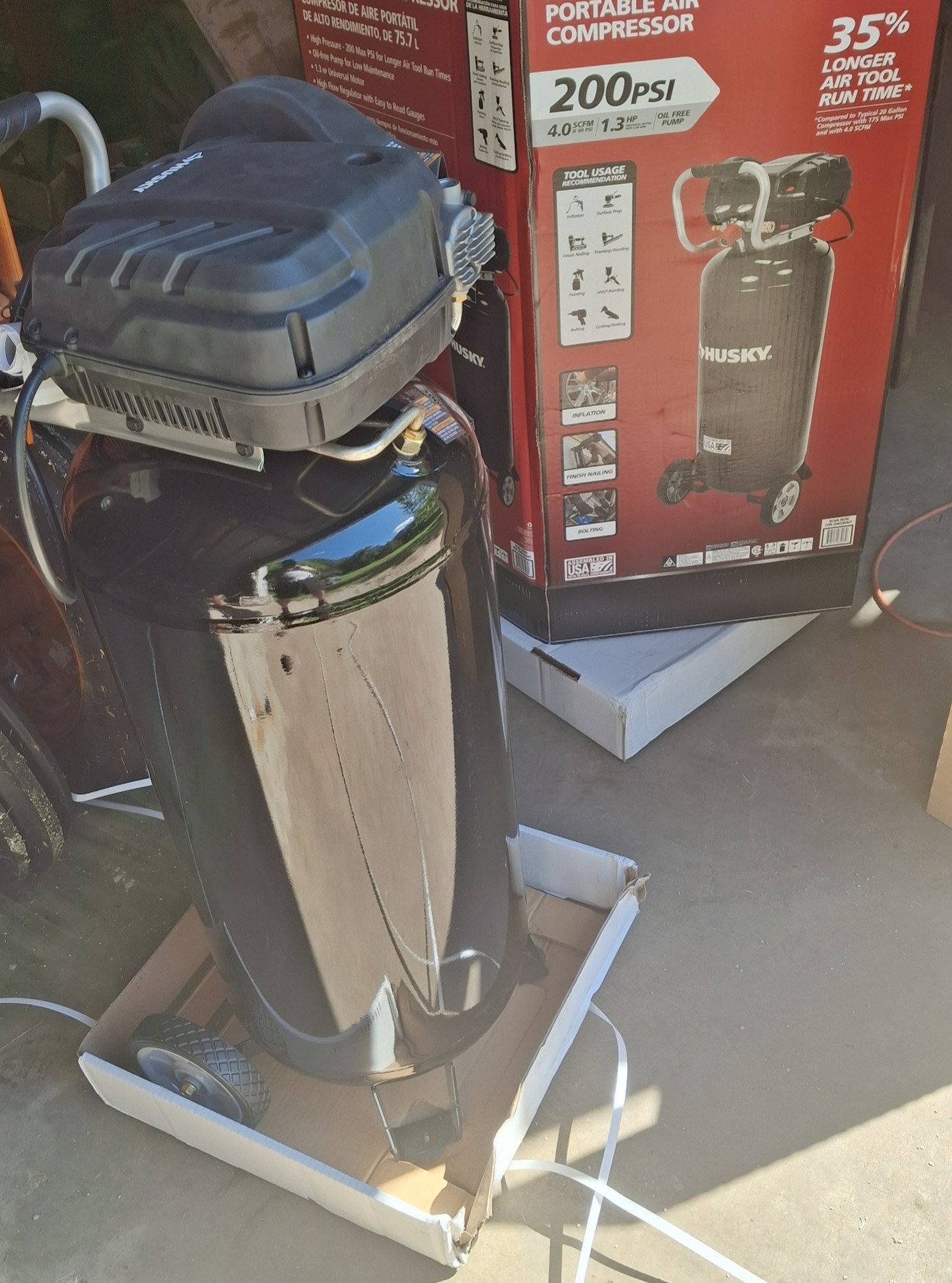
To improve my work environment a little, I finished up the wiring for some more light fixtures and outlets and added a compressor and a sandblast cabinet. The sandblast cabinet will save a huge amount on media. However, the compressor is only 4 cfm. The electrical circuit to the barn is unable to handle much more than about 1000 watts. When its running, the dremel slows to a crawl. It is possible that I ran both legs of the 220 from the pump house into the barn (25 years ago), though. I see another coiled section of wire that's unused. So I may be able to give the compressor it's own circuit (to be investigated next trip). That would also allow me to connect the sandblast cabinet exhaust fan at the same time (although it draws a little more current than I expected). As-is, the cabinet is a little difficult to use without dust collection. If I can't do that, I may get a cordless vacuum if I can find one with enough throughput. I generally only sandblast hard to reach areas and severe rust pits and weld joints because I don't have enough cfm. I could also connect the big compressor as I've been doing. It's 400 feet away in the garage but is a pain to set up. There's no electrical service in the garage and I have to connect a long extension to the dryer circuit in the house, then a 400 foot hose to the barn... 
This pic is before I finished the wiring. The additional fixtures were plugged into extension cords which have now been eliminated. The 4 central fixtures are on a switched circuit and each individually pull cord operated to make it easy to turn off unneeded lights. Fixtures over the workbench and the drill press are plugged into outlets.
Edited by dfwallis - 26 Sep 2025 at 3:56pm
|
|
1952 CA13092, CA Pickup Plow, CA Cultivator, CA Two Row Planter, Dunham-Lehr GC78 Disc, Grader Blade, 3pt Fm180 Finish Mower
|
|
dfwallis
Orange Level
Joined: 09 Mar 2023
Location: Texas / Indiana
Points: 958
|
Post Options
Thanks(0)
Quote Reply
Posted: 24 Sep 2025 at 2:48pm |
|
09/24/2025 Status (8): I also investigated changes to make to my tachometer design. After finding a convenient scope probe circuit that preconditions the high voltage secondary signal to a low level signal, I've decided to investigate using that circuit rather than my belly mounted flywheel sensor. It will require additional signal conditioning though since the polarity is reversed. I think I can solve that fairly simply.
|
|
1952 CA13092, CA Pickup Plow, CA Cultivator, CA Two Row Planter, Dunham-Lehr GC78 Disc, Grader Blade, 3pt Fm180 Finish Mower
|
|
steve(ill)
Orange Level Access
Joined: 11 Sep 2009
Location: illinois
Points: 91060
|
Post Options
Thanks(0)
Quote Reply
Posted: 24 Sep 2025 at 10:38pm |
|
Gary, sounds like long term you need MORE POWER to the shed... 1000 watts on 120v is only 8 amps... Dont know what size wire you ran out there ... probably just a 14 or 12 gauge Romex ?? Sounds like you need to put in a 8 gauge 220v like from the dryer supply ? 30 or 40 amps would give you a LOT of room for several items / equip.
|
|
Like them all, but love the "B"s.
|
|
Sugarmaker
Orange Level
Joined: 12 Jul 2013
Location: Albion PA
Points: 8662
|
Post Options
Thanks(0)
Quote Reply
Posted: 25 Sep 2025 at 6:46am |
dfwallis, You might think about setting up a Electrolysis tank to assist in cleaning some of your plow parts. Regards, Chris and Cheryl
|
|
D17 1958 (NFE), WD45 1954 (NFE), WD 1952 (NFE), WD 1950 (WFE), Allis F-40 forklift, Allis CA, Allis D14, Ford Jubilee, Many IH Cub Cadets, 32 Ford Dump, 65 Comet, 66 F100.
|
|
CA13414
Silver Level

Joined: 25 Feb 2024
Location: Nebraska
Points: 397
|
Post Options
Thanks(0)
Quote Reply
Posted: 25 Sep 2025 at 7:12am |
|
Awesome progress. It is fun to watch it come together.
Love all your creative ideas.
Dan
|
|
Helping the aged survive and thrive! 1953 CA
|
|
dfwallis
Orange Level
Joined: 09 Mar 2023
Location: Texas / Indiana
Points: 958
|
Post Options
Thanks(0)
Quote Reply
Posted: 25 Sep 2025 at 9:28am |
steve(ill) wrote:
Gary, sounds like long term you need MORE POWER to the shed... 1000 watts on 120v is only 8 amps... Dont know what size wire you ran out there ... probably just a 14 or 12 gauge Romex ?? Sounds like you need to put in a 8 gauge 220v like from the dryer supply ? 30 or 40 amps would give you a LOT of room for several items / equip. |
The pump house is fairly close to the barn. The main problem is the 220v buried wiring to the pump house is undersized. Dad investigated what it would take to wire the barn but the REMC said it was too far and he would need to set new poles (probably at least 2 ($$$$)). He didn't want me to run wiring from the pump house, but I didn't like running a drop cord from the pump house in the ice and snow to the barn to run the drill press and welder and flickering florescent lighting. He rebuilt multiple model Ts, Thunderbirds, tractors that way. The 12 gauge romex was intended for outlets and lighting inside the barn. It's been sitting there waiting to be used for about 25 years. One day...
|
|
1952 CA13092, CA Pickup Plow, CA Cultivator, CA Two Row Planter, Dunham-Lehr GC78 Disc, Grader Blade, 3pt Fm180 Finish Mower
|
|
dfwallis
Orange Level
Joined: 09 Mar 2023
Location: Texas / Indiana
Points: 958
|
Post Options
Thanks(1)
Quote Reply
Posted: 25 Sep 2025 at 9:29am |
CA13414 wrote:
Awesome progress. It is fun to watch it come together.
Love all your creative ideas.
Dan |
A guy can accomplish a lot with stone knives and bear skins (inadequate tools) :)
|
|
1952 CA13092, CA Pickup Plow, CA Cultivator, CA Two Row Planter, Dunham-Lehr GC78 Disc, Grader Blade, 3pt Fm180 Finish Mower
|
|
dfwallis
Orange Level
Joined: 09 Mar 2023
Location: Texas / Indiana
Points: 958
|
Post Options
Thanks(0)
Quote Reply
Posted: 25 Sep 2025 at 9:30am |
Sugarmaker wrote:
dfwallis,You might think about setting up a Electrolysis tank to assist in cleaning some of your plow parts. Regards, Chris and Cheryl |
I've done that before. I may try it out again. I'm almost completely done with the plow, aside from the frame itself. The Dunham Lehr (GC78, 7'4") disc is next, but I don't think I'll do much with that before next spring. Maybe get the rims/tires in shape (or replaced). Take the crank handle to get straightened.
Edited by dfwallis - 25 Sep 2025 at 11:10am
|
|
1952 CA13092, CA Pickup Plow, CA Cultivator, CA Two Row Planter, Dunham-Lehr GC78 Disc, Grader Blade, 3pt Fm180 Finish Mower
|
|
dfwallis
Orange Level
Joined: 09 Mar 2023
Location: Texas / Indiana
Points: 958
|
Post Options
Thanks(0)
Quote Reply
Posted: 26 Sep 2025 at 5:17pm |
dfwallis wrote:
09/24/2025 Status (8): I also investigated changes to make to my tachometer design. After finding a convenient scope probe circuit that preconditions the high voltage secondary signal to a low level signal, I've decided to investigate using that circuit rather than my belly mounted flywheel sensor. It will require additional signal conditioning though since the polarity is reversed. I think I can solve that fairly simply. |
Unfortunately, the scope probe I chose attenuates the signal down to a ridiculous 0.2 volts which makes it a bit difficult to create a passive conditioning circuit (Schottky diodes are sort of working, but not symmetrically) . One website says it's a 1000 to 1 attenuation...another says 10000 to 1. 10000 to 1 is correct.
It's also capacitive and complicates connecting to "ground" in a positive ground system while also conditioning the output. The conditioning circuit is also highly susceptible to EMI because the signal level is so low in comparison to the noise.
But I've identified a better probe solution that is inductive which makes it easy to simply reverse the isolated connection leads (positive ground to negative ground). The output will be a 10-20vdc pre-conditioned "trigger" pulse. All I'll need to do is attenuate for the Arduino input level (hopefully).
|
|
1952 CA13092, CA Pickup Plow, CA Cultivator, CA Two Row Planter, Dunham-Lehr GC78 Disc, Grader Blade, 3pt Fm180 Finish Mower
|
|
dfwallis
Orange Level
Joined: 09 Mar 2023
Location: Texas / Indiana
Points: 958
|
Post Options
Thanks(0)
Quote Reply
Posted: 20 Oct 2025 at 7:49pm |
|
I started working on the Dunham Lehr gc78 disc. It appears that the disc was originally painted ac orange 1. No evidence of any other color. Apparently they painted whatever was wanted. Edit: The hydraulic cylinder does appear to be flambeau red. It's the only thing with any paint left. I only see orange in spots after cleaning grime off.
Edited by dfwallis - 21 Oct 2025 at 7:41pm
|
|
1952 CA13092, CA Pickup Plow, CA Cultivator, CA Two Row Planter, Dunham-Lehr GC78 Disc, Grader Blade, 3pt Fm180 Finish Mower
|
|
dfwallis
Orange Level
Joined: 09 Mar 2023
Location: Texas / Indiana
Points: 958
|
Post Options
Thanks(0)
Quote Reply
Posted: 26 Oct 2025 at 2:22pm |
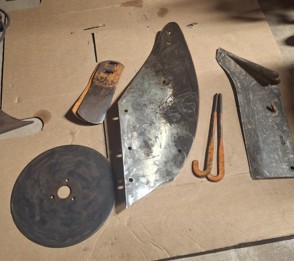
10/26/2025 Status (1): I was able to acquire all of the plow parts I needed with the exception of two bolts.
The plow share is an 801 (soft centered steel) rather than an 807 (chilled iron). If I ever find an 807, I'll probably go ahead and get it. The MB extensions are not quite like the originals which have squared off ends with round corners, but I received two so will match. The PS was painted a cream color. I don't think that would be the case for a 1952 (if anyone knows otherwise, let me know). I did some minor sand blasting on these before painting.
|
|
1952 CA13092, CA Pickup Plow, CA Cultivator, CA Two Row Planter, Dunham-Lehr GC78 Disc, Grader Blade, 3pt Fm180 Finish Mower
|
|
dfwallis
Orange Level
Joined: 09 Mar 2023
Location: Texas / Indiana
Points: 958
|
Post Options
Thanks(0)
Quote Reply
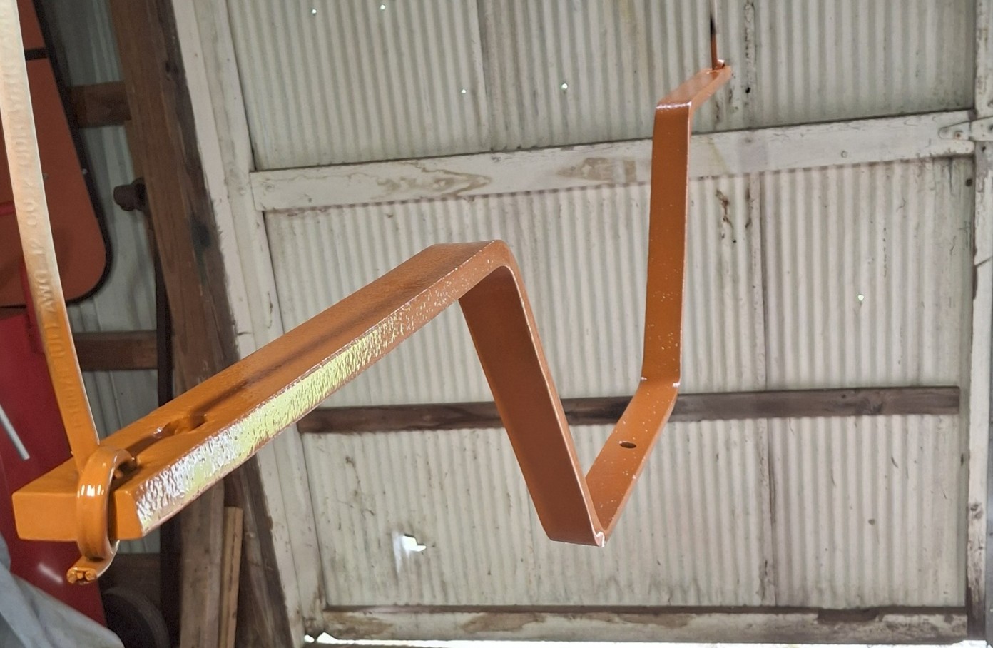
Posted: 26 Oct 2025 at 2:29pm |
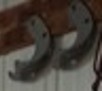
10/26/2025 Status (2): I didn't get very far assembling the plow parts because the paint was drying so slow. It was down in the 30s a few nights, although it usually warmed into the 60s and 70s fairly quickly in the morning. I had also forgotten that I didn't finish these curved brackets because they were severely bent and I had to determine how they needed to be straightened. After a few days of drying they were still super sticky so I opted to switch to other things (generator/regulator, sandblast cabinet cart/setup, barn cleanup, Dunham Lehr disc).
|
|
1952 CA13092, CA Pickup Plow, CA Cultivator, CA Two Row Planter, Dunham-Lehr GC78 Disc, Grader Blade, 3pt Fm180 Finish Mower
|
|
dfwallis
Orange Level
Joined: 09 Mar 2023
Location: Texas / Indiana
Points: 958
|
Post Options
Thanks(0)
Quote Reply
Posted: 26 Oct 2025 at 2:40pm |
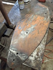
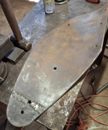
10/26/2025 Status (3): The largest part of the trip was spent cleaning and painting the plow frame. There were a few areas that were severely pitted that I filled with weld material with epoxy in the pinholes. I didn't spend a huge amount of time on that but it came out looking pretty decent and much of the weld areas will be covered by various brackets anyway. I wanted something more solid and level for the brackets to sit against.
The pressure sandblast pot developed some severe leaks around the filler welds so I bought another siphon gun and siphoned directly from the media bag. It actually worked pretty good. I dropped the pressure pot off at a welder at the same time as I dropped the disc tongue crank. I mostly sandblasted the heavily pitted areas and the bolts that I didn't remove/replace.
Edited by dfwallis - 26 Oct 2025 at 3:28pm
|
|
1952 CA13092, CA Pickup Plow, CA Cultivator, CA Two Row Planter, Dunham-Lehr GC78 Disc, Grader Blade, 3pt Fm180 Finish Mower
|
|
dfwallis
Orange Level
Joined: 09 Mar 2023
Location: Texas / Indiana
Points: 958
|
Post Options
Thanks(0)
Quote Reply
Posted: 26 Oct 2025 at 2:47pm |
|
10/26/2025 Status (4): No pictures, but I also took the generator/regulator to the shop for testing. I could force it to come on but it never seemed to come on on it's own. I'm pretty sure that's just an adjustment issue, but the shop didn't like the make of the regulator and went ahead and ordered a US-made regulator. It seems to be working correctly now (finally).
|
|
1952 CA13092, CA Pickup Plow, CA Cultivator, CA Two Row Planter, Dunham-Lehr GC78 Disc, Grader Blade, 3pt Fm180 Finish Mower
|
|
dfwallis
Orange Level
Joined: 09 Mar 2023
Location: Texas / Indiana
Points: 958
|
Post Options
Thanks(0)
Quote Reply
Posted: 26 Oct 2025 at 2:53pm |
10/26/2025 Status (5): The SMV bracket I made proved to be just a little too flexible. I used 3/16 flats. So I doubled up and added a second brace section to stiffen it up a bit. I think its good enough now. I had intended to make a diagonal brace, but the 3pt top link bracket would hit it in the "best" positions for it (the vertical rise about 2 inches to the left of the original vertical section). Flexing is now mostly from the 1/4" plate it's mounted to (I can strengthen that if needed).
|
|
1952 CA13092, CA Pickup Plow, CA Cultivator, CA Two Row Planter, Dunham-Lehr GC78 Disc, Grader Blade, 3pt Fm180 Finish Mower
|
|
dfwallis
Orange Level
Joined: 09 Mar 2023
Location: Texas / Indiana
Points: 958
|
Post Options
Thanks(0)
Quote Reply
Posted: 26 Oct 2025 at 3:02pm |
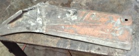
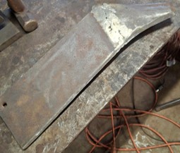
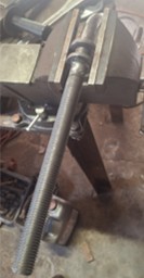
10/26/2025 Status (6): While waiting for plow paint to dry, I switched to some work on the Dunham Lehr disc. First thing was to free the nut from the tongue crank. That wasn't too easy, it was rusted on there pretty good. The threads below it were in really bad shape so rather than try to walk it across those, I cut it off just below the nut. It took a 24 inch pipe wrench and a 5 foot pipe and lots of PB Blaster to slowly walk it off (back and forth). There was little left to the threads outside of where the nut was at. Would not have been worth trying to clean up the threads, so I ordered a B7 grade (1-8) threaded rod and had it welded in.
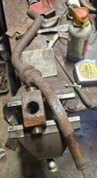
I think it turned out pretty good. Without this, the tongue kind of just flops around. The actual end section that connects to the tractor (converts horizontal to vertical) is completely missing (I think it's just a U shaped piece). It might be somewhere in the barn. I'll look for it later. I did buy a nice trailer ball hitch that will work perfectly (but be a few inches longer).
I also removed and cleaned up the tongue section that the crank mounts to, but I'll need to get those two pieces straightened. I wanted to take all the parts needing straightened at once but I needed to order some 4-point torque sockets to get some parts off. I can't get wrenches on many of the square head bolts for various clearance reasons. The only other parts I've identified so far are the two rear square tubing sections that the rear gangs mount to. The very ends of them are twisted. I think I can easily replace those if they don't suit me. They are actually two sections of angle iron welded to form a square. The disc brochure for a Ground Chief (78) indicates that they switched out this practice so this disc may be a slightly older version of the disc.
Edited by dfwallis - 26 Oct 2025 at 3:24pm
|
|
1952 CA13092, CA Pickup Plow, CA Cultivator, CA Two Row Planter, Dunham-Lehr GC78 Disc, Grader Blade, 3pt Fm180 Finish Mower
|
|