| Author |
 Topic Search Topic Search  Topic Options Topic Options
|
dfwallis 
Orange Level

Joined: 09 Mar 2023
Location: DFW
Points: 925
|
 Post Options Post Options
") Thanks(0) Thanks(0)
 Quote Quote  Reply Reply
 Posted: 18 Mar 2023 at 9:29pm Posted: 18 Mar 2023 at 9:29pm |
") steve(ill) wrote: steve(ill) wrote:
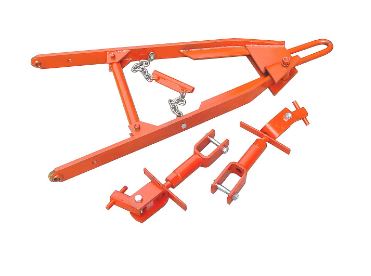
there are basically two different types of AFTERMARKET 3 points you can buy... This one you must remove your drawbar from the snap coupler ( or pin hitch)... and install this in its place ... The two arms are adjustable on width and one is pinned and swings outward. .......... this is made for the snap coupler, but could be MODIFIED to the pin hitch.
|
OK Tractor has this one with an option premade for non-snap-coupler (that I missed before). Like I said, didn't like the design of it, but when time comes I might choose the easy out.
|
 |
|
Sponsored Links
|
|
|
steve(ill)
Orange Level Access
Joined: 11 Sep 2009
Location: illinois
Points: 90498
|
Post Options
Thanks(0)
Quote Reply
Posted: 18 Mar 2023 at 9:35pm |
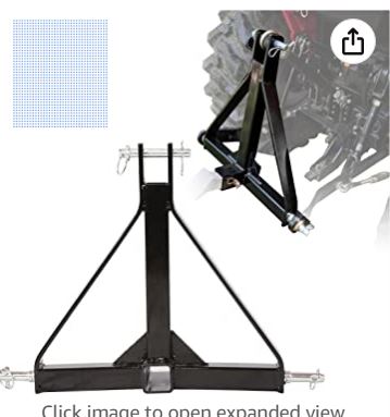
that one eliminates the drawbar... if 90% of your work is with the 3 point, then you can buy an adaptor that gives you the ability to use a drawbar , ball hitch, etc.
|
|
Like them all, but love the "B"s.
|
|
dfwallis
Orange Level
Joined: 09 Mar 2023
Location: DFW
Points: 925
|
Post Options
Thanks(0)
Quote Reply
Posted: 19 Mar 2023 at 10:48am |
dfwallis wrote:
steve(ill) wrote:
there are basically two different types of AFTERMARKET 3 points you can buy... This one you must remove your drawbar from the snap coupler ( or pin hitch)... and install this in its place ... The two arms are adjustable on width and one is pinned and swings outward. .......... this is made for the snap coupler, but could be MODIFIED to the pin hitch.
|
OK Tractor has this one with an option premade for non-snap-coupler (that I missed before). Like I said, didn't like the design of it, but when time comes I might choose the easy out. |
I'll add that OK Tractor seems to have this one for about half the price of Steiner...
|
|
JimD
Orange Level
Joined: 11 Sep 2009
Location: Mounds, OK
Points: 2116
|
Post Options
Thanks(0)
Quote Reply
Posted: 21 Mar 2023 at 11:58pm |
|
Yes, we are significantly less than steiner on most parts. I was just at the factory a week ago. Ill be happy to answer any additional questions.
|
Owner of OKtractor.com PM for an instant response on parts. Open M-F 9-6 Central. We have new and used parts. 877-378-6543
|
|
dfwallis
Orange Level
Joined: 09 Mar 2023
Location: DFW
Points: 925
|
Post Options
Thanks(0)
Quote Reply
Posted: 22 Mar 2023 at 10:41am |
JimD wrote:
Yes, we are significantly less than steiner on most parts. I was just at the factory a week ago. Ill be happy to answer any additional questions. |
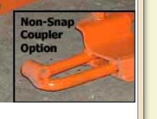
One of dislikes about the design is that I would prefer that both arms pivot separately. In the snap coupler design, pivot of the fixed arm is relative to the moveable snap coupler tongue. In the non-snap coupler design, it has a pipe welded across the tongue. Unless there is a lot of slop in the size of the hole, there would not be proper pivoting of the "fixed" arm. And I don't think you want a lot of slop in the hole for the pin hitch.
|
|
DrAllis
Orange Level Access
Joined: 12 Sep 2009
Points: 22740
|
Post Options
Thanks(0)
Quote Reply
Posted: 22 Mar 2023 at 10:58am |
|
Most of the time, each lift/draft arm ball would be at the same height. Moldboard plowing the right side is always an inch or more higher. That whole frame pivots in the snap-coupler bell when you want one lift/draft arm ball at a different height that the other lift/draft arm by changing the lift link length. I don't see a problem as long as it is a snap-coupler bell version.
Edited by DrAllis - 22 Mar 2023 at 10:59am
|
|
dfwallis
Orange Level
Joined: 09 Mar 2023
Location: DFW
Points: 925
|
Post Options
Thanks(0)
Quote Reply
Posted: 22 Mar 2023 at 11:02am |
DrAllis wrote:
Most of the time, each lift/draft arm ball would be at the same height. Moldboard plowing the right side is always an inch or more higher. That whole frame pivots in the snap-coupler bell when you want one lift/draft arm ball at a different height that the other lift/draft arm by changing the lift link length. I don't see a problem as long as it is a snap-coupler bell version.
|
Yes, but this would be the non-snap coupler version with a weld on mod which would prevent left to right swing as well as rotational swing.
Edited by dfwallis - 22 Mar 2023 at 1:07pm
|
|
dfwallis
Orange Level
Joined: 09 Mar 2023
Location: DFW
Points: 925
|
Post Options
Thanks(0)
Quote Reply
Posted: 22 Mar 2023 at 1:11pm |
dfwallis wrote:
DrAllis wrote:
Most of the time, each lift/draft arm ball would be at the same height. Moldboard plowing the right side is always an inch or more higher. That whole frame pivots in the snap-coupler bell when you want one lift/draft arm ball at a different height that the other lift/draft arm by changing the lift link length. I don't see a problem as long as it is a snap-coupler bell version.
|
Yes, but this would be the non-snap coupler version with a weld on mod which would prevent left to right swing as well as rotational swing.
|
I'm up against my spending limit for this year, but when I do this, provided I can devise a suitable drawbar mount modification (keeping the existing 1952 drawbar as is if possible), I'm leaning towards a drawbar mount version for the WD45, perhaps without the sway block (my drawbar mod might suffice for sway block). I tried sourcing the individual parts (arms, drawbar mount), but that cost was way higher than getting the equivalent kit and throwing away unneeded parts :(
|
|
steve(ill)
Orange Level Access
Joined: 11 Sep 2009
Location: illinois
Points: 90498
|
Post Options
Thanks(0)
Quote Reply
Posted: 22 Mar 2023 at 1:13pm |
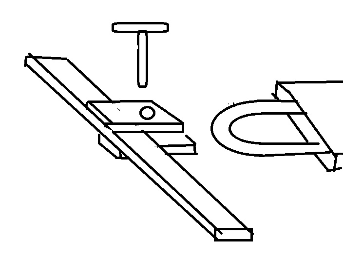
I see your point Gary... A Pin thru a steel bushing would not appear to have much "movement".. unless your "PIN HOLE" brackets are egg shaped for L-R swing.... Maybe Jim can explain more as he sells them.. Personally i would be temped to use the snap coupler version and make a "trailer hitch" type fitting on my crossbar under the tractor, then PIN thru the coupler loop.. That would give you movement L-R and Up- Down... but would take a little modification to your present hitch bar.
possible hitch design for snap coupler loop.
Edited by steve(ill) - 22 Mar 2023 at 1:23pm
|
|
Like them all, but love the "B"s.
|
|
dfwallis
Orange Level
Joined: 09 Mar 2023
Location: DFW
Points: 925
|
Post Options
Thanks(0)
Quote Reply
Posted: 22 Mar 2023 at 1:25pm |
steve(ill) wrote:
I see your point Gary... A Pin thru a steel bushing would not appear to have much "movement".. unless your "PIN HOLE" brackets are egg shaped for L-R swing.... Maybe Jim can explain more as he sells them.. Personally i would be temped to use the snap coupler version and make a "trailer hitch" type fitting on my crossbar under the tractor, then PIN thru the coupler loop.. That would give you movement L-R and Up- Down... but would take a little modification to your present hitch bar.
|
Yes. A slightly better design might be an add-on bracket that sandwiches the snap coupler tongue (top bracket and bottom bracket, with perhaps loose fitting bolts, one right in the inside circular bend of the tongue, one at the rear. Then the pin sleeve would be welded onto either bracket. That would preserve the integrity of the tongue as well. Being loose fitting, it could give you enough range of motion at least side to side.
|
|
steve(ill)
Orange Level Access
Joined: 11 Sep 2009
Location: illinois
Points: 90498
|
Post Options
Thanks(0)
Quote Reply
Posted: 22 Mar 2023 at 1:29pm |
|
yea... a added a drawing above that might be even easier.. use the BAR on the tractor to help limit movement fore- aft.
|
|
Like them all, but love the "B"s.
|
|
dfwallis
Orange Level
Joined: 09 Mar 2023
Location: DFW
Points: 925
|
Post Options
Thanks(0)
Quote Reply
Posted: 26 Mar 2023 at 8:27pm |
De-brushed...baby steps. Several days soaking in atf, still locked tite.
|
|
steve(ill)
Orange Level Access
Joined: 11 Sep 2009
Location: illinois
Points: 90498
|
Post Options
Thanks(1)
Quote Reply
Posted: 26 Mar 2023 at 9:04pm |
i dont know how your trying to ROTATE the motor ( bar/ crank).... but one good method is to jack on of the rear tires 2 inches off the ground and block under the drawbar or axle housing... put the transmission in gear, then try to ROCK the tire back and forth every couple days ( with the cylinders filled full of penetrant).
make sure when in Neutral that the tire will move.. That tells you the transmission is not locked up also..
Edited by steve(ill) - 26 Mar 2023 at 9:05pm
|
|
Like them all, but love the "B"s.
|
|
dfwallis
Orange Level
Joined: 09 Mar 2023
Location: DFW
Points: 925
|
Post Options
Thanks(0)
Quote Reply
Posted: 05 Apr 2023 at 5:51pm |
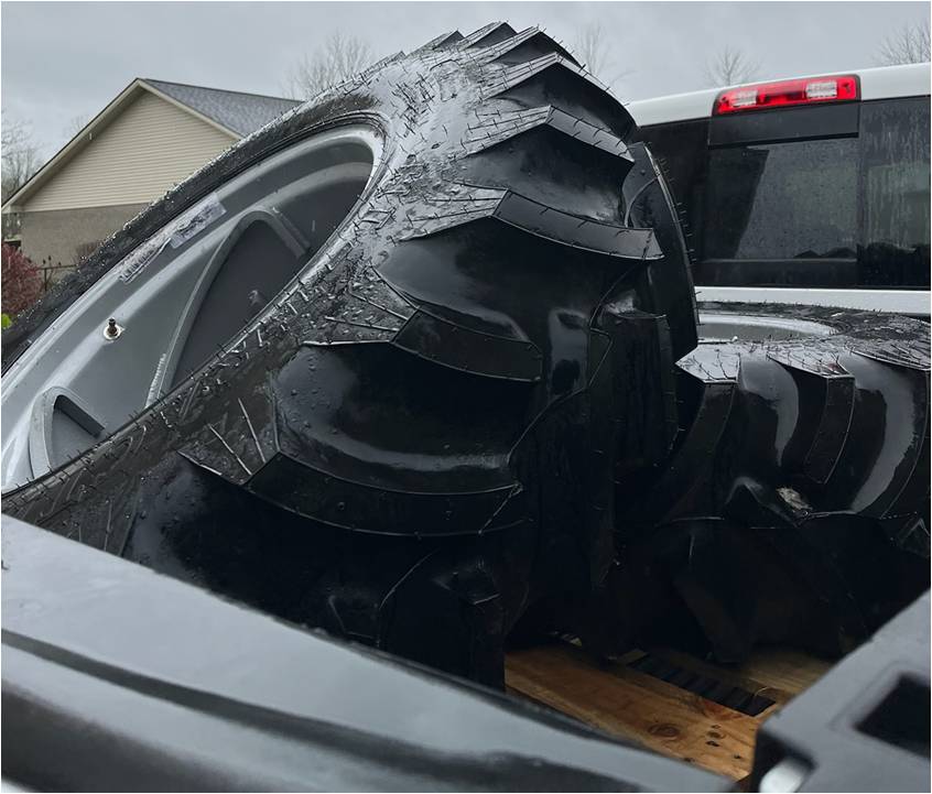
Baby steps...new 13.6 tires on 12 inch rims :)Probably not much more activity before May.
|
|
dfwallis
Orange Level
Joined: 09 Mar 2023
Location: DFW
Points: 925
|
Post Options
Thanks(0)
Quote Reply
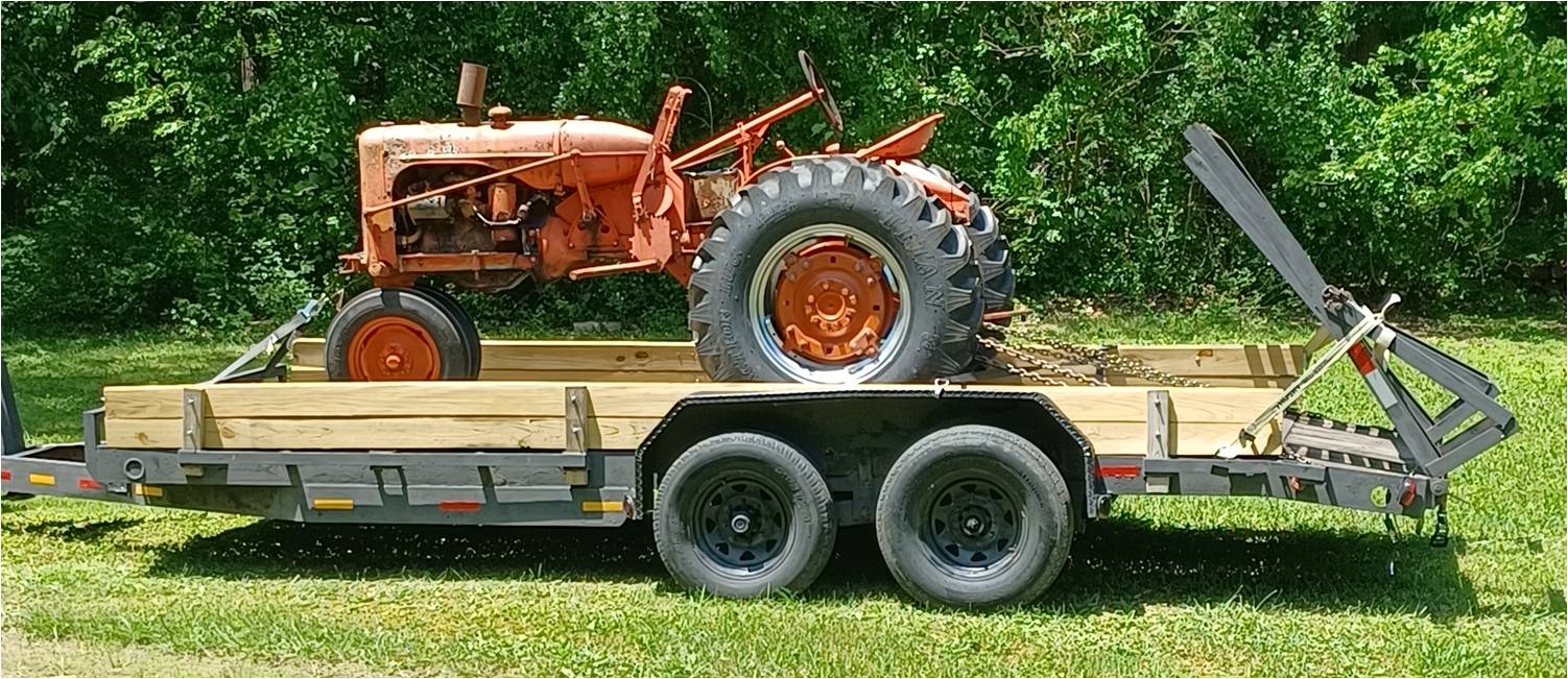
Posted: 28 May 2023 at 6:55pm |
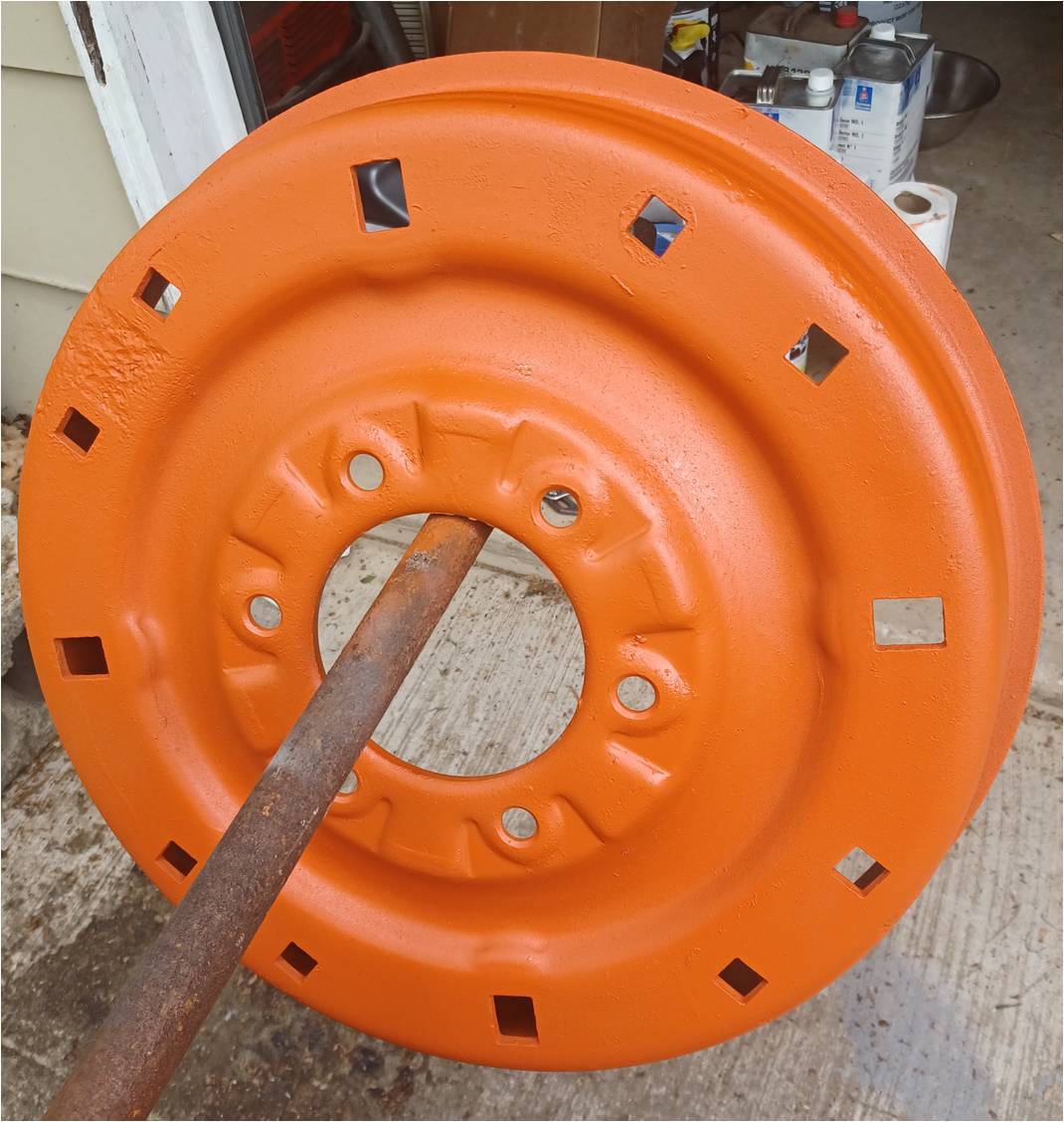
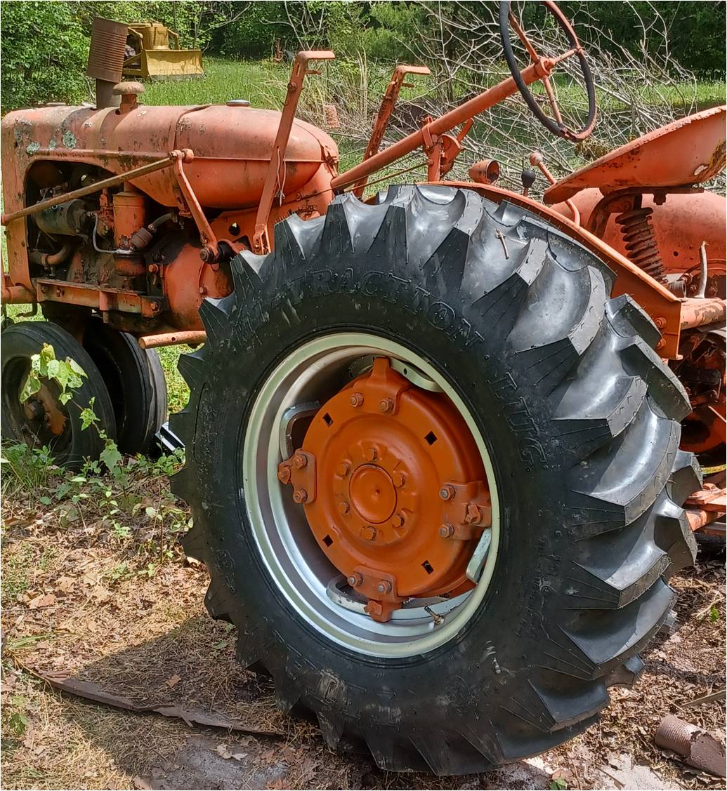
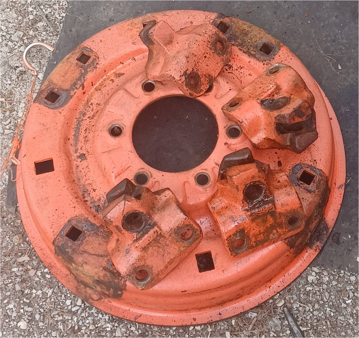
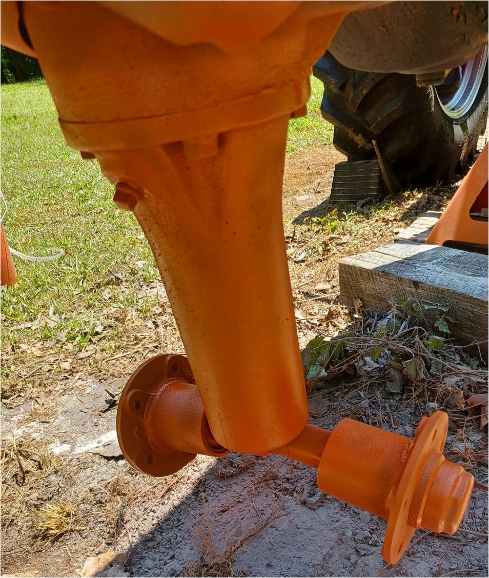
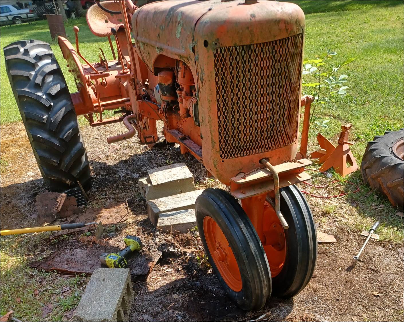
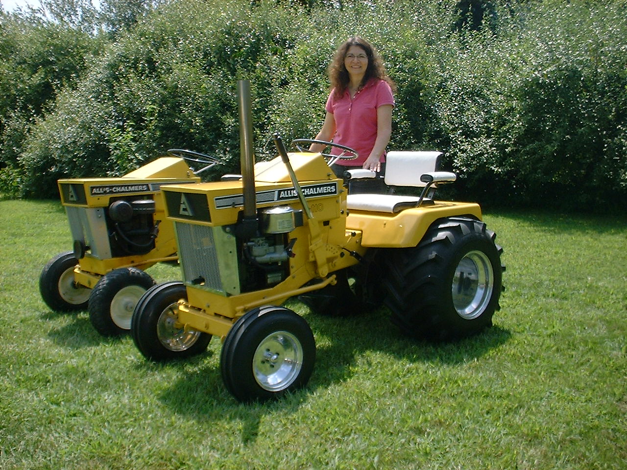
Some selected progress pics. New front and rear tires. New 12 inch rims on back with 13.6 Titans. New tires on front. Rims and front pedestal were sand blasted as was rear hubs and final drive near the wheels. One front rim was welded by dad in the mid 1960s. It's amazing that there's been almost no major deterioration since then. Only a few tiny pin holes near the original welds. The rear hubs and locks cleaned up very nicely. Only one of the lock bearing surfaces was slightly pock marked. All were very usable. All reassembled with anti-seize lube. The locks locked up tight. I was amazed how smoothly they operated. I stumbled upon the lock/lug wrench in the garage, and also the associated 5/8 inch lever bar. I painted them orange so I can remember them :) Everything was sand blasted primed and painted. Some key areas like inside the front rims have approximately 10 coats rust reformer and of paint in total. The inside of the front rims were a bit flakey (rust) but with angle grinder, wire brush, and sand blaster, they came out decent and smooth. Tire guy had no qualms with them. I may eventually replace the front rims, or maybe just the welded one which doesn't look as nice. The tractor has been moved to a garage for engine assessment. It will get rebuilt regardless, but there may need to be a section of the block re-welded. Dad welded it in the early 70's (or thereabouts) but did not have the right welding equipment on-site at the time so it continued to have a slow coolant leak. Believe the weld is intact though.
The starter motor was removed for unknown reason, but I tested it and it is fine with not a single issue with the gear teeth or throwout. Was inside the garage for 40 years. The original generator is another story. Was in pieces with coils toasted and loose. Believe I can get it rewound locally. I inspected part of the flywheel which seems fine where I could view. I think the transmission is ok but could only get it into reverse for the trailer ride. One brake seems functional, sort of, the other seems to be rubbing full time but not forcefully and the pedal won't depress beyond an inch or so. I can see a broken spring which may be wedged in the way. Steering play seems no worse than I remember it. I remember that the front rim welds were heavy enough to cause a little wobble at full speed. I found the ammeter and control panel. The control panel cleaned up nicely, but all switches and ammeter were toast so I'll be rebuilding that, cleaning up the starter (maybe more if needed), and the generator if I can. I'll probably use stainless fasteners in key exposed places. Nearly all electrical wiring seems haphazard. It seems to have had a regulator installed at some point, but no reference in my service manual so I'll have to research that further.
|
|
dfwallis
Orange Level
Joined: 09 Mar 2023
Location: DFW
Points: 925
|
Post Options
Thanks(0)
Quote Reply
Posted: 28 May 2023 at 6:58pm |
|
I should have repacked the front bearings. One was fine but the other had slight end play. They both rotate smoothly. Was running out of time this trip. Needed to get some other things in besides the tractor. I painted the backside of the fenders to retard rust, but they'll need some straightening work at some point. They seem salvageable with only straightening required as far as I've seen so far.
Edited by dfwallis - 28 May 2023 at 9:20pm
|
|
wjohn
Orange Level

Joined: 19 Jan 2010
Location: KS
Points: 2379
|
Post Options
Thanks(1)
Quote Reply
Posted: 28 May 2023 at 11:03pm |
|
Looks like good progress. Are the cultivators still hanging around somewhere?
|
|
1939 B, 1940 B, 1941 WC, 1951 WD, 1952 CA, 1956 WD-45
|
|
IBWD MIke
Orange Level

Joined: 08 Apr 2012
Location: Newton Ia.
Points: 4264
|
Post Options
Thanks(1)
Quote Reply
Posted: 29 May 2023 at 6:28am |
|
Looks good! I need to get to work on both of my CA's.
|
|
steve(ill)
Orange Level Access
Joined: 11 Sep 2009
Location: illinois
Points: 90498
|
Post Options
Thanks(0)
Quote Reply
Posted: 29 May 2023 at 8:59am |
the original battery was 6 volt and just had a CUT OUT SWITCH box mounted to the generator.. No voltage regulator.. The LIGHT SWITCH had a resistor on it that grounded the "F" wire from the generator to give a low amp charge.. When the switch was ON, the "F" was grounded around the resistor to get a GOOD GROUND and MORE AMP charge..
It was not uncommon to remove the light switch and put a 6 volt regulator near the generator and let it do the job.... If the battery was changed to 12v, then yes, you need a regulator to handle the job.
Edited by steve(ill) - 29 May 2023 at 9:03am
|
|
Like them all, but love the "B"s.
|
|
dfwallis
Orange Level
Joined: 09 Mar 2023
Location: DFW
Points: 925
|
Post Options
Thanks(0)
Quote Reply
Posted: 29 May 2023 at 9:48am |
wjohn wrote:
Looks like good progress. Are the cultivators still hanging around somewhere? |
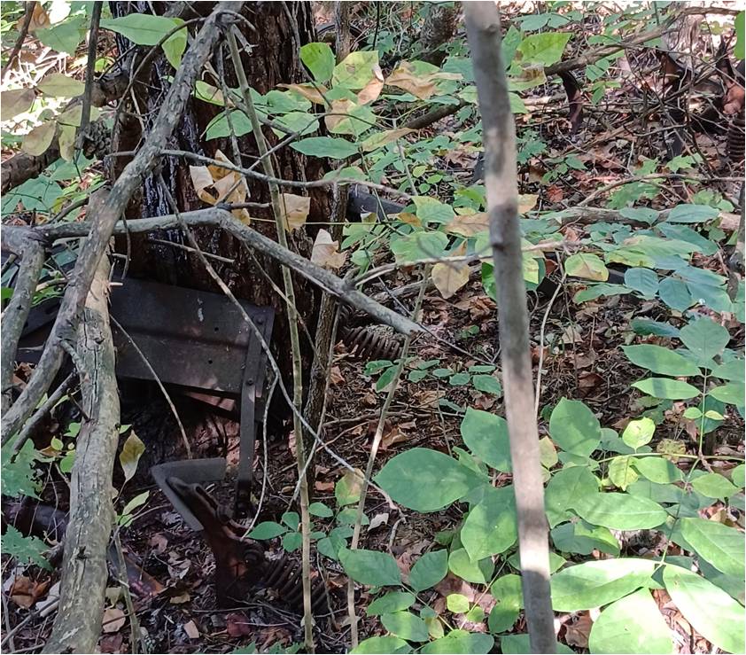
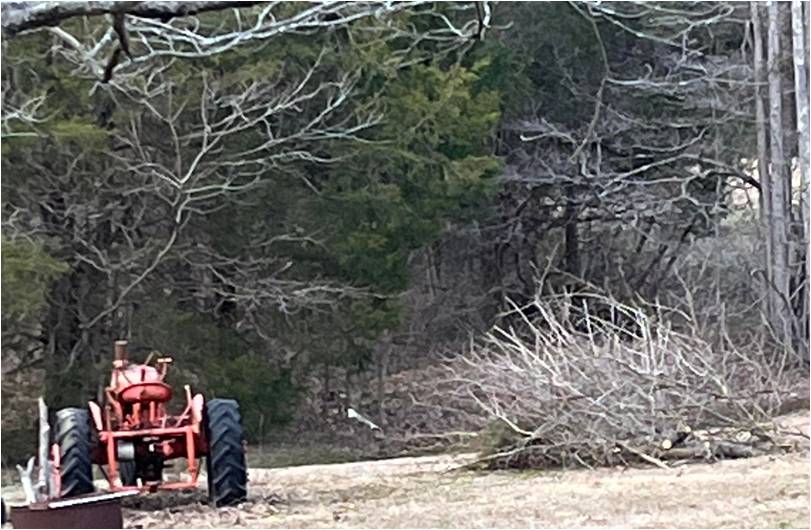
I found front and rear cultivators, disc, plow, and planter. The cultivators are in the worst shape probably. Lots of trees growing through it. One of the sweeps is exactly in the middle of a 1.5 foot diameter scotch pine tree at ground level. It seems to be sideways. Couldnt see enough to see if its twisted or just on its side. It didn't quite logically compute.
Edited by dfwallis - 29 May 2023 at 2:00pm
|
|
dfwallis
Orange Level
Joined: 09 Mar 2023
Location: DFW
Points: 925
|
Post Options
Thanks(0)
Quote Reply
Posted: 29 May 2023 at 9:53am |
steve(ill) wrote:
the original battery was 6 volt and just had a CUT OUT SWITCH box mounted to the generator.. No voltage regulator.. The LIGHT SWITCH had a resistor on it that grounded the "F" wire from the generator to give a low amp charge.. When the switch was ON, the "F" was grounded around the resistor to get a GOOD GROUND and MORE AMP charge..
It was not uncommon to remove the light switch and put a 6 volt regulator near the generator and let it do the job.... If the battery was changed to 12v, then yes, you need a regulator to handle the job.
|
It's 6 volt. Plan to keep it that way. The regulator was mounted just behind the starter motor. I don't remember it at all, so maybe my uncle added it in the 70s.
|
|
dfwallis
Orange Level
Joined: 09 Mar 2023
Location: DFW
Points: 925
|
Post Options
Thanks(0)
Quote Reply
Posted: 19 Jun 2023 at 8:41pm |
|
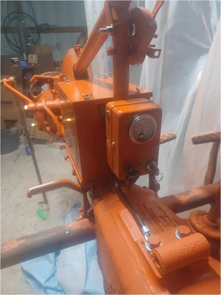
Got a fairly good look at the engine block. The block was welded in several spots 50 years ago. Looks pristine, welds held, finished flat, good head gasket seals. I think it's going to be ok.
|
|
Steve in NJ
Orange Level Access
Joined: 12 Sep 2009
Location: Andover, NJ
Points: 12071
|
Post Options
Thanks(0)
Quote Reply
Posted: 20 Jun 2023 at 5:34pm |
if you need a new wiring system for that project, visit our website. We do everything electrical and touch on each area of the Tractor. I do Carb, Generator, Alternator, 3 position switch and Starter rebuilding. Be happy to help you out with anything....
Steve@B&B bb-customcircuits.com
|
|
39'RC, 43'WC, 48'B, 49'G, 50'WF, 65 Big 10, 67'B-110, 75'716H, 2-620's, & a Motorhead wife
|
|
dfwallis
Orange Level
Joined: 09 Mar 2023
Location: DFW
Points: 925
|
Post Options
Thanks(0)
Quote Reply
Posted: 20 Jun 2023 at 7:15pm |
Steve in NJ wrote:
if you need a new wiring system for that project, visit our website. We do everything electrical and touch on each area of the Tractor. I do Carb, Generator, Alternator, 3 position switch and Starter rebuilding. Be happy to help you out with anything....
Steve@B&B bb-customcircuits.com
|
Already bought one of your rebuilt switches. Generator was toast, being completely rebuilt and converted to regulator style operation. Starter was in very good condition, but I opted to have him recondition it as well. Fort Worth Starter and Generator. I'll be doing the new wiring harness myself. Already have it.
|
|
dfwallis
Orange Level
Joined: 09 Mar 2023
Location: DFW
Points: 925
|
Post Options
Thanks(0)
Quote Reply
Posted: 24 Sep 2023 at 7:24pm |
Progress pics 9/24/2023:
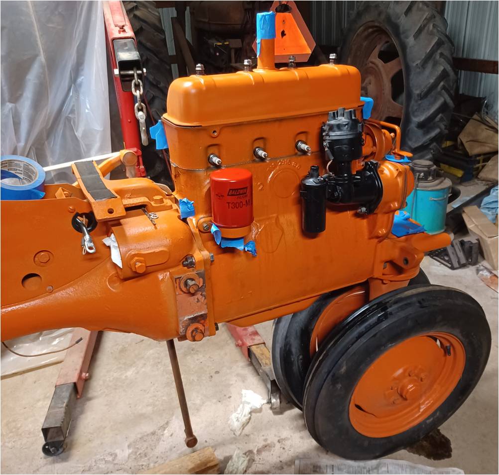
While engine block was out to the machine shop, I prepared the front half. Sheet metal was taken to a body shop for some rip and dent repairs. Installed a new throwout bearing although the old one wasnt really very bad. Clutch plate was relatively new. Also ran a new wiring harness.
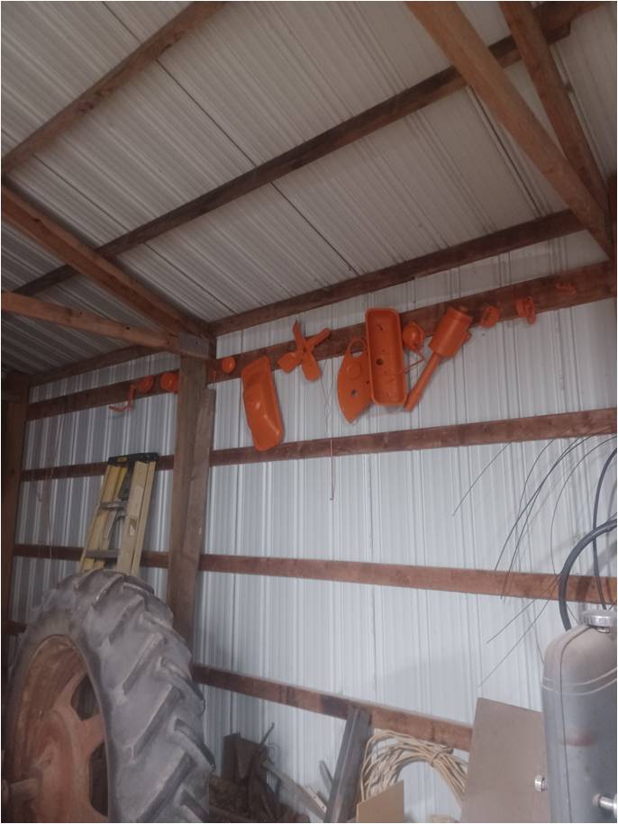
Since the engine work is taking a little longer, I stored the parts along the roofline by the H. I cleaned and painted EVERYTHING. New bolts and studs where needed.
Crankshaft had some minor pitting but overall wasnt that bad. Machined everywhere needed. Had too much end play when we got it back so we sent it back out for more work. Originally, the machine shop documented the wrong specs on the work tag so we ordered the wrong bearings and had to do that over as well. Those issues were the source of most of the delay in getting the engine going. I had high hopes, but it didn't happen. Work is ongoing as time permits. No the M doesn't run either :(
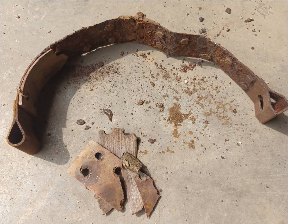
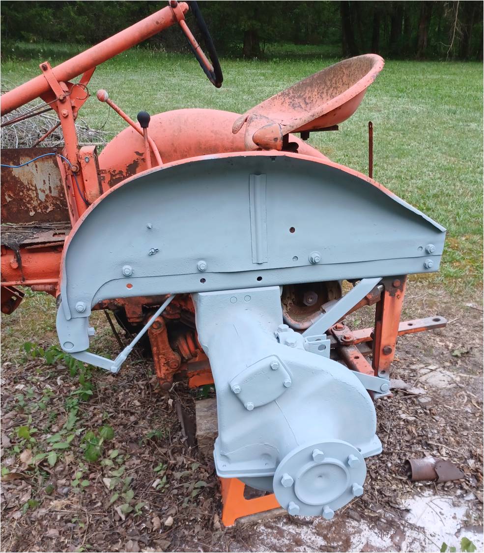
After I got most of the front half ready for the engine install (minus sheet metal), I replaced the brake pads. This is the "good" one. The left one was rusted in two at the hinge. Kind of a chore to get all the rat and mud dauber nests out through those cubby holes. Must have pulled 2 gallons of junk out of there. The drums should probably be worked on but I think they'll be fine besides wearing the pads out a little faster. There was plenty of metal left. Probably because it hasn't had properly adjusted brakes since the 60s (i.e. little contact).
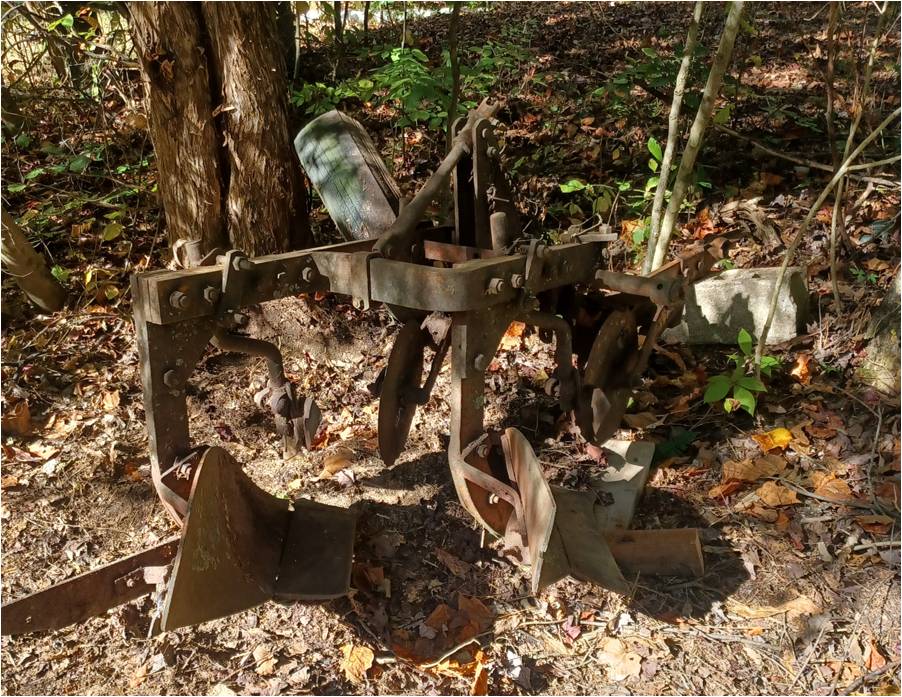
I was able to get the plow up out of the dirt and on some temporary blocks (I ran out of time and just used whatever I could find). The frame looks like it will clean up ok. The plowshare/moldboards are broken. The pieces seem to be lying around in the garage, could probably be welded up (or replaced).
Here's the cultivator previously mentioned as having a tree growing around it. That will be fun to remove.
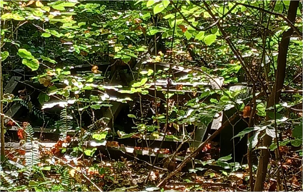
And the disk. Didn't get a picture of the planter (forgot when I decided to de-tree the bulldozer).
Edited by dfwallis - 24 Sep 2023 at 7:25pm
|
|
IBWD MIke
Orange Level
Joined: 08 Apr 2012
Location: Newton Ia.
Points: 4264
|
Post Options
Thanks(1)
Quote Reply
Posted: 25 Sep 2023 at 5:28am |
|
That paint is looking pretty spiffy!
|
|
ACinSC
Orange Level
Joined: 16 Dec 2015
Location: South Carolina
Points: 3243
|
Post Options
Thanks(1)
Quote Reply
Posted: 25 Sep 2023 at 6:18am |
|
Looking good! Thanks for sharing
|
|
dfwallis
Orange Level
Joined: 09 Mar 2023
Location: DFW
Points: 925
|
Post Options
Thanks(0)
Quote Reply
Posted: 25 Sep 2023 at 8:32am |
IBWD MIke wrote:
That paint is looking pretty spiffy!
|
3 coats of primer and 3 coats of orange. 4 and more coats of primer or orange in strategic areas.
|
|
dfwallis
Orange Level
Joined: 09 Mar 2023
Location: DFW
Points: 925
|
Post Options
Thanks(0)
Quote Reply
Posted: 16 Oct 2023 at 11:28am |
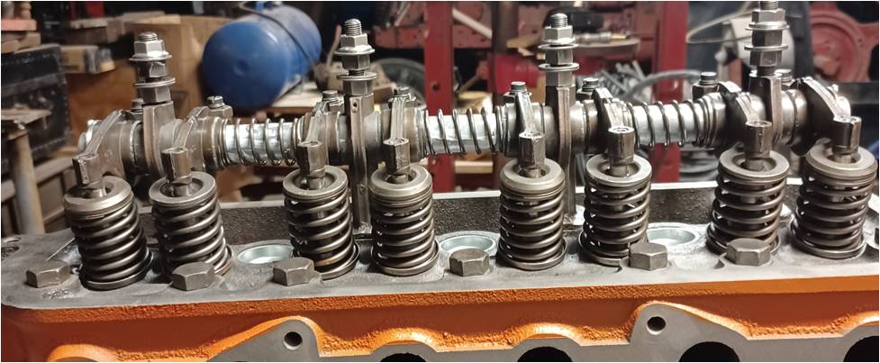
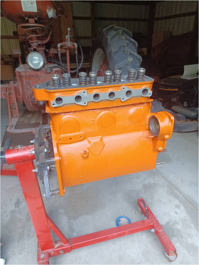
10/16/2023 Update: Further engine work. Engine rebuild internals complete. Everything to spec except liner protrusion. Two slightly exceed the 0.005 max with light torque, but improve when fully torqued. Basically, they don't sit perfectly flat with the block surface. Pretty sure it will be fine.
A better view of the improved rocker arm alignment. This is a massive improvement of horizontal alignment. Some were in contact with less than half of the valve stem previously. It's actually better than it looks in this pic due to parallax.
Edited by dfwallis - 16 Oct 2023 at 11:29am
|
|
JK in Pa
Bronze Level


Joined: 12 Sep 2009
Location: Dushore, Pa.
Points: 166
|
Post Options
Thanks(0)
Quote Reply
Posted: 16 Oct 2023 at 3:23pm |
|
I believe I see valve rotators on the exhaust valves. I always thought valve rotators required offset rockers.
|
|