| Author |
|
smokey 
Orange Level


Joined: 04 Oct 2010
Location: Michigan
Points: 287
|
 Post Options Post Options
") Thanks(0) Thanks(0)
 Quote Quote  Reply Reply
 Posted: 04 Jan 2012 at 7:21am Posted: 04 Jan 2012 at 7:21am |
|
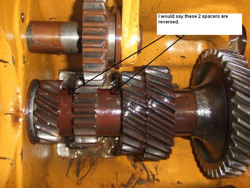
pre64, in your picture of the cover I see what looks like 2 shim washers on the rail in the book does not show them, and with the wear on 1st- and reverse idler leading edge's it don't look right, the shims on the counter looks like the front spacer should be (0.868) and the rear should be (0.966)
|
 |
|
Sponsored Links
|
|
|
Orange Blood
Orange Level

Joined: 29 Nov 2010
Location: ColoradoSprings
Points: 4053
|
Post Options
Thanks(0)
Quote Reply
Posted: 04 Jan 2012 at 8:07am |
|
This morning I took an inspection mirror and looked at mine, the spacer in front is about 3/8" wide, and the one in the rear is about 7/8" wide, these are rough guesses as I couldn't get anything in there to measure them. When the tranny is in 1st gear, the reverse gear should be all the way rearward up against the back mainshaft gear, and there was about 3/16" or maybe a 1/4" of clearance between the countershaft reverse and the reverse idler gear, with the spacers reversed, they would probably mesh.
|
|
Still in use:
HD7 WC C CA WD 2-WD45 WD45LP WD45D D14 3-D17 D17LP 2-D19D D19LP 190XTD 190XTLP 720 D21 220 7020 7030 7040 7045 3-7060
Projects: 3-U UC 2-G 2-B 2-C CA 7-WC RC WDLP WF D14 D21 210 7045 N7
|
|
pre64
Bronze Level

Joined: 04 Oct 2010
Location: Cable OH
Points: 34
|
Post Options
Thanks(0)
Quote Reply
Posted: 04 Jan 2012 at 11:46am |
|
Well fellows we will know shortly. Just got it split and the power director off. As soon as I eat a bite I will be pulling the main shaft and working my way down. Should know something in a few hours.
|
|
pre64
Bronze Level
Joined: 04 Oct 2010
Location: Cable OH
Points: 34
|
Post Options
Thanks(0)
Quote Reply
Posted: 04 Jan 2012 at 11:51am |
Dr Allis, Thanks for your tip. Don't ever recall doing one that way but it sounds possible. I have already spilt the tractor so I am going in and making sure everything else is correct as well as perform a good inspection. I am also hoping to take some pictures of the problem before and after it is corrected. Thanks Tim
|
|
pre64
Bronze Level
Joined: 04 Oct 2010
Location: Cable OH
Points: 34
|
Post Options
Thanks(0)
Quote Reply
Posted: 04 Jan 2012 at 3:39pm |
|
I didn't realize that the top gears would't come out the front. It has been 30 years plus since I have been in the transmission part of it. I was able to get the end gear and slider off but that is it. I also notice a brand new soft plug over the counter shaft that we suspected was the culpret. Imagine that. I am done for the day so tomorrow I will pull the drives and rear end so I can remove the pinion . I am hoping to get the top main shaft out of the way so I can get a clear picture of the problem for others to see. Hopefully it may prevent someone else from going through this headache. I don't know how you could ever do a major overaul on a transmission and not check your work during assembly.
Edited by pre64 - 04 Jan 2012 at 8:33pm
|
|
SteveM C/IL
Orange Level Access
Joined: 12 Sep 2009
Location: Shelbyville IL
Points: 8965
|
Post Options
Thanks(0)
Quote Reply
Posted: 04 Jan 2012 at 10:07pm |
|
some folks should'nt be parents and some should'nt be mechanics....but, that's the way it is
|
|
pre64
Bronze Level
Joined: 04 Oct 2010
Location: Cable OH
Points: 34
|
Post Options
Thanks(0)
Quote Reply
Posted: 06 Jan 2012 at 2:17pm |
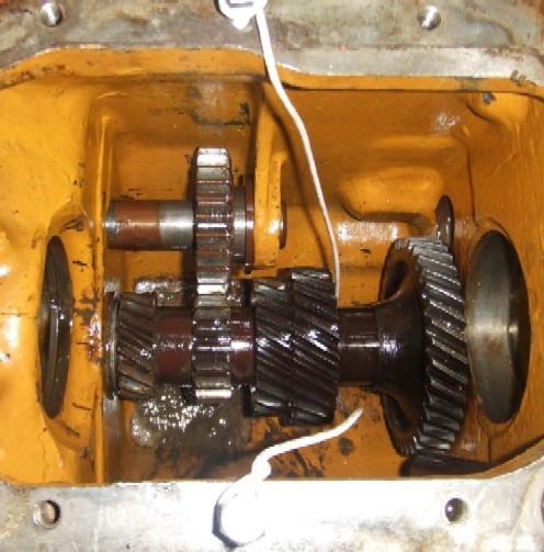
I didn't get to work on this yesterday as planned, but I got it tore down today. Take a look at this picture and tell me if you agree with me the 2 spacers are reversed? Thanks Tim
Edited by pre64 - 06 Jan 2012 at 7:53pm
|
|
Dave (Mid-MI)
Orange Level

Joined: 12 Sep 2009
Location: Hemlock, MI
Points: 576
|
Post Options
Thanks(0)
Quote Reply
Posted: 06 Jan 2012 at 3:10pm |
|
Yup.
|
|
pre64
Bronze Level
Joined: 04 Oct 2010
Location: Cable OH
Points: 34
|
Post Options
Thanks(0)
Quote Reply
Posted: 06 Jan 2012 at 5:08pm |
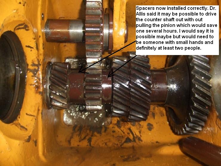
Dr. Allis I see what you mean by driving out the counter shaft to replace the bearings and races. I think however it would be very difficult to slide the shaft out far enough to pull 2 gears and spacers off and change them around. If you work alone as I do I would say no, however if you had a couple of extra hands and they were small I would say maybe on a lucky day. Small hands and lucky days seem to flee from me however. I have posted a before and after picture of the spacers being in the wrong location. I want to thank you for all of your help. Hopefully others have learned as well. Thanks Tim
|
|
SteveM C/IL
Orange Level Access
Joined: 12 Sep 2009
Location: Shelbyville IL
Points: 8965
|
Post Options
Thanks(0)
Quote Reply
Posted: 06 Jan 2012 at 5:14pm |
|
You'd have thought the person responsible for the mistake would have noticed it after together and groaned and fixed it.
|
|
Gary in da UP
Orange Level
Joined: 13 Sep 2009
Location: EUP of Mi.
Points: 1885
|
Post Options
Thanks(0)
Quote Reply
Posted: 06 Jan 2012 at 5:25pm |
 SteveM C/IL wrote: SteveM C/IL wrote:
You'd have thought the person responsible for the mistake would have noticed it after together and groaned and fixed it. |
Yes, you and I think alike, but not everyone has to sign-off on their work or feels compelled to do their work to a standard. Too bad , it causes a lot of grief for the innocent !
|
|
pre64
Bronze Level
Joined: 04 Oct 2010
Location: Cable OH
Points: 34
|
Post Options
Thanks(0)
Quote Reply
Posted: 06 Jan 2012 at 5:26pm |
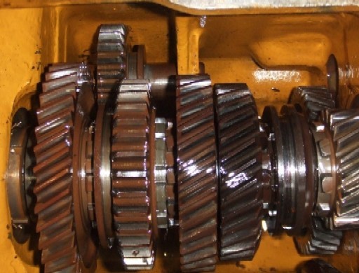
Here are the before and after pictures of the spacers on the counter shaft. My advise to all is to pay attention and take pictures of all of the parts if you are going to rebuild a transmission yourself. Some poor soul probably paid some several thousand dollars for this repair and it was done wrong.
|
|
SteveM C/IL
Orange Level Access
Joined: 12 Sep 2009
Location: Shelbyville IL
Points: 8965
|
Post Options
Thanks(0)
Quote Reply
Posted: 06 Jan 2012 at 5:33pm |
|
well,the bright side to the story is you didn't have to buy hard parts to fix it
|
|
Orange Blood
Orange Level
Joined: 29 Nov 2010
Location: ColoradoSprings
Points: 4053
|
Post Options
Thanks(0)
Quote Reply
Posted: 06 Jan 2012 at 5:54pm |
|
Glad you got it headed to working properly, sorry you had to tear into it so far, but as Steve pointed out, no hard parts, just a few gaskets and seals.
|
|
Still in use:
HD7 WC C CA WD 2-WD45 WD45LP WD45D D14 3-D17 D17LP 2-D19D D19LP 190XTD 190XTLP 720 D21 220 7020 7030 7040 7045 3-7060
Projects: 3-U UC 2-G 2-B 2-C CA 7-WC RC WDLP WF D14 D21 210 7045 N7
|
|
pre64
Bronze Level
Joined: 04 Oct 2010
Location: Cable OH
Points: 34
|
Post Options
Thanks(0)
Quote Reply
Posted: 06 Jan 2012 at 7:23pm |
I want to thank all of you for your input and help on this. Normally we always say it should be something simple....this time we proved the theory wrong. Other than buying some gaskets and seals cost wise won't be so bad but if I add my 4.50 per hour shop rate to it I will have to sell my dog. :) . Thanks again Tim
|
|
allischalmerguy
Orange Level

Joined: 11 Sep 2009
Location: Deep River, IA
Points: 2895
|
Post Options
Thanks(0)
Quote Reply
Posted: 06 Jan 2012 at 10:13pm |
|
I have been following this post, it has been educational and very interesting to me. Thanks for all the information and way to go Tim on getting it solved!!!!
Pastor Mike
|
|
It is great being a disciple of Jesus! 1950 WD, 1957 D17...retired in Iowa,
|
|
Orange Blood
Orange Level
Joined: 29 Nov 2010
Location: ColoradoSprings
Points: 4053
|
Post Options
Thanks(0)
Quote Reply
Posted: 06 Jan 2012 at 10:25pm |
Hey Tim,
Where do you get $4.50, an hour from, I am lucky if I don't have to pay to work in my own shop? :-)
|
|
Still in use:
HD7 WC C CA WD 2-WD45 WD45LP WD45D D14 3-D17 D17LP 2-D19D D19LP 190XTD 190XTLP 720 D21 220 7020 7030 7040 7045 3-7060
Projects: 3-U UC 2-G 2-B 2-C CA 7-WC RC WDLP WF D14 D21 210 7045 N7
|
|
Chalmersbob
Orange Level
Joined: 11 Sep 2009
Location: Pennsylvania
Points: 2122
|
Post Options
Thanks(0)
Quote Reply
Posted: 07 Jan 2012 at 9:05pm |
At $4.50 per hour, you can work in my shop any time you want to.
Glad to hear that you solved your problem, now on to the next. Bob
|
|
Pat the Plumber CIL
Orange Level

Joined: 11 Sep 2009
Location: Springfield,Il
Points: 4988
|
Post Options
Thanks(0)
Quote Reply
Posted: 08 Jan 2012 at 7:46pm |
|
Thanks for posting subject and pictures. This is why this is the best site on the internet
|
|
You only need to know 3 things to be a plumber;Crap rolls down hill,Hot is on the left and Don't bite your fingernails
1964 D-17 SIV 3 Pt.WF,1964 D-15 Ser II 3pt.WF ,1960 D-17 SI NF,1956 WD 45 WF.
|
|
DaveKamp
Orange Level Access
Joined: 12 Apr 2010
Location: LeClaire, Ia
Points: 6117
|
Post Options
Thanks(0)
Quote Reply
Posted: 08 Jan 2012 at 7:57pm |
|
Hee hee... isn't it cool that we can live vicariously through eachother's tribulation? Better yet, we can post pictures showing it, just as we found it, and after, we fixed it...
Congratulations, Tim- job well done! It may take small hands, but then again, it may be a case where special tools MAY knock that rascal out without breaking it all down.
I'll be working on a WD transmission in the future... the experiences shared here, along with the photos, will help me immensely. Thanks Everybody!
|
|
pre64
Bronze Level
Joined: 04 Oct 2010
Location: Cable OH
Points: 34
|
Post Options
Thanks(0)
Quote Reply
Posted: 09 Jan 2012 at 6:39am |
Thanks everyone for the comments. Had it not been for this site and everyones willingness to aide a fellow Allis collector, things may have turned out much different. I will be posting a couple of more pictures this week of assembly and some pointers for doing the entire job alone that will hopefully aide some of you in the same situation. I work alone 99% of the time so I am use to developing tools and tricks for helping me through it. I have now assembled the counter shaft gears and reinstalled the pinion shaft and main gears, and tried all gears to assure they are working correctly. I know a couple of you are wondering if I cleaned out the crud down in the housing that shows up in the picture and yes I did. I am at a stand still now waiting on seals and gaskets and hopefully will have them by the weeks end. More to come! Tim
Edited by pre64 - 09 Jan 2012 at 6:57am
|
|
Coming up in the near future: another D17, 2-B's,WC styled, WC unstyled,2 snap coupler 3 bottom plows, pull type shredder,and 2 belly mowers.
|
|
jaybmiller
Orange Level Access
Joined: 12 Sep 2009
Location: Greensville,Ont
Points: 25180
|
Post Options
Thanks(0)
Quote Reply
Posted: 09 Jan 2012 at 7:51am |
Man , what a painful learning experience( even from the sidelines ) !
I've always been impressed with the knowledge that you guys freely share and those 2 pictures showed WHY we should always take pictures before we tear into something and ASK before commiting to putting it all back together with fingers crossed, hoping this is the right way
|
|
3 D-14s,A-C forklift, B-112
Kubota BX23S lil' TOOT( The Other Orange Tractor)
Never burn your bridges, unless you can walk on water
|
|
TomMN
Orange Level

Joined: 13 Sep 2009
Location: Elbow Lake, MN
Points: 858
|
Post Options
Thanks(0)
Quote Reply
Posted: 09 Jan 2012 at 9:09am |
|
Those pictures are worth a thousand words for sure. I like to have the manuals when I tackle these things. I just checked and with either the parts book or the service manual this shouldn't have happened. The service manual for the WD45 even gives the width of these spacers, the two wider ones are .966 wide and the small one is .654 wide. I remember I had to shim mine up to tighten the countershaft properly. The only adjustment is different width snap-rings to set the end play at .000 to .004. Thanks for the great detail on what this problem turned out to be.
|
|
pre64
Bronze Level
Joined: 04 Oct 2010
Location: Cable OH
Points: 34
|
Post Options
Thanks(0)
Quote Reply
Posted: 09 Jan 2012 at 4:17pm |
D17 Transmission Disassembly Tools and Techniques I was going to start a new thread for tips
and tools for splitting and disassembly of the D17 transmission, but I am going
to inlcude it here.
If the moderator wishes to have it moved let
me know. This is not a complete instruction guide and may vary between
applications. This is merely some things that
I have done that have helped me when no help was around.
First thing is get a good manual and do your homework.
When you find things left out or issues, come here to get your answers! You won’t find a better helping forum.
When you are ready to begin make sure you
have adequate tools and room to complete
the task. This is where the books don't help much. Many of us do not have expensive
state of the art equipment just sitting around waiting to be used. I am
fortunate enough to have a small shop with mills lathes and drill presses etc
and normally a fair supply of iron around.
If you don't have these items then it will take you just a little more time is
all.
This method is only as safe as the person performing. Please keep safety
in your work at all times.
For my method the following tools are needed to complete the task. Your list may
vary but the basics will be similar: At least 1 large floor jack, 2 large jack
stands, engine hoist and some misc blocking and a digital camera (your very best friend).
I like to use the engine stand for
splitting, moving parts around, and pulling the rear differential housings and
axles. Also a tip for working alone, I spent about 100.00 bucks and put an air
lift cylinder on my engine hoist which gives you great control and allows you
to multi task.
Once you have read your manual and
you feel comfortable or brave enough to proceed you will probably discover that
it doesn't always go as planned. The "book" says support both parts
of the tractor being split, remove the bolts and just roll the tractor away.
That is all fine and dandy when they wrote the book 50 years ago, but things do
weather over time and changes the way we do things. You may very well notice
that after doing all of the things the book says the tractor is still stuck
together and won't budge. You can't hook you 4 wheel drive pickup to it and
yank it apart, there is no opening for you to get a prybar or a screwdriver between the housings so what next? I do not recommend lowering your front half
down to try and break it away that way, you are asking for trouble. If all else
fails this is what I do: (I may get some fellow mates to disagree on this but
it does work). Find an inconspicuous place on the side of the housing close to
the bottom and take your angle grinder with a thin cut off blade on it, and
make a small indentation (cut) between the two housings. This will allow you to
get a small prybar or similar between the cracks and force
the gasket apart.
The next thing you will discover when
splitting is you will begin to run out of jacks, jackstands etc to support all
of the heavy parts. Rather than getting a bigger stack of 2x4's and trying to
support a couple of ton of iron with the risk of killing yourself, here is what
I do for very little money. Once you have the transmission split from the
differential I start rounding up to 2 or 3 inch angle iron long enough to fit
to the top of the transmission housing around 3 feet or so. Next if you don't
have an end mill to make exact holes, measure the distance between one of the
top holes on the side and one of the
bottom holes on the same side and drill you a couple of "oversize
holes" in the angle to match these. Your not going to get them exact so
over drill them at least two or three sizes too big so you can offset the
difference, you don't care how they look just so they are safe. Now put bolts
through both holes and tighten them up and the same for the opposite side of
the transmission. You now have your front supports and eventually will free up that floor jack.
Using the same technique make two more in the same fashion for the other half
you just split and bolt them in place. Now you can ease your floor jack off and
free it up. When you move to the rear to remove your Lift Arm Housing ,place your jack in the center back and remove your lift arm housing. Get a good long strap and secure a loop around the lift arm housing from your engine hoist and center it so it doesn't get away from you when it breaks loose. You read your book right? So you have already pulled your pto shaft and unhooked and removed your lift cylinder. Now if the housing is stuck and you can not get a pry bar in anywhere then you may have to use your angle grinder again as we did before. Once it is down and out of the way you can access the differential components. Before you proceed you need to make at least one more angle iron leg brace to place on the the back of the housing so you can get your jack out of the way to clean up all the oil that leaked out. This leg you can get by using one bolt and line up the other hole with the guide pin sticking out. This will save you a little time and work and once you tighten it, it will be safe and secure. Keep following your book and remove the rear axle housings very carefully, preferably with the engine hoist and strap and move aside. If the drum came out with it pull if off the shaft and put aside. With both axles removed you are ready to remove the ring gear assembly. Before you start get you a couple of large dowels, broom handle etc and put in the ends of the ring gear assembly through the side holes so it doesn't fall when you remove the bearing housings next. Follow the book and remove the bolts from the axle housing bearing retainers. These housings have an oring seal and are
about 2 bucks from Allis so don't consider reusing them. You will need to take
a brass punch or small block of wood inside the differential housing and tap
out the bearing housings outward until they are free. Once the oring is out of
the housing they will come off easy. Make sure you replace the seals in the
housing before reinstalling. Your ring gear assembly is now free. It is heavy
and sharp so some gloves may be nice. You will need to hold it up and pull the
dowels at the same time. When you remove it bring it straight back out the
rear. There is not much clearance here!
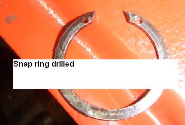
Next you will be ready to remove your hand
clutch and the main input shaft according to the instructions. You will notice
that most likely your will encounter snap rings that have no holes in them to
remove them and not enough room to get anything else in their to aid in getting
them off the shaft. What I do now is get a small, good sharp center punch and
mark each side of the snap ring and drill the two holes in them. Keep it under
an 1/8" and centered or it will be too close to the edge. Now you can use
your regular snap ring pliers to remove it and possibly save it. The material
of the ring is a little hard so make sure you have a good fresh bit to drill
with, but a regular steel bit will work.
The book says to just tap the main shaft
out the rear housing. Hope yours comes right out but I bet it don't. It may
take a lot of tapping to drive it out. Mine came out hard all the way to the
end. You have a double roller bearing with a couple of inches of surface so a
normal tap isn't going to cut it. If you do not have a large brass shaft or
punch you will probably need to find a small oak 4x4 and a 3 lb hammer. Before
you begin this so called tapping I would advise that you put some type of a
shim wedge between your 2 piece split ring collar and the rear part of the main
shaft. I broke one half of my split ring from driving on it and could have prevented
it by putting a wedge between it. Once you have moved it about 3/4" you
can slide the collar back and remove the split rings. Now is a good time to get
you a shaft, broom handle or something similar a couple of feet long and clamp
it to the rear differential somewhere close so when the pinion shaft comes out
you can start taking your gears off and sliding them right onto the shaft so
you don't mix up how they go. Also if you are working alone it would be a good
idea to stuff something in the differential incase the pinion comes flying out
or drops and dings up your bearing. I put a bunch of my dirty rags in mine. Any
comments or criticism is welcome. If we can improve this no hard feeling here!
I will begin to write some assembly tools and tips as well in the next few
days. Also are a few small images to clarify some of text.
Tim 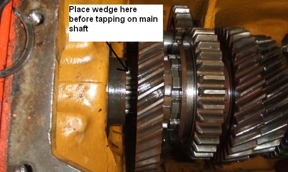

Edited by pre64 - 10 Jan 2012 at 6:53am
|
|
Coming up in the near future: another D17, 2-B's,WC styled, WC unstyled,2 snap coupler 3 bottom plows, pull type shredder,and 2 belly mowers.
|
|
pre64
Bronze Level
Joined: 04 Oct 2010
Location: Cable OH
Points: 34
|
Post Options
Thanks(0)
Quote Reply
Posted: 13 Jan 2012 at 9:08am |
D17 Transmission
Assembly Tools and Techniques
As promised I am adding a few pointers for assembly of this
project. Once you have received all your new gaskets, bearings, seals etc and
double checked to make sure they are right we will proceed.
You will find
that some of the gaskets come off very hard after the years. I still prefer
using a razor blade scraper to get down to the metal surfaces. You will notice
that some of the casting flaws will catch on your blades every now and then and
break your blades (make sure you have your safety glasses on for this) so make
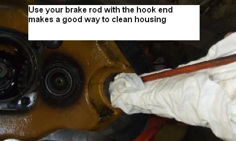
sure you have a handful of razor blades before you start. Once you have all of
your gaskets cleaned off, clean out all the junk from the housings and swab it
out good.
Now get
all your pinion and main shaft parts and gears ready to go. Here is a tip for
putting the pinion shaft in yourself . Get you a couple of feet of good wire
and put two bolts in your top transmission housing straight across from one
another near the front of the transmission. Wrap one side of the wire 2 or 3
turns around the bolt farthest from where you are standing and leave the other
end of it hanging. Get your pinion shaft and place it through your back housing
all the way to the bearing edge and hold onto the shaft with the other hand.
Now with one hand free start feeding your gears etc onto the shaft. Then in
order to free up your other hand grab your wire and loop under the front part
of the shaft and lift it up until it is nearly centered in the front housing
and give it a couple of wraps around the other bolt on the top housing. This
will temporarily hold it in place while you go to the rear and get your pinion
started up into the bearing housing. When you get ready to do your so called
“tapping” your shaft into the housing you will need a hard block or similar to
tap in the center of the pinion and drive into place. When you get within about
¾” or so from being into place, you will need to put on your “split ring”. I
usually grease them up good with some heavy grease so they will temporarily
stick into place and not fall out. Slide your retainer over the top of them
when done to hold it together. Don’t be afraid to put a wad of grease on this
as well to help hold it in place. Keep checking after each tap to make sure it
doesn’t come apart. Note; when tapping your shaft into place you will need to
keep slacking your wire that is holding the end of your shaft up. Once you have
started the pinion into that bearing housing I realize the shaft holds it self,
however the wire at this time serves to hold the gears from flying off the
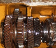
front of the shaft during the tapping process. This image is on the bottom
shaft assembly but the same technique is used on the top:
Once you
have your pinion and gears in place make sure your gears all turn freely and
each gear functions properly and is free. If your pinion shaft is binding at
all you probably drove it in a little to far. If this happens make sure you
have your snap ring on the front of the shaft and then give it a good tap
backwards and it should free right up. If all is well and you get your rear
bearing retainer plate on and all bolts tight, you will need about 18-20” of
steel wire .050” or less in diameter to put through the bolt heads as the
book indicates. End up with your splice for the wires where you have room to
work and about ½ way in the middle of two bolts. This will give you enough room
to twist the ends together. Once done clip off any excess and flatten all wire
down tight against the flange. This will prevent it from getting caught in your
ring gear.
With all of your parts cleaned good install all of your seals. When you are
installing the new orings, especially the ones on the rear axles bearing
holders, do not roll them into the grooves they fit in, but rather start one
side of it down into the groove and “carefully” stretch it just enough to get
the remainder of it into the groove. This will prevent the oring from twisting
that you get from rolling it into position. You want it to lay straight when it
is in the groove to prevent from catching during assembly, since it is a real
tight fit. Right before assembly put a little Vaseline on it all the way around
to help it go together.
When working alone and installing the ring gear assembly into the housing you
will need a couple of dowels, broom handles etc to fit though the axle housing
into the rear end to hold it up during assembly. Once you have it suspended
then you can get your bearing housing and shims and slide them over your
dowels, line it up and carefully push them into place. Make sure all of your
shims are lined up with the bolt holes during assembly. Don’t use the retainer
bolts to draw your bearing housing into place. If it is clean and lubed you
will be able to put them in by hand by turning them a little during assembly.
This will prevent you from pinching one of the orings. Once they are in place
tighten them up, Check now and insure it rotates freely and your ring gear and
pinion gap are good. If you have kept all of your shims straight on each side
it should go back to where it was. If you don’t have the dial indicators etc.
to check exact clearance make sure that there is a little play back and forth
between the ring gear and pinion. I would say no more than 1/8” back and forth
just as a guideline. When you are ready to install the rear axle housings I like to use the engine
hoist and put the strap as far out as it will go and it will be balanced then.
Make sure your brakes are spread clear apart and put a little grease on the
ends of the splines to help it to go together easier. Once you are lined up and
ready to start the axles into place, go easy and not bump the inner seals. If
you have it lined up it should go in a good ways and stop. At this point turn
your outer wheel hub a little back and forth and it should go all the way in.
Never draw it in with the bolts, it should always go together fairly easy by
hand. Also keep an eye that your don’t catch on your brake shoe linings going in.
Edited by pre64 - 14 Jan 2012 at 7:35am
|
|
Coming up in the near future: another D17, 2-B's,WC styled, WC unstyled,2 snap coupler 3 bottom plows, pull type shredder,and 2 belly mowers.
|
|
pre64
Bronze Level
Joined: 04 Oct 2010
Location: Cable OH
Points: 34
|
Post Options
Thanks(0)
Quote Reply
Posted: 14 Jan 2012 at 7:41am |
|
Finally got back to work on this yesterday. I now have the pinion shaft and all the gears and input shaft as well as the rear axles in place. I manually shifted all the gears into place one at a time and they all function properly now. Hope to have it back to together this weekend so I can move the tractor around and make some room.
|
|
Coming up in the near future: another D17, 2-B's,WC styled, WC unstyled,2 snap coupler 3 bottom plows, pull type shredder,and 2 belly mowers.
|
|
wjohn
Orange Level

Joined: 19 Jan 2010
Location: KS
Points: 2389
|
Post Options
Thanks(0)
Quote Reply
Posted: 14 Jan 2012 at 9:37am |
Awesome job, pre64! I haven't been into a tractor transmission yet and this write-up looks extremely helpful.
I really wish we had a "Stickies" section of the forum, so everyone could easily find this sort of thing later. Many members have done great write-ups like this that should be easy to find.
|
|
1939 B, 1940 B, 1941 WC, 1951 WD, 1952 CA, 1956 WD-45
|
|
pre64
Bronze Level
Joined: 04 Oct 2010
Location: Cable OH
Points: 34
|
Post Options
Thanks(0)
Quote Reply
Posted: 14 Jan 2012 at 11:52am |
It would be nice to be able to categorize some of the post on this forum so you could find them in the archives later, maybe by main categories: ie; engines, transmissions, clutches, electrical etc. and then break it down into sub categories even if it is broad for instance all D series tractors, W series or maybe even broader by years like 1930 to 1950 or whatever. This wouldn't need to be done for all post, but the ones that relate to specific areas of interest that would help a member solve a problem or do a specific task. At the same time I have ran several websites myself and know that it is very time consuming to make modifications etc. Especially for those that operate primarily on donations. As soon as I finish the final on this thread I plan on starting one to help others get motivated to make a donation and keep this great forum going. Breaks over....time to see if I can put two halves together and make a whole tractor again. More later... Tim
|
|
Coming up in the near future: another D17, 2-B's,WC styled, WC unstyled,2 snap coupler 3 bottom plows, pull type shredder,and 2 belly mowers.
|
|
pre64
Bronze Level
Joined: 04 Oct 2010
Location: Cable OH
Points: 34
|
Post Options
Thanks(0)
Quote Reply
Posted: 15 Jan 2012 at 8:11pm |
The tractor is back together now and everything works as it should. Other than a little more painting and some finishing touches it is done. Once it is all done I will post a final picture of it. I want to thank all that helped on this. This is a great forum! Not sure what will be next, but maybe another D17. It needs an engine over haul. Tim
|
|
Coming up in the near future: another D17, 2-B's,WC styled, WC unstyled,2 snap coupler 3 bottom plows, pull type shredder,and 2 belly mowers.
|
|


 Topic Options