| Author |
 Topic Search Topic Search  Topic Options Topic Options
|
calico190xt68 
Orange Level


Joined: 12 Jan 2017
Location: Frankton, IN
Points: 829
|
 Post Options Post Options
") Thanks(0) Thanks(0)
 Quote Quote  Reply Reply
 Topic: 7010 Hydraulic Leak Source Found Topic: 7010 Hydraulic Leak Source Found
Posted: 14 May 2022 at 5:12pm |
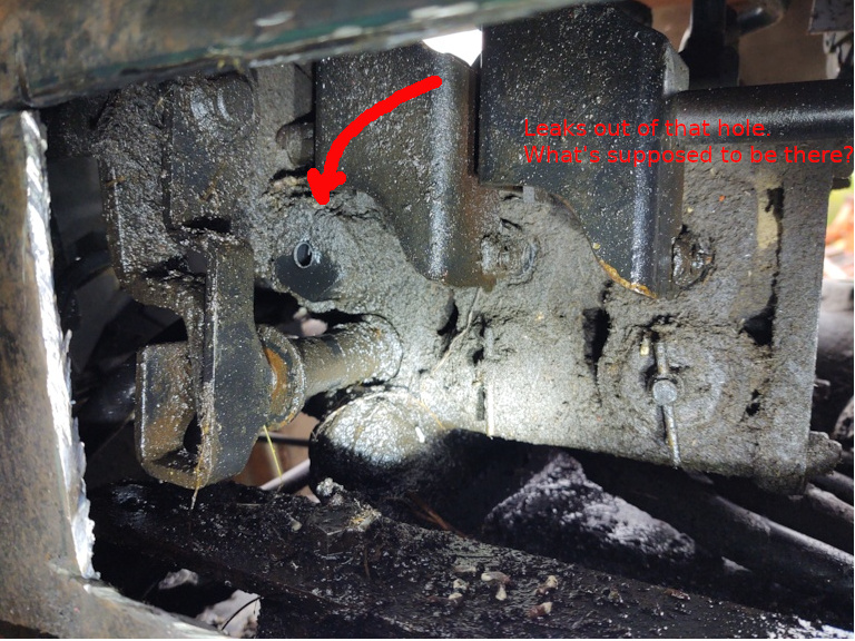
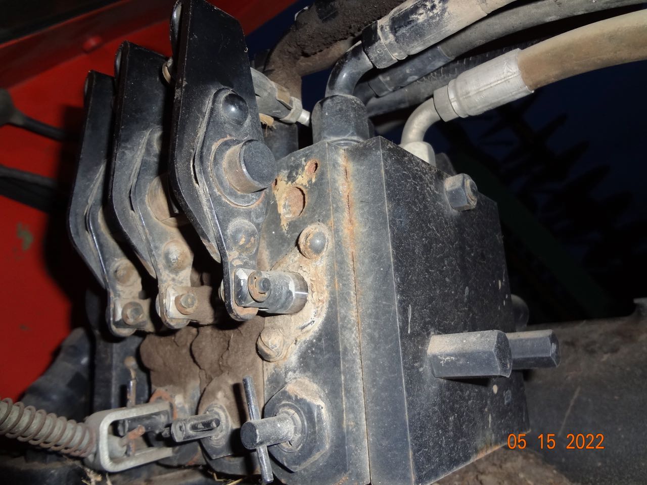
I posted quite awhile ago about my hydraulic leak that I thought I had on the number 1 remote. Turns out I was wrong. It turns out it is the Hydraulic Inlet valve. I have no idea how a hole developed in this cap (Part#) 70266875 . Maybe there is something missing. In order to discover the problem I resorted to cutting a hole in the cab as many suggested. I concluded there was no other way without lifting the cab from the tractor. So, I hope Agco has the cap. I see there are other parts to worry about once I remove that cap. I was going to replace the O ring while I am fixing the cap. Has anyone ever fixed this area? If so, any tricks to the process? Not a lot of room in there even with a new window. I also found that the flow control lever was not attached to anything when I went to cut that hole. Is that something that I need to worry about when I put back together? Not sure what it attaches to. Any help is appreciated. Tractor has become unusable with such a bad leak.

The hole is where the leak is.
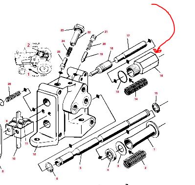
Here is parts diagram. It doesn't show anything but a cap? Does not show anything sticking out of that cap. How did it develop that hole, if nothing is supposed to be there?
|
|
80 7010, 80 7020. 67 190XTD Series I w/500 Loader, AC 2000 Plow, AC 4 row Planter, AC 77G Rake, Member Indiana A-C Partners, Member TAC
|
 |
|
Sponsored Links
|
|
|
Ron(AB)
Orange Level

Joined: 27 Dec 2009
Location: Alberta
Points: 959
|
Post Options
Thanks(0)
Quote Reply
Posted: 14 May 2022 at 6:54pm |
|
I'll see if I can get you a pic on mine.
|
|
405, 7000, 7050, 8050, 8070, L3, 2300 & 2600 disk
|
|
calico190xt68
Orange Level
Joined: 12 Jan 2017
Location: Frankton, IN
Points: 829
|
Post Options
Thanks(0)
Quote Reply
Posted: 14 May 2022 at 9:31pm |
That would be appreciated. Does that mean you have the cutout "window" that I have had to make? I know a few others have mentioned having this "option".
After studying the situation, I see only three options from what I know now. That cap is 1.5 inches across. I can't get a wrench on it without removing some things. I can't get a socket on it. I don't think I can even get a crowfoot on it but I don't have a 1.5 inch version.
Option 1: I am starting to believe that the reason the windows is cutout is to get a wrench on the bolt holding the hydraulic stack on to the rearend. There are 3 bolts holding the stack from what I can see. Two are accessible from the back. Now the third one is accessible from the window. There are 3 metal lines going into the stack that would have to be removed. The remotes are rubber hoses so easy to take off. The one thing that I do not know how to do and is not obvious is to take loose the bracket that holds the cables.
Option 2: Tap the hole with threads and screw a plug in?
Option 3: This might be a long shot and hard to do too, but I thought about putting epoxy in the hole, let it dry, then weld a 1 inch diameter flat metal to the end of the cap. This only makes sense if in fact there isn't something else that goes into that hole.
This is a tough fix for sure. You have to lay on your belly and you can't get a good view of the stuff under the cab on your belly. There is little to no room to do anything with wrenches.
Someone out there has had to fix this in the past.
|
|
80 7010, 80 7020. 67 190XTD Series I w/500 Loader, AC 2000 Plow, AC 4 row Planter, AC 77G Rake, Member Indiana A-C Partners, Member TAC
|
|
DougG
Orange Level
Joined: 20 Sep 2009
Location: Mo
Points: 8246
|
Post Options
Thanks(0)
Quote Reply
Posted: 15 May 2022 at 3:37am |
|
Thanks for the update
|
|
DrAllis
Orange Level Access
Joined: 12 Sep 2009
Points: 21361
|
Post Options
Thanks(0)
Quote Reply
Posted: 15 May 2022 at 6:14am |
|
Never seen a problem like yours. That hex cap never used to have a hole in the end. I would imagine if there is a round hole, there was some sort of a threaded plug in it. If I was working on this repair, the whole valve stack would have been removed or at least slide off each remote valve to the left and get them out of the way, which would then expose your problem part from the left side with the 3 point hitch fully down. A mirror would have found the leak. The hole in the cab still doesn't allow for a repair.
|
|
Play Farmer
Orange Level
Joined: 13 Jan 2016
Location: NNY
Points: 732
|
Post Options
Thanks(0)
Quote Reply
Posted: 15 May 2022 at 6:36am |
 calico190xt68 wrote: calico190xt68 wrote:
That would be appreciated. Does that mean you have the cutout "window" that I have had to make? I know a few others have mentioned having this "option".
After studying the situation, I see only three options from what I know now. That cap is 1.5 inches across. I can't get a wrench on it without removing some things. I can't get a socket on it. I don't think I can even get a crowfoot on it but I don't have a 1.5 inch version.
Option 1: I am starting to believe that the reason the windows is cutout is to get a wrench on the bolt holding the hydraulic stack on to the rearend. There are 3 bolts holding the stack from what I can see. Two are accessible from the back. Now the third one is accessible from the window. There are 3 metal lines going into the stack that would have to be removed. The remotes are rubber hoses so easy to take off. The one thing that I do not know how to do and is not obvious is to take loose the bracket that holds the cables.
Option 2: Tap the hole with threads and screw a plug in?
Option 3: This might be a long shot and hard to do too, but I thought about putting epoxy in the hole, let it dry, then weld a 1 inch diameter flat metal to the end of the cap. This only makes sense if in fact there isn't something else that goes into that hole.
This is a tough fix for sure. You have to lay on your belly and you can't get a good view of the stuff under the cab on your belly. There is little to no room to do anything with wrenches.
Someone out there has had to fix this in the past.
|
I was thinking option 2 makes sense.
|
|
calico190xt68
Orange Level
Joined: 12 Jan 2017
Location: Frankton, IN
Points: 829
|
Post Options
Thanks(0)
Quote Reply
Posted: 15 May 2022 at 7:53am |
I tried to get a mirror back there but I couldn't get a light or the mirror to shine just right to see what I had. Plus, I didn't really know what I was looking at. There was a lot of dirt and grime. I have cleaned it up since I took the picture. Now it is obvious so the window helped on that count. I think you would be hard pressed to get a wrench back there on the nut that holds the stack without the window, so I think it was inevitable. I will make it look as good as I can when I get some sheet metal to replace it.
I can't believe that the hole was somehow made by a break. It is too perfectly round so there must have been a plug in it and it came out. However, no parts diagram shows that plug either. If the hole wasn't there, then something from the inside would have had to poke it out. I don't see anything capable of doing that either. The up and down lift hydraulics work fine so there is no issue there.
At this stage, I think I am going to try and plug it. I actually thought about cutting off the sharp end of a self-tapping screw and putting sealant around it. It might not be leak proof but would greatly reduce the flow of fluid and buy me some time. It is literally running out in a pee stream now. I may be hard pressed to do a tap given the other stuff around it.
If that isn't possible, then removal of the stack is what will have to happen. Still don't know about the lever brackets and taking them loose, but will have to figure it out.
What about that flow control lever? If it doesn't get installed, is that a problem? I never adjusted it and it was not operational either.
Thanks everyone for the feedback. I wonder if anyone has a scrap
7000 series with no cab that could look at that area for me too?
|
|
80 7010, 80 7020. 67 190XTD Series I w/500 Loader, AC 2000 Plow, AC 4 row Planter, AC 77G Rake, Member Indiana A-C Partners, Member TAC
|
|
calico190xt68
Orange Level
Joined: 12 Jan 2017
Location: Frankton, IN
Points: 829
|
Post Options
Thanks(0)
Quote Reply
Posted: 15 May 2022 at 8:51am |
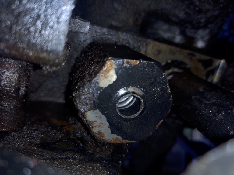
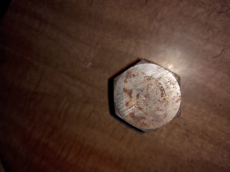
I have taken a closeup of the cap. This hole was definitely
drilled by the factory. It is very round and very thick. My micrometer
says it is about .36in diameter and I guess the hole is .375, if the outer lip weren't there. I put a wire into the hole until I
hit the spring and it was nearly 3/4 inch. Doesn't look that deep as you
can see the spring in the pic but deceiving.
On
the very outer edge of the hole it does look like something blew out
the plug. I don't see how the plug was held in place since there are no
threads inside. My guess is that the plug was assembled from inside
the cap and it must have had a lip. Not sure what would have sealed it
though. Maybe an O-Ring.
Looking at this
picture tapping would work. I hate to get shavings in there though. I
could tap a little and then suck it out with a shopvac as I go. Go in about 1/2 inch at
most. I have to cut a little more of the sheet metal away to get
straight in for a tap. Also the cap seems to be hard steel and thick so doubt a
self tapping screw would work for very long, if at all. I think the
pressure would blow it out.
Sure is weird mystery though why something like this was used. Let me know if anyone sees any other alternatives besides tapping at this point, or stack removal.
|
|
80 7010, 80 7020. 67 190XTD Series I w/500 Loader, AC 2000 Plow, AC 4 row Planter, AC 77G Rake, Member Indiana A-C Partners, Member TAC
|
|
Stan R
Orange Level Access
Joined: 03 Dec 2009
Location: MA
Points: 969
|
Post Options
Thanks(0)
Quote Reply
Posted: 15 May 2022 at 4:42pm |
|
I'm betting your source of leak is within the piston (actuator)/ o-ring system which is the "pressure side of the valve" and the spring/ cap (with the mysterious hole) is just some type of weep hole for any small leakage past the o-ring. The spring area is typically not in the high pressure zone of a valve.
|
|
calico190xt68
Orange Level
Joined: 12 Jan 2017
Location: Frankton, IN
Points: 829
|
Post Options
Thanks(0)
Quote Reply
Posted: 15 May 2022 at 5:46pm |
That would make more sense as to why there is a hole there and why it hasn't leaked before with the hole. Seems like the lift works fine but maybe it is weaker than I think. If the O-ring is leaking then my lift would creep down faster than normal, I think. If I plugged it, that would be a bad thing right?
Would be nice to know what one of those look like to see if they all have a weep hole. With Agco ordering in total disarray, it could take a week or more for me to get one. If I took the stack off, disasembled it all, I may have to guess at a similar O-ring if I can't get one quickly. That would also be hoping that nothing else is damaged.
Thanks for the idea. Would like to see one to know for sure if they all have a weep hole. Maybe I should just start taking the stack apart and remove so I can work on it as distasteful as that is. I will call Agco dealers and see what they have. I would think it would be a rare part to stock.
|
|
80 7010, 80 7020. 67 190XTD Series I w/500 Loader, AC 2000 Plow, AC 4 row Planter, AC 77G Rake, Member Indiana A-C Partners, Member TAC
|
|
Ron(AB)
Orange Level
Joined: 27 Dec 2009
Location: Alberta
Points: 959
|
Post Options
Thanks(0)
Quote Reply
Posted: 16 May 2022 at 12:24am |
|
|
|
405, 7000, 7050, 8050, 8070, L3, 2300 & 2600 disk
|
|
Bret (OH)
Silver Level

Joined: 15 Sep 2009
Location: Blanchester, OH
Points: 353
|
Post Options
Thanks(0)
Quote Reply
Posted: 16 May 2022 at 6:00am |
|
I would guess that there may have been a rubber plug in there just to keep out dirt. There should be no oil that is under pressure inside that cap, it is just a retainer for the internal spring. If oil is escaping through that hole it is coming from defective seals that are supposed to seal the spool inside the valve body. I would clean well and remove the cap and see if the seal or oring that seals the spool can be replaced without removing the stack. If you plug the hole so it is oil tight, the oil pressure will build to a point that the spool will not be free to move the way it is supposed to, and could cause other problems.
|
|
calico190xt68
Orange Level
Joined: 12 Jan 2017
Location: Frankton, IN
Points: 829
|
Post Options
Thanks(0)
Quote Reply
Posted: 16 May 2022 at 8:30am |
Ron(AB), big thanks for the pics. Based upon the 8000 series pictures, the flow control spring loaded knob attaches to the "T" adjustment that goes in that hole. I made mention that mine wasn't connected to anything when I cut the window. I noticed that the 8000 picture shows the spring loaded knob going in at an angle and my 7010 would be doing the same thing.
The parts book picture I posted above does not show anything from that angle to see the T. My guess is that the cap must come with those parts in it? I now don't believe it is a weep hole. There is a 7045 just down the road from me, so I am going to stop by and see if I can get a picture of what is behind there now that I know what I am looking for. Might get one of those cheap snake cameras from Harbor Freight to help me continue with this fix.
Regardless, of what I find, I think the cap has to come off. Looking at the parts diagram above, I believe the O-ring sits on the outside of the threads of the cap just to seal it. I don't see an internal O-ring from the diagram that could have failed.
My new guess is that T part provides some kind of seal. Pressure must have built up and pushed it out. When I look at the close up of the cap, it looks like the flange area around the hole is actually pushed out. It is not flush currently. I suspect that I will need a new cap regardless. I also wonder if the cap comes with the T pre-installed since it doesn't show those parts above.
So, now the mystery is what caused the flow control parts to fly out of the cap? If I replace the cap with the T will it happen again?
Bret(OH) brings up a good point on getting cap off. If I removed the brackets that hold the cables so that I can get a socket on the cap, I could remove it without taking the stack completely out. I don't yet know how easy that is going to be.
Since I have to take loose the bracket mount points even if I were to remove the stack, I believe the next step is to figure that out. If I can do that, I can make one of two choices, remove the cap or proceed with complete stack removal. If I removed the complete stack though, I could easily replace other O-rings in the valve bodies.
I need to find out more about the cap and what comes with it. So going to call Agco and see where that takes me once I see the 7045. I also don't really understand how that flow control knob works in relation to the valve body parts. I can see it twists about a half turn, left and right, but not sure how that works internally.
Thanks again for all of the help and ideas. This seems to be a very rare situation but I will continue to document, in case anyone ever deals with this again.
|
|
80 7010, 80 7020. 67 190XTD Series I w/500 Loader, AC 2000 Plow, AC 4 row Planter, AC 77G Rake, Member Indiana A-C Partners, Member TAC
|
|
DrAllis
Orange Level Access
Joined: 12 Sep 2009
Points: 21361
|
Post Options
Thanks(0)
Quote Reply
Posted: 16 May 2022 at 8:38am |
|
Leave the flow control's alone !!! Long side of the roll pin handle DOWN is 100% full flow. Long side of the roll pin straight up is minimum flow. Half-way (either way) is half flow. You can turn the flow controls in a circle, but long side down is 100% flow regardless of how many times you turn it in a circle.
|
|
calico190xt68
Orange Level
Joined: 12 Jan 2017
Location: Frankton, IN
Points: 829
|
Post Options
Thanks(0)
Quote Reply
Posted: 16 May 2022 at 9:22am |
|
I have no plans of changing flow control but if I get a new cap and T part then I may have to figure out where it currently stands and make sure I stall it correctly. With the T missing out of my cap, I don't know if it is left or right, full or half.
|
|
80 7010, 80 7020. 67 190XTD Series I w/500 Loader, AC 2000 Plow, AC 4 row Planter, AC 77G Rake, Member Indiana A-C Partners, Member TAC
|
|
DrAllis
Orange Level Access
Joined: 12 Sep 2009
Points: 21361
|
Post Options
Thanks(0)
Quote Reply
Posted: 16 May 2022 at 9:50am |
|
THERE IS NO "TEE" HANDLE ON THE CAP THAT HAS THE HOLE IN IT !! The tee handles are only for the remote valves, not the three point lift valve.
|
|
calico190xt68
Orange Level
Joined: 12 Jan 2017
Location: Frankton, IN
Points: 829
|
Post Options
Thanks(0)
Quote Reply
Posted: 16 May 2022 at 12:27pm |
I think i see where I have gotten off base regarding the T. Ron(AB) picture of 8000 series shows the flow control knob attached to one of his remotes and not his lift inlet. He has 3 remotes so I am not looking at his inlet. I have inlet and 2 remotes. Thanks for setting me straight on that.
I am going to call Agco and see if I can get a new cap or a picture of it. Maybe that will clear it up. If it is solid and does not have a hole, then I could plug the one I have.
I
|
|
80 7010, 80 7020. 67 190XTD Series I w/500 Loader, AC 2000 Plow, AC 4 row Planter, AC 77G Rake, Member Indiana A-C Partners, Member TAC
|
|
calico190xt68
Orange Level
Joined: 12 Jan 2017
Location: Frankton, IN
Points: 829
|
Post Options
Thanks(0)
Quote Reply
Posted: 16 May 2022 at 3:21pm |
|
Agco has the plug and the O-ring so we will see what I get on Thursday (Hopefully). Nothing was in stock to see a picture.
|
|
80 7010, 80 7020. 67 190XTD Series I w/500 Loader, AC 2000 Plow, AC 4 row Planter, AC 77G Rake, Member Indiana A-C Partners, Member TAC
|
|
calico190xt68
Orange Level
Joined: 12 Jan 2017
Location: Frankton, IN
Points: 829
|
Post Options
Thanks(0)
Quote Reply
Posted: 19 May 2022 at 8:08am |
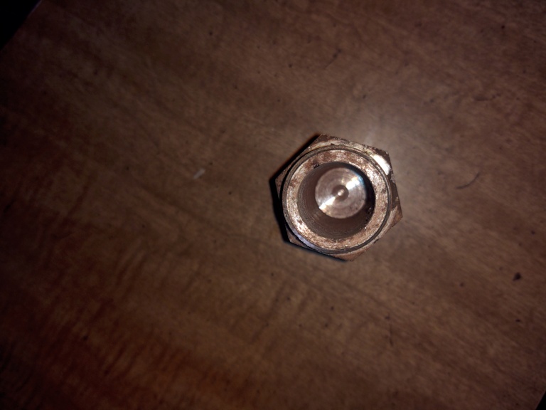
I got my Agco Cap as you can see below and it doesn't have a hole in it. Likewise, I measured the thickness of the cap end material and it is about 3/8 inch thick, so there is no way hydraulic issue would blow a hole out of it. I have no idea why my 7010 has a cap with a hole in it. Since mine has black paint on the interior of the hole it is clearly a factory hole. Must have had some kind of plug in it. Haven't looked down the road at the 7045 yet but I am expecting to see a similar cap to what I have bought.
I am trying to figure out how best to take the lever cage apart to get access to the cap. I think I can take the rod out from one end and remove lever push parts. I could get a socket on the cap if the one lever push part was removed. I have a long 3/4 extension that would protrude into the cab and should be able to break it loose from there.
I can still try to tap and plug the hole since it isn't supposed to have a hole if the cap installation becomes a problem. Trying not to de-install the entire stack. Still wet and raining so no significant loss of work yet but got to get it foxed soon.
|
|
80 7010, 80 7020. 67 190XTD Series I w/500 Loader, AC 2000 Plow, AC 4 row Planter, AC 77G Rake, Member Indiana A-C Partners, Member TAC
|
|
SteveM C/IL
Orange Level Access
Joined: 12 Sep 2009
Location: Shelbyville IL
Points: 8472
|
Post Options
Thanks(0)
Quote Reply
Posted: 19 May 2022 at 11:01am |
|
Hole or no hole something inside has to be leaking by so if you do nothing else you may cure the symptom but not the disease....may actually cause it to not work? You'll see.
|
|
calico190xt68
Orange Level
Joined: 12 Jan 2017
Location: Frankton, IN
Points: 829
|
Post Options
Thanks(0)
Quote Reply
Posted: 19 May 2022 at 12:06pm |
You raise the exact point I was considering last night. I have wondered about the leak based upon others implying that there should be no oil showing up in that area.
That would mean that other parts are worn and need replaced. On that upper chamber of the inlet where I have the leak, there aren't a lot of parts. I see there is a seal kit and an O-Ring on the front of the inlet block. I am guessing that would be where the leak is. I am guessing that if I took that cover off, these parts would be removal out of the cover area. I see the cover has a gasket so there must be oil flowing around that area.
The back parts from the diagram above where I have oil running out, don't show any O-rings. Not sure what happens if oil can't escape from that upper chamber. You would think there would be a good reason for the hole to be made by the factory.
I am new to repairing hydraulics and my main mechanic has torn his shoulder up and can't help me. As always, thank to forum members for jumping in. I will keep thinking about this some more.
|
|
80 7010, 80 7020. 67 190XTD Series I w/500 Loader, AC 2000 Plow, AC 4 row Planter, AC 77G Rake, Member Indiana A-C Partners, Member TAC
|
|
calico190xt68
Orange Level
Joined: 12 Jan 2017
Location: Frankton, IN
Points: 829
|
Post Options
Thanks(0)
Quote Reply
Posted: 19 May 2022 at 2:46pm |
|
I called Agco and they said the spring and the O-Ring are the only parts that have not been discontinued. The rest are not available and discontinued. It could be the O-ring though. Anyone taken that lift valve apart lately. Any guesses as to what is leaking?
|
|
80 7010, 80 7020. 67 190XTD Series I w/500 Loader, AC 2000 Plow, AC 4 row Planter, AC 77G Rake, Member Indiana A-C Partners, Member TAC
|
|
DrAllis
Orange Level Access
Joined: 12 Sep 2009
Points: 21361
|
Post Options
Thanks(0)
Quote Reply
Posted: 19 May 2022 at 8:43pm |
|
Replace that cap/plug with one that doesn't have a hole in it and your leak is fixed. There should be oil in there. Why does it have a hole in it ?? I have no idea, but I do know without a hole there is no more oil leak !!
|
|
calico190xt68
Orange Level
Joined: 12 Jan 2017
Location: Frankton, IN
Points: 829
|
Post Options
Thanks(0)
Quote Reply
Posted: 20 May 2022 at 9:29am |
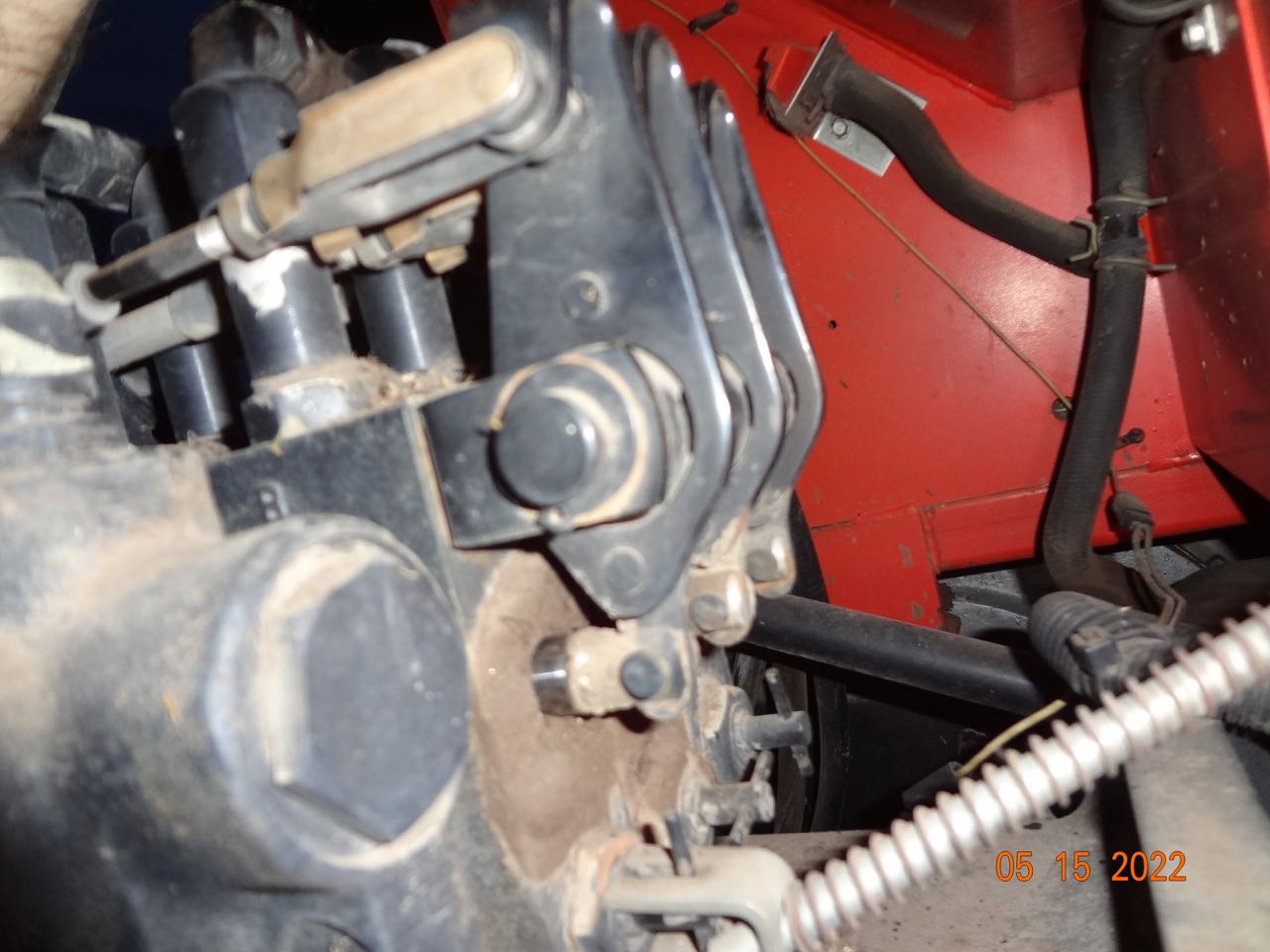
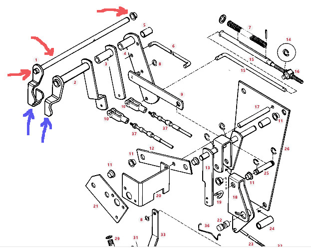
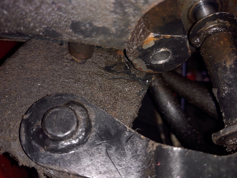
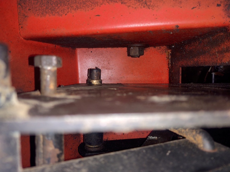
The key to me removing the cap plug is to remove the solid rod
that links all of the controls together. My arrows in red show what I
need to remove. On the left end, it appears to be welded to the
bracket. On the other end, there appears to be a ring crimped
onto the rod? It might be brass? Regardless, both ends look near impossible to remove. Assuming that I can't easily remove the rod, I have to do something else.
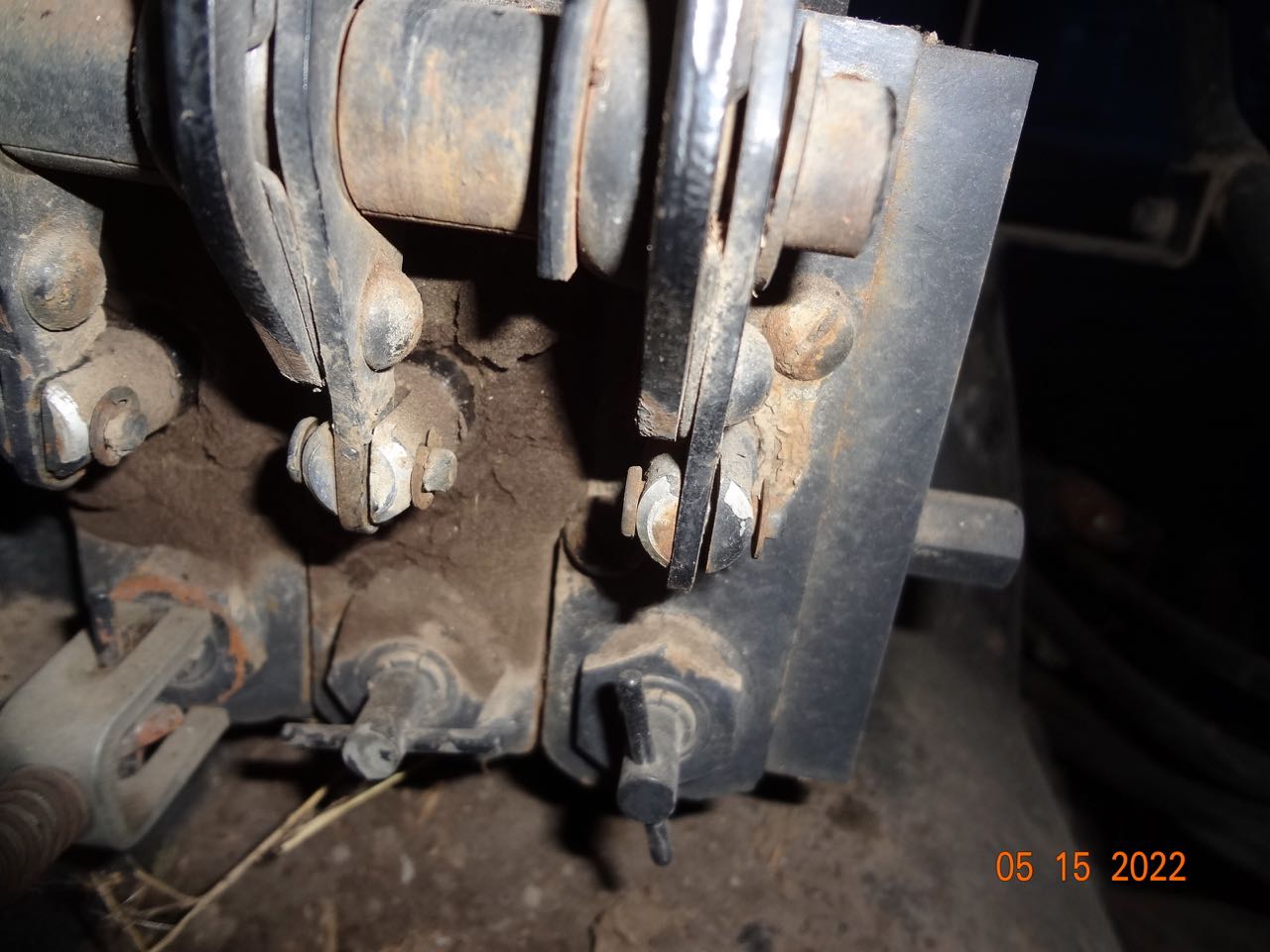
If you look at the parts diagram, there seems to be a small hole in the middle of the rod which is part #1 below. There is also a hole in the right remote push bracket which is part #3 below. I can't see it right now due to other things in the way, but my guess is there is a pin holding the rod stationary to the remote bracket. Without that pin, the rod would rotate 360 degrees. I need to find that pin and remove. That would allow the welded end to rotate upward. I could then take loose the left remote bracket from the cable. This would let that bracket rotate upward and out of the way, maybe. With both of those brackets, out of the way, I can get a socket on it. I also cannot tap the hole because these same brackets are in the way so that idea is out.
When
you look at the parts diagram below, it shows some kind of cap looking part
but it doesn't have a part number. Parts diagram doesn't show a key either. Those two metal
push parts pointed to by blue arrows have to be moved out or upwards 1.5 inches so I
can get a socket on that cap.
I have taken the
whole right side of the bracket loose, but that rod connects it all
together and doesn't help.
If I can figure this out, I am home free on replacing the
cap but this is a tough one. Everything I am doing is by feel and a camera. You can't see anything under there. I am suspecting this is a rare fix since no one is chiming in on removal.
See pictures below to see what I am dealing with.
Here is the left end of rod underneath cab.
Here is the right end with the ring holding the rod in place. Picture almost looks like it has a key way but could be the shadow.
|
|
80 7010, 80 7020. 67 190XTD Series I w/500 Loader, AC 2000 Plow, AC 4 row Planter, AC 77G Rake, Member Indiana A-C Partners, Member TAC
|
|
calico190xt68
Orange Level
Joined: 12 Jan 2017
Location: Frankton, IN
Points: 829
|
Post Options
Thanks(0)
Quote Reply
Posted: 20 May 2022 at 9:39am |
|
I need to correct myself. That isn't the remote cable push bracket but rather the lift cable actuator that I need to remove from the bracket to allow rotation.
|
|
80 7010, 80 7020. 67 190XTD Series I w/500 Loader, AC 2000 Plow, AC 4 row Planter, AC 77G Rake, Member Indiana A-C Partners, Member TAC
|
|
DrAllis
Orange Level Access
Joined: 12 Sep 2009
Points: 21361
|
Post Options
Thanks(0)
Quote Reply
Posted: 20 May 2022 at 9:49am |
|
There are two bolts holding p/n 20 & 21 to the side of the 3pt valve. Remove them and the two big bolts down on the right real axle final drive and that whole assembly is loose and could be moved around away from where you want to work. The rear of the cab could be raised 3 inches fairly easily to create even more room.
|
|
calico190xt68
Orange Level
Joined: 12 Jan 2017
Location: Frankton, IN
Points: 829
|
Post Options
Thanks(0)
Quote Reply
Posted: 20 May 2022 at 10:30am |
I have the two big bolts removed on the right rear axle. I will attempt to find the two bolts that you mention and get them removed. I didn't see them but I might need to clean more dirt grime off.
Be really good to not remove that shaft but just shift over the control brackets!
I did look at the possibility of raising the cab to get me some room. Could you describe what is involved in raising the cab? I see the two big bolts in the rear and I saw some in the cab floor when I was fixing the shift cables. What steps are necessary if I end up there? Sometimes I think the effort to raising the cab might be better than working blind.
Thanks for the hint! I want to get this over with.
|
|
80 7010, 80 7020. 67 190XTD Series I w/500 Loader, AC 2000 Plow, AC 4 row Planter, AC 77G Rake, Member Indiana A-C Partners, Member TAC
|
|
MACK
Orange Level
Joined: 17 Nov 2009
Points: 7664
|
Post Options
Thanks(0)
Quote Reply
Posted: 20 May 2022 at 9:11pm |
|
Back of cab can be raised real easy. Unbolt from axel, lay 2x4 under back edge of cab, use small bottle jack under 2x4 to lift cab. MACK
|
|
calico190xt68
Orange Level
Joined: 12 Jan 2017
Location: Frankton, IN
Points: 829
|
Post Options
Thanks(0)
Quote Reply
Posted: 21 May 2022 at 7:52am |
I have had success on fixing this leak! A big thanks to DrAllis for the hints on taking the hydraulic lever assembly loose. I did not have to raise the cab after all, but thanks for the hints on that. After having done this job, I think it is possible to do it without cutting the cab "window" that I cut, but it got done. I also couldn't visualize the leak until I cut the window. I think my problem is rare since the cap isn't supposed to have a hole in it. I think raising the cab 3 inches would be wise if the window isn't cut.
I raised and lowered the lift many times and I see no problems yet. Will be working the tractor as soon as the weather cooperates so the jury is out until then.
Just so I can save the next guy the anguish I faced, here is complete breakdown of the steps to fix my problem. I bought an inspection camera that also helped me after I cut the window. I should have bought that first and i would have known where the leak was. Here are the sordid details on loosening the lever assembly.
Steps to take loose the lever assembly
under the 7000 series cab.
Loosen the two large bolts that
attach to the tractor rear end frame using 15/16 socket. These
bolts cannot be removed after loosening as they hit the cab frame.
Remove the two metal rod linkages
going to the traction booster and the lift. There are two cotter
pins that can be pried downward to pull out. Area is very tight so
use long needle nose pliers.
Loosen the top bolt by using a box
end wrench on the nut and a 9/16 socket on the right. Once the nut
is removed pull the bolt out of the frame. This bolt cannot be
removed as it hits the tractor cab.
Now that half of the lever
assembly is loose, the loose section can be pushed downward and
forward to get one of the lower big bolts out. Once the back bolt
comes out, the frame can be pushed forward and the front bolt can
come out.
Part 20 from the lever assembly
diagram needs to be removed next. There are two ½ inch bolts
holding that flat bracket onto the stack. I had to loosen the small
hydraulic line and push down to get my socket on the other side of
the bracket. You have to fish the socket wrench under the bracket
for the top bolt. You are doing this all by feel as you cannot see
what you are doing.
The bottom bolt required the use
of a swivel socket adapter. I had to go about two clicks at a time
until it loosened. Once loosened leave it alone and come back to it
after removing the 9/16 bolt at the top of the bracket.
9/16 bolt and nut holds the #20
part to the #21 part in parts diagram. Once this is removed, the
whole assembly is free except for the remote brackets. I was
looking to shift the lever assembly over about an inch so I was
done.
If you were going to remove the
hydraulic stack to fix something on the back, you would have to
remove the top 4 bolts on the remote brackets. This would
completely make the lever assembly free of the stack.
I never figured out how to remove
the rod that holds everything together but I don't think it wold be
necessary unless something buggered up the lever assembly intself.
If you wanted to remove the stack
at this stage, I think you can take loose all of the lines and the 3
bolts that hold the entire stack together and remove as one piece, I
think. There is a nut on the back side of the stack that has to be
removed. Once the lever assembly has been loosened, you could get a
sock with extension on that nut and remove. You will be working
blind though doing it.
Since I had cut a window hole in
my cab, all of this was accessible and easy to see. Without the
window, the back side nut is tough to get loose.
My goal was to remove the
mysterious cap that had a hole in it and was leaking hydraulic oil. After loosening the lever assembly, I could get a 1 ¼ socket on
the cap. I had a 12 inch extension that protruded into the cab and
I easily loosened the cap from inside the cab.
To do this I really didn't need
such a large window. I could have cut a window about 3 inches
square towards the left of the left seat bracket towards the top of
the sheet metal where it curves downward as you are looking at the
seat bracket. I ended up cutting a 10 inch window since I didn't
know where the leak was.
Removal of the end cap requires
you to carefully pull out cap plus 2 parts, making sure you capture the spring and the
metal rod as you pull it out. Spring isn't under pressure but you
don't want to drop either of them in that area and have to fish them
out.
After installing the new end cap
(with no hole), I had to do one special step. When re-installing
the part #21, you want to screw in the lower nut without part #20
and also tighten the screw that holds Part #21 to the hydro stack.
This is done to insure that part #20 will line up once you start
putting bolts back in it. Since you are working by feel and blind,
this is necessary. Prior to installing, part #20, you will remove
the lower bolt. The other bolt will hold the lever assembly into
place after you remove the lower bolt.
Everything else goes back in
reverse order. Make sure that you place the big lower bolts into
their position loose before you start to tighten up everything on
top..
As always, thanks for the help from everyone who chimed in. I know I saved some big dollars doing this fix myself, with forum help.
|
|
80 7010, 80 7020. 67 190XTD Series I w/500 Loader, AC 2000 Plow, AC 4 row Planter, AC 77G Rake, Member Indiana A-C Partners, Member TAC
|
|