| Author |
 Topic Search Topic Search  Topic Options Topic Options
|
calico190xt68 
Orange Level


Joined: 12 Jan 2017
Location: Frankton, IN
Points: 902
|
 Post Options Post Options
") Thanks(0) Thanks(0)
 Quote Quote  Reply Reply
 Topic: 190xt - Joystick Addition Problem Topic: 190xt - Joystick Addition Problem
Posted: 23 Apr 2022 at 4:14pm |
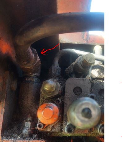
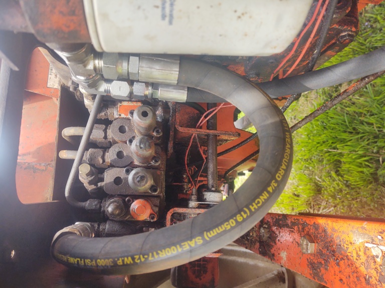
I am attempting to remove the metal hydraulic line that goes out of the hydraulic stack and into the Hydraulic Filter. I want to place a T adapter for my return hydraulic line coming out of the joystick right before the hydraulic filter. Unfortunately, there is little to no room to put a wrench on the nut to remove the steel hydraulic line. Anyone have any hints on how to loosen that nut? My 1 1/4 inch wrench has no room to move before it hits the detent and it can only go in there one way. I thought about ordering a crowfoot wrnech as my next plan if no one has any better ideas. Thanks for any help. See pictures below.
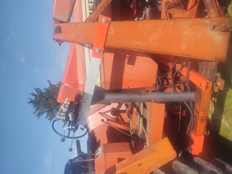
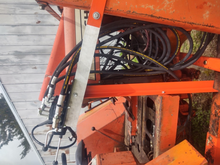
Here is the joystick mount. Joystick control weighs 40 lbs so I had to use some c channel aluminum and angle iron to support it. I just need to get the hoses run now but the above problem is stopping any further progress.
|
|
80 7010, 80 7020, 68 190XTD, 67 190XTD, 500 Loader, AC 2000 Plow, Member Indiana A-C Partners, Member TAC
|
 |
|
Sponsored Links
|
|
|
DrAllis
Orange Level Access
Joined: 12 Sep 2009
Points: 22685
|
Post Options
Thanks(0)
Quote Reply
Posted: 23 Apr 2022 at 4:35pm |
|
Remove the line from the filter base to the sump (will require draining the oil ) and have someone weld/braze a pipe coupling to it and then connect your return.
|
|
DanWi
Orange Level Access

Joined: 18 Sep 2009
Location: wttn
Points: 2050
|
Post Options
Thanks(0)
Quote Reply
Posted: 23 Apr 2022 at 6:05pm |
|
Without studying the picture I have found a 90 degree wrench works better on some spots or a short stubby wrench. It get a cheap wrench and modify to fit.
|
|
DiyDave
Orange Level Access

Joined: 11 Sep 2009
Location: Gambrills, MD
Points: 55089
|
Post Options
Thanks(0)
Quote Reply
Posted: 23 Apr 2022 at 6:57pm |
HF pump wrenches:
Or as others have said, cut up, bend or butcher a cheap wrench. Or find a set of 4 way wrenches...
I am not endorsing HF. They are just the easiest to find. 4 way angled wrenches are made to turn bolts in obstructed areas, each flip of the wrench moves the bolt, nut or line just a little, hence the term flippin wrenches...  |
|
Source: Babylon Bee. Sponsored by BRAWNDO, its got what you need!
|
|
jngeorge
Bronze Level


Joined: 08 Sep 2010
Location: S. Coffeyville
Points: 18
|
Post Options
Thanks(0)
Quote Reply
Posted: 23 Apr 2022 at 6:58pm |
|
Doing the same today. Started to add some photos but file is too large? Idk.
Anyway I was thing about just tapping into the drain plug just under were that drain line goes into the tractor. Is there anything wrong with that? Should be really easy. Zip tie the line to the drain line to keep it secure. I am using the same valve body you have pictured also.
I’m trying to decide where to tie the pressure line into and the power beyond.
Looking at the pump I have 4 lines coming off. 1 going to the oil cooler and I know that’s not the one I need. A 1/2 line come nag out of the back of the pump going to looks like the pto with a T under the dash for the power steering. Also have a 5/8 line out of the top of the pump towards the rear going to one side of my hydraulic controls and then a 3/8 line out the top of the pump closer to the front going to the other side of my hydraulic control valves close to the return line back to the sump. That line also has a t under the dash that is capped off. I little guidance would be appreciated. Thanks everyone!
|
|
Joe(TX)
Orange Level

Joined: 11 Sep 2009
Location: Weatherford. TX
Points: 1682
|
Post Options
Thanks(0)
Quote Reply
Posted: 23 Apr 2022 at 7:35pm |
You need a wrench made for flare nuts. You won't find one at Harbor Freight of that size. A 1 1/4 box end with a 3/4 slot but in it might work.
|
|
1970 190XT, 1973 200, 1962 D-19 Diesel, 1979 7010, 1957 WD45, 1950 WD, 1961 D17, Speed Patrol, D14, All crop 66 big bin, 180 diesel, 1970 170 diesel, FP80 forklift. Gleaner A
|
|
jngeorge
Bronze Level
Joined: 08 Sep 2010
Location: S. Coffeyville
Points: 18
|
Post Options
Thanks(0)
Quote Reply
Posted: 23 Apr 2022 at 9:20pm |
|
I didn’t mean to try and hi-Jack this post. I got my problem solved. Plumbed into the 5/8 line from the pump. Went to the inlet of the new valve and the PBY port and went back to where I cut the 5/8 line and fed it like it originally was. Added the dump hose to the drain plug. By going to the plug I am skipping the filter though.
|
|
calico190xt68
Orange Level
Joined: 12 Jan 2017
Location: Frankton, IN
Points: 902
|
Post Options
Thanks(0)
Quote Reply
Posted: 23 Apr 2022 at 9:43pm |
There is a lot going on here.
First, I think joe(tx) suggestion on the open ended flare nut wrench is the cats meow. $73 plus shipping is probably a good idea. I jumped the gun and bought a cheap crowfoot on Amazon. John Deere guys use them a bunch. We will see. Otherwise, I will go back to the flare nut wrench. Thanks for that!
jnjorge, regarding the pictures. I use an android phone and Aquamail as an email program. When I send a picture to myself, it asks me if I want to reduce it. I pick the lowest setting and I can load the pic to the forum site. If you have an iphone, not sure but there has to be something equivalent.
Regarding the overall plan, I saw a diagram on this site on how to tap into the hydraulics and it showed putting the T behind the filter so that's why I started there. That way the fluid always gets filtered, I think? I am hesitant to go and modify that tube in front of the filter. I don't know anyone that can splice that metal line and what if they screw it up? My plan was to buy a small rubber hose and put that into the stack opening then screw into the T. That should be easy in theory. :-)
Regarding the tap into the pressure side, I believe that 5/8 union is the place to do it from the diagram. I haven't got there yet, but I believe that is the only location to make this work. Once I get this T in place, that is my next step. Again, according to the diagram you break that union, put a 90 degree fitting into the Princeton In port and the other 90 degree goes to the Power Beyond port on the Princeton Joystick. I had to buy a special Power Beyond fitting for the Princeton Joystick at $28. As soon as I get done with the T, I will post pics for the rest of the mods.
I have never done this but I believe this can be done. My only concern is that my hydraulic pump might be weak and not do what I want. I did notice that there is some hydraulic fluid around the stack. My guess is that the o-rings have failed and my pressure may not be what I need to use the joystick/grapple. As always, 1 step forward and maybe two steps backward. Thanks to all for the help and suggestions.
|
|
80 7010, 80 7020, 68 190XTD, 67 190XTD, 500 Loader, AC 2000 Plow, Member Indiana A-C Partners, Member TAC
|
|
calico190xt68
Orange Level
Joined: 12 Jan 2017
Location: Frankton, IN
Points: 902
|
Post Options
Thanks(0)
Quote Reply
Posted: 23 Apr 2022 at 9:48pm |
|
Jnjorge, I didn't see your post until now as I was writing mine. No worries on the hijack. Funny you were working on the same thing on the same day. That is good news you got it working! I don't know for sure about skipping the filter. I will keep all posted on my progress.
|
|
80 7010, 80 7020, 68 190XTD, 67 190XTD, 500 Loader, AC 2000 Plow, Member Indiana A-C Partners, Member TAC
|
|
farmboy520
Orange Level Access
Joined: 22 Jun 2016
Location: Beason, IL
Points: 553
|
Post Options
Thanks(0)
Quote Reply
Posted: 25 Apr 2022 at 12:47pm |
|
You could make your own wrench using a box end combination wrench and cut a section out with a chop saw.
|
|
On the farm: Agco Allis 9695, 7060, 7010, R66, Farmall H, and Farmall F20 (Great Grandpa's)
|
|
calico190xt68
Orange Level
Joined: 12 Jan 2017
Location: Frankton, IN
Points: 902
|
Post Options
Thanks(0)
Quote Reply
Posted: 25 Apr 2022 at 2:58pm |
Thanks for the suggestion on making my own. I did in fact cut my wrench in half and it fit under the cab floor then and I was able to get the fitting loose. Didn't really want to pay $63 for that wrench.
One of the things that is tough about this joystick is related to the fittings sizes. When I break the union of the hydraulic line coming out of the pump, that is a 3/8 inch or SAE 6 fitting and my input on the joystick is a 3/4 or SAE 12. You can't go from a 6 to a 12. So, I have a SAE 6 JIC elbow with a SAE 6 to SAE 8 convertor, then going into the joystick I have a JIC 12 to JIC 8 elbow. They were out of the SAE 6 to 8 Elbows so I had to buy an extra convertor. This means I am using an SAE 8 hose.
Going out of the joystick into my hydraulic lines on the loader, I am using JIC 10 fittings and lines which are much bigger than needed. I don't see any other way to do this. The return line out of the joystick will be a SAE 12 to SAE 12. The Power Beyond Port is also SAE 12. I know this joystick is rated for 25GPM equipment and I am only pushing 11GPM so that probably accounts for the oversized ports for my application. Fittings and hoses got expensive for this project as I am up to about $500 and not completely done. JoyStick was $500. For some reason, Surplus Center is out of nearly all SAE 12 hoses so I am glad I didn't need very many. I am curious what jngeorge did on all of his fittings? I will document all that I used to avoid someone else buying too many fittings (like I did). I might be done with this project by this coming weekend with luck.
|
|
80 7010, 80 7020, 68 190XTD, 67 190XTD, 500 Loader, AC 2000 Plow, Member Indiana A-C Partners, Member TAC
|
|
Joe(TX)
Orange Level
Joined: 11 Sep 2009
Location: Weatherford. TX
Points: 1682
|
Post Options
Thanks(0)
Quote Reply
Posted: 25 Apr 2022 at 3:04pm |
You probably saw the crude diagram I posted a few years ago. It is not critical to return through the filter since it only has flow when the loader valve is operated. I did so because I wanted all oil filtered. The steering and power director oil is not filtered. Using a hose between the valve and filter would be ok. You would need something like a JIC/ORB run tee at the filter.
|
|
1970 190XT, 1973 200, 1962 D-19 Diesel, 1979 7010, 1957 WD45, 1950 WD, 1961 D17, Speed Patrol, D14, All crop 66 big bin, 180 diesel, 1970 170 diesel, FP80 forklift. Gleaner A
|
|
calico190xt68
Orange Level
Joined: 12 Jan 2017
Location: Frankton, IN
Points: 902
|
Post Options
Thanks(0)
Quote Reply
Posted: 25 Apr 2022 at 3:33pm |
|
joe(tx) Thanks for that knowledge. I am still going down the path to connect up a T with SAE 12 JIC male and SAE 12 JIC Female and then another JIC 12 male to filter all oil. I just don't know how I am going to bend the connecting hose around in that cramped space to replace that metal tube. I got a 2 foot piece of 12 SAE hose coming so hopefully I can get it connected. A 12 hose is very stiff.
|
|
80 7010, 80 7020, 68 190XTD, 67 190XTD, 500 Loader, AC 2000 Plow, Member Indiana A-C Partners, Member TAC
|
|
calico190xt68
Orange Level
Joined: 12 Jan 2017
Location: Frankton, IN
Points: 902
|
Post Options
Thanks(0)
Quote Reply
Posted: 01 May 2022 at 12:29pm |
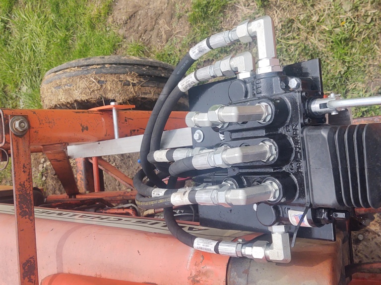
I finally finished this install. First few pictures were the tricky part that I wasn't sure about originally. I ended up getting a 3/4 T (SAE 12) and connected it to the filter. I ended up getting a 2 ft SAE 12 Hose and you can see I had to loop it. I couldn't find a 1 ft hose in stock and I think that would have been best. I ended up putting an adapter moving the 12 to a 10 size and ran a 10 hose to the output port on the joystick. The joystick had all 12 SAE ports. Due to parts availability I had to get reducers rather than buy an elbow that went from 12 to 10. I am going to try and make a video of all of the issues to watch out for.
The only problem I have encountered is that the up movement of the boom is slower than when I was using the remotes. Not sure why? Should I be using a smaller diameter hose going into the controller? Princeton manual didn't mention anyway to change the speed. Slow isn't the end of the world. It may be safer in some ways.
I have not run the hoses for the bale grabber yet. I wanted to install it and make sure I know how long the hoses need to be before I buy.
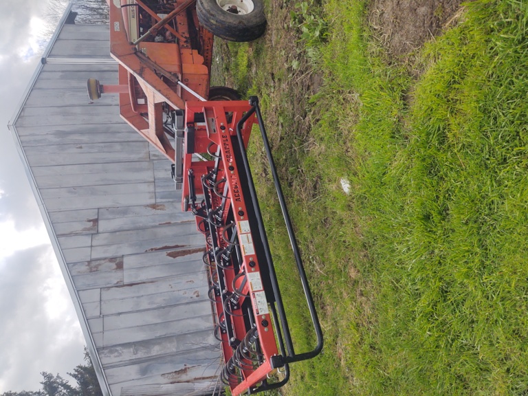
For those that want to tackle this and wondering on cost, I have $485 into the controller, I have about another $600 in fittings and hoses. Not to mention the Skidsteer Universal adapter, skidsteer bucket, skidsteer bale spear, skidsteer bale grabber and skidsteer hay grapple. About double what I have invested in the tractor! All parts were bought from Surplus Center. I will say it is really convenient and fast to switch from one implement to the other. I bought a smaller 5 ft bucket because I feel that the 500 loader matches a 5ft bucket. That's what I took off of it.
Enjoy the pics and now I have to get my Allis Plow ready!
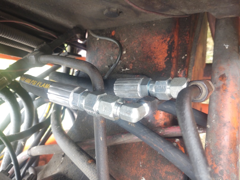
This picture shows where I split the hydraulic line coming out of the pump. I used SAE 6 Elbow, then converted to SAE 8 for the hose. At the controller, I went from the pump to the IN port. The other line is going to the Power Beyond port.
Here is the OUT port hose from the controller on the end of the T, the other T port going down goes back to the hydraulic stack. I show two shots of this area under the platform.
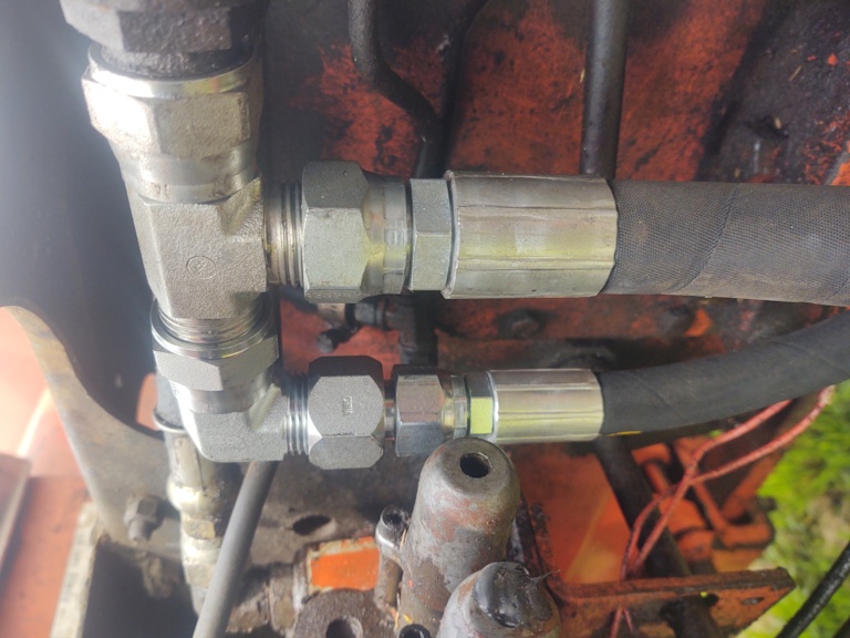
This shows the mount and fittings. I got short and extra long elbows so that the lines will fit on top of each other and around each other. The plate is 12 inches by 12 inches. I almost made it too close to the tractor but got lucky.
Here is side view. I think I have enough droop on the lines to install the side panels, but will find out soon.
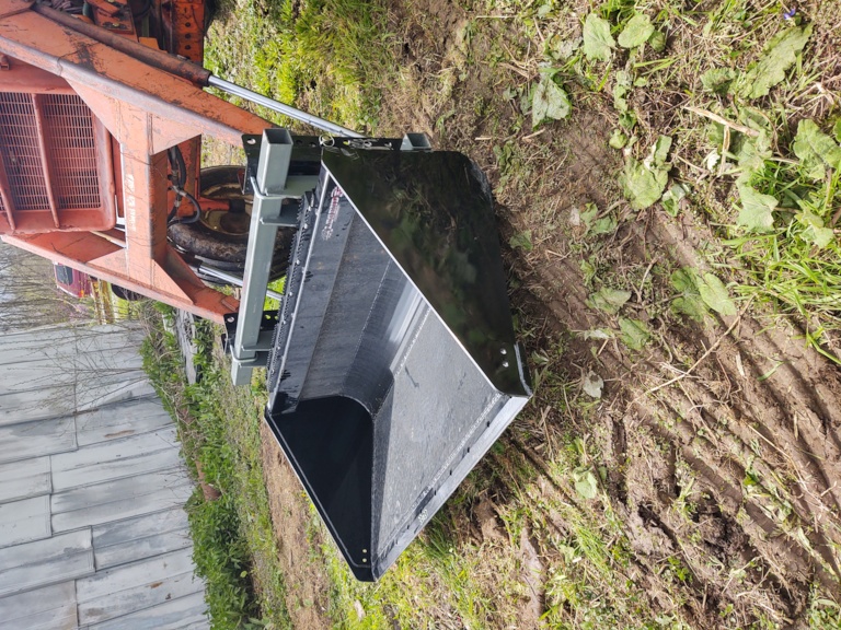
Here is the bucket pic and hay grapple pic.
|
|
80 7010, 80 7020, 68 190XTD, 67 190XTD, 500 Loader, AC 2000 Plow, Member Indiana A-C Partners, Member TAC
|
|
Joe(TX)
Orange Level
Joined: 11 Sep 2009
Location: Weatherford. TX
Points: 1682
|
Post Options
Thanks(0)
Quote Reply
Posted: 01 May 2022 at 2:59pm |
|
I mounted my valve to the instrument/steering casting. I drilled and tapped 2 holes to mount the bracket. That way I can remove the loader without disconnecting the pressure etc holes.
|
|
1970 190XT, 1973 200, 1962 D-19 Diesel, 1979 7010, 1957 WD45, 1950 WD, 1961 D17, Speed Patrol, D14, All crop 66 big bin, 180 diesel, 1970 170 diesel, FP80 forklift. Gleaner A
|
|
calico190xt68
Orange Level
Joined: 12 Jan 2017
Location: Frankton, IN
Points: 902
|
Post Options
Thanks(0)
Quote Reply
Posted: 01 May 2022 at 3:23pm |
I don't envision taking this loader off except if something breaks or I paint it, so would be rare. However, you bring up a good point. In my case, the vertical angle iron would support the valve. While the vertical angle iron is resting on the loader arm, I also have a bolt going through it to the platform that could support the valve if the loader was gone. Assuming I took the two clamp bolts off the loader frame to release the valve body from the loader, I could add an angle brace to one of those holes to support the valve in two places with the loader missing. I have quick disconnects in the middle of the 4 hoses going to the loader cylinders so they would be disconnected easily. With the addition of an angle brace I should be able to accomplish what you did.
The little things matter so glad you pointed that out. I got a plan in case it does have to come off without undoing a bunch of hoses.
I will be curious if anyone has any answers on how to speed up the raise on the boom. Did that slowness happen to you?
|
|
80 7010, 80 7020, 68 190XTD, 67 190XTD, 500 Loader, AC 2000 Plow, Member Indiana A-C Partners, Member TAC
|
|