| Author |
 Topic Search Topic Search  Topic Options Topic Options
|
Pippin5267 
Bronze Level


Joined: 16 Jul 2010
Location: Bristol, TN
Points: 15
|
 Post Options Post Options
") Thanks(0) Thanks(0)
 Quote Quote  Reply Reply
 Topic: 12 volt conversion problems Topic: 12 volt conversion problems
Posted: 22 Jul 2010 at 9:15pm |
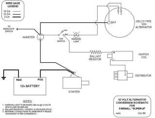
I did a 12 volt conversion on my wd45 this week and when I tried it out today everything worked fine except for the tractor would not quit running when the ignition swith was turned off. I wired in a diode just like I was told. It was a 50 amp diode in the wire between the the ignition switch and the internal voltage regulator on the alternator. I know I had the cathode turned the right way too because I tried it both ways. If anyone could help me with this problem I would greatly appreciate it. Thanks.
This is how my tractor is currently wired. As i said above I used a dioe instead of the warning light.
|
 |
|
Sponsored Links
|
|
|
Brian Jasper co. Ia
Orange Level

Joined: 11 Sep 2009
Location: Prairie City Ia
Points: 10508
|
Post Options
Thanks(0)
Quote Reply
Posted: 22 Jul 2010 at 9:33pm |
Where did you get that schematic? I'm pretty sure the wires on the alternator are backwards. Switch them around and see what happens.
|
|
"Any man who thinks he can be happy and prosperous by letting the government take care of him better take a closer look at the American Indian." Henry Ford
|
|
dadsdozerhd5b
Orange Level

Joined: 27 Sep 2009
Location: lansdale pa.
Points: 527
|
Post Options
Thanks(0)
Quote Reply
Posted: 22 Jul 2010 at 9:51pm |
|
unless the you have the terminals mixed up on the ign. switch. the voltage has to be coming from the alt. disconnect the lead from the alt. and see if it still does it. i think you can get away with not hooking up that wire off of the alt. as it is excited by the wire hooked to the bat. the light was to tell if it was charging or not. hopes this makes sense.
|
|
HD5B, HD5G, (2) FARMALL A's, CUB. DO IT RIGHT THE FIRST TIME, IGNORE THE LAUGHTER. FLANNEL IS ALWAYS IN STYLE.
|
|
Brian Jasper co. Ia
Orange Level
Joined: 11 Sep 2009
Location: Prairie City Ia
Points: 10508
|
Post Options
Thanks(0)
Quote Reply
Posted: 22 Jul 2010 at 10:30pm |
|
No, it doesn't work that way. It uses one wire to sense voltage. The other wire with the bulb excites, or turns the alternator "on". When the alternator is not working, it provides a ground path for the bulb. Since the bulb is connected to the + side of the ign switch, it comes on. When the alternator starts working, the bulb terminal switches from ground to B+. Two B+'s equal bulb not lit. That's why a diode is needed so the alternator doesn't back feed the ignition system on an old tractor. The regulator looks for a B+ signal in the bulb circuit to turn on the rotor circuit and begin charging. Once the charge process has begun, the alternator is self sufficient and will continue to operate as long as the rotor is turning even if the bulb circuit were removed.
|
|
"Any man who thinks he can be happy and prosperous by letting the government take care of him better take a closer look at the American Indian." Henry Ford
|
|
TedBuiskerN.IL.
Orange Level

Joined: 11 Sep 2009
Location: Davis, IL.
Points: 1959
|
Post Options
Thanks(0)
Quote Reply
Posted: 22 Jul 2010 at 10:49pm |
|
Looks to me like the alternator feeds directly to the coil. Try switching the wire to the other side of the switch
|
|
Most problems can be solved with the proper application of high explosives.
|
|
dadsdozerhd5b
Orange Level
Joined: 27 Sep 2009
Location: lansdale pa.
Points: 527
|
Post Options
Thanks(0)
Quote Reply
Posted: 23 Jul 2010 at 12:03am |
|
if that were true that the b+ (or no.1 terminal on this diagram) switched from ground to hot, which it does, then the tractor would stay running due to voltage coming through the bulb and feeding the coil. i have wired up tractors this way but cannot for the life of me now figure out how they shut off with voltage coming through the lite. i need to find my diagram to see what the heck i did.
|
|
HD5B, HD5G, (2) FARMALL A's, CUB. DO IT RIGHT THE FIRST TIME, IGNORE THE LAUGHTER. FLANNEL IS ALWAYS IN STYLE.
|
|
Butch(OH)
Orange Level
Joined: 11 Sep 2009
Location: Lucerne Ohio
Points: 3829
|
Post Options
Thanks(0)
Quote Reply
Posted: 23 Jul 2010 at 6:29am |
Been a while since I did one and memory is not what it should be but wiring looks OK and the only way it can backfeed the coil is through the diode, which means it is bad. This can be checked by removing it and placing a test light in that circuit. I have never been able to figure out the diode deal, a light bulb and socket is cheaper to free (if you keep some junk around) self diagnostic, and cannot back feed. For those who dont want to look at an idiot light you simply hide it.
Dads dozer the reason the bulb wont feed the coil is the volage on the ground side of filiment (in this case the side towards the coil with the switch shut off) HAS to be zero or you have what is known as a short circuit. Which ever side of the filiment is not being fed (which changes in the case of an idiot light depending on if charging or not and if the switch is on or off, this is how the idiot light circuit works) has zero voltage or same potential as the ground circuit.
|
|
jaybmiller
Orange Level Access
Joined: 12 Sep 2009
Location: Greensville,Ont
Points: 21462
|
Post Options
Thanks(0)
Quote Reply
Posted: 23 Jul 2010 at 6:48am |
Diagram is correct,used it a few times.
The diode's cathode ( the banded end, ----->|----- ) goes to the alternator pin 1.
I use 100V 10A diodes ( have a pile of them here...).
I've also tied the alt. pin 1 to the ACC terminal and not needed the diode, but that depends on the ignition switch. Made for simpler wiring...
Jay
|
|
3 D-14s,A-C forklift, B-112
Kubota BX23S lil' TOOT( The Other Orange Tractor)
Never burn your bridges, unless you can walk on water
|
|
Steve in NJ
Orange Level Access

Joined: 12 Sep 2009
Location: Andover, NJ
Points: 11549
|
Post Options
Thanks(0)
Quote Reply
Posted: 23 Jul 2010 at 6:55am |
Diode will work fine. A 1 amp/50V diode will do the job yer' looking for. Also, a 3.0 ohm coil would be a better choice than a ballast resistor that's shown in the diagram, being Mother Nature plays havoc with the ballast resistors. If you intend on using an Ammeter, choose the 60/60 sweep version in lieu of the OEM 20/20. Most "SI" series Alternators can put out way more amperage than that 20/20 can handle if a problem should occur on board somewhere, which makes it the weak link in the system. A Voltmeter is a safer way to go if so desired. If using a Voltmeter as I use in my 12V conversions, wire it to the aft side of the Ignition switch, this way you can use it as a junction for the Alts output circuit and not worry about a parisitic draw on board the Tractor while not in use with the key in the Off position. In my systems, the key switch controls all on board power. Use a 10 gauge wire for your output circuit. In the diagram, #2 circuit from the Alternator is used as your "sense" circuit to tell the regulator whats needed to satisfy the Battery and normal system load.. HTH
|
|
Butch(OH)
Orange Level
Joined: 11 Sep 2009
Location: Lucerne Ohio
Points: 3829
|
Post Options
Thanks(0)
Quote Reply
Posted: 23 Jul 2010 at 7:15am |
 jaybmiller wrote: jaybmiller wrote:
Diagram is correct,used it a few times.
The diode's cathode ( the banded end, ----->|----- ) goes to the alternator pin 1.
I use 100V 10A diodes ( have a pile of them here...).
I've also tied the alt. pin 1 to the ACC terminal and not needed the diode, but that depends on the ignition switch. Made for simpler wiring...
Jay
|
Yep. its nice to have the correct type switch and also a pile of diodes to use. I have a pile of light sockets, LOL.
|
|
CJohnS MI
Orange Level
Joined: 27 Jun 2010
Location: Lapeer MI
Points: 326
|
Post Options
Thanks(0)
Quote Reply
Posted: 23 Jul 2010 at 7:59am |
|
|
|
firebrick43
Orange Level
Joined: 10 Dec 2009
Location: Warren County
Points: 592
|
Post Options
Thanks(0)
Quote Reply
Posted: 23 Jul 2010 at 11:08am |
|
SteveNJ has it right, switch to a voltmeter. An amp meter, especially with an alternator is not only a lousy way to show whats going on but is a fire waiting to happen. My guess as to why its still running with the key off is that you have a bad switch. Is your switch a two pole? Maybe you using a mutiple pole switch and you have it hooked to the wrong tabs.
Also i recommend for the best performance to take the sense wire (#number 2 on the alternator) all the way to the hot post on the starter, or even to the battery if possible. Hooking it directly to the hot post on the alternator works but short changes your battery buy half a volt or so.
|
|
Bee
Orange Level
Joined: 14 Jun 2010
Location: NC
Points: 201
|
Post Options
Thanks(0)
Quote Reply
Posted: 23 Jul 2010 at 2:10pm |
Are you using a single wire exciting alternator? I am using the old style three wire alternator and this diagram worked for me... 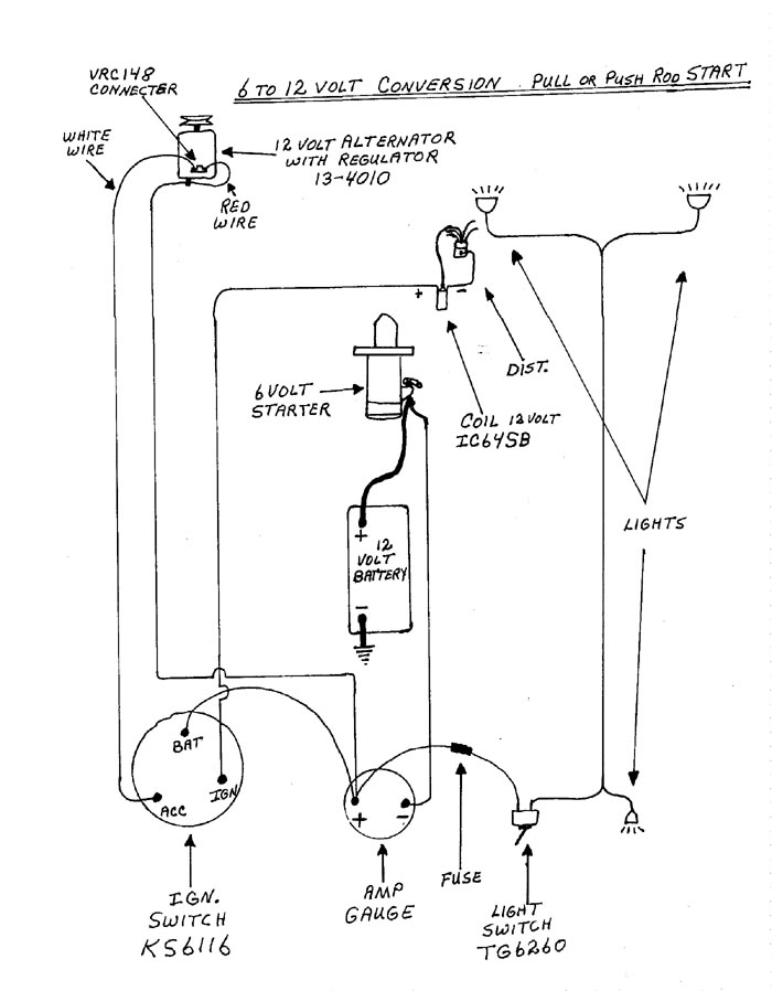
|
|
Bob, North Carolina
1949 B
|
|
CTuckerNWIL
Orange Level

Joined: 11 Sep 2009
Location: NW Illinois
Points: 22810
|
Post Options
Thanks(0)
Quote Reply
Posted: 23 Jul 2010 at 3:03pm |
|
The diode is in backwards.
|
|
|
|
dadsdozerhd5b
Orange Level
Joined: 27 Sep 2009
Location: lansdale pa.
Points: 527
|
Post Options
Thanks(0)
Quote Reply
Posted: 23 Jul 2010 at 8:46pm |
still does not settle the issue. does the wire #1 or white wire on bee's diagram need to be hooked up to anything? reliable alternator rebuilder that gave me my diagram said it was optional as in remember but my memory is getting foggy. does an ign. switch give voltage to the acc terminal when key is on? i never checked.
|
|
HD5B, HD5G, (2) FARMALL A's, CUB. DO IT RIGHT THE FIRST TIME, IGNORE THE LAUGHTER. FLANNEL IS ALWAYS IN STYLE.
|
|
Pippin5267
Bronze Level
Joined: 16 Jul 2010
Location: Bristol, TN
Points: 15
|
Post Options
Thanks(0)
Quote Reply
Posted: 23 Jul 2010 at 8:54pm |
|
Sorry for all the replys everyone. Apparently the diagram was right and I just had the diode backwards. I thought I tried it both ways last night but I must have had it the same way both times. I turned it around this morning and now the ingition switch works exactly as it should. The alternator is charging 13.8 at idle and 14.4 at wide open throttle. Thanks for the help everyone.
|
|
steve(ill)
Orange Level Access
Joined: 11 Sep 2009
Location: illinois
Points: 77708
|
Post Options
Thanks(0)
Quote Reply
Posted: 23 Jul 2010 at 9:15pm |
|
yes dad, you need both wires. the #1 wire is 12 volt excitation to make the alternator kick in and charge... the #2 wire should be always hot and jumpered to the lug on the back of the alternator that is connected to the ampmeter- then battery.
|
|
Like them all, but love the "B"s.
|
|
Gerald J.
Orange Level
Joined: 12 Sep 2009
Location: Hamilton Co, IA
Points: 5636
|
Post Options
Thanks(0)
Quote Reply
Posted: 28 Jul 2010 at 5:42pm |
|
The ammeter tells you what the battery is takeing and supplying. The voltmeter tells you that if the battery was connected it might charge unless sulfated. The voltmeter does not tell the battery is truly taking a charge.
The ammeter is no more fire hazard than all the rest of the wiring that remains energized with the switch off.
Its more convenient to install a voltmeter, but much less instructive.
Gerald J.
|
|
firebrick43
Orange Level
Joined: 10 Dec 2009
Location: Warren County
Points: 592
|
Post Options
Thanks(0)
Quote Reply
Posted: 29 Jul 2010 at 12:29pm |
|
Gerald, I respectfully disagree.
But don't believe me, listen to a gauge expert.
http://www.autometer.com/tech_faq_answer.aspx?sid=1&qid=5
The amp capacity of an 8 gauge wire is much higher than an 18 or 20 gauge wire. This is what has the propensity of causing a fire. An voltmeter keeps the amperage away from the confines of the dash. And as such its very simple to fuse the low current going into the dash, not so with 60+ amps to an ammeter, that is live all the time.
I have seen a fire do just to corroded/bad connections at the ammeter gauge itself, never seen one do to an voltmeter.
A charging system due to a bad regulator, can charge below normal voltage, say at 12 volts, and then you are sulfating the plates, but you would never know with an ammeter. You know if the battery is sulfated with a voltmeter, especially if its badly sulfated, it would indicate high voltage, ie 15.5~. Also you can do a quick charge test with a voltmeter that is impossible with an ammeter. If the vehicle has been run recently(or battery charged) in the past 12 hours but not within say 3 or 4 hours. Without starting the vehicle, turn the headlights on for a minute or two to remove any surface charge. Then turn them off and read the voltmeter. If at 12.7 your battery is good, if below 12.4 it not fully charged, and has issues somewhere. If your alternator is not keeping up or is bad you voltage is going to drop off, below 13.6 after a few minutes.
Warning the voltmeter applies to three wire alternators which is the bases of this thread. One wire alternator(piss poor choice) and generators, can benefit from an ammeter as they can discharge at lower rpms and you won't know it. Really both would be more helpful in these systems. A 3 wire alternator compensates for rpm in it regulator circuit.
|
|
Brian Jasper co. Ia
Orange Level
Joined: 11 Sep 2009
Location: Prairie City Ia
Points: 10508
|
Post Options
Thanks(0)
Quote Reply
Posted: 29 Jul 2010 at 12:43pm |
|
I'm going to agree with Firebrick on there being more chance of fire from an electrical problem with an ammeter over a volt meter. I agree with Gerald that the ammeter gives a better indication of what's going on. I had an added on ammeter in an old Maverick back in high school. One day driving everything went dead and smoke from under the hood. Turns out the ammeter wires rubbed through and started a small fire. Nothing a Big Gulp couldn't put out. As long as wires are safely routed and overload protected, I'm all for an ammeter.
|
|
"Any man who thinks he can be happy and prosperous by letting the government take care of him better take a closer look at the American Indian." Henry Ford
|
|
firebrick43
Orange Level
Joined: 10 Dec 2009
Location: Warren County
Points: 592
|
Post Options
Thanks(0)
Quote Reply
Posted: 29 Jul 2010 at 12:56pm |
|
It also appalls me that neither of the circuit diagrams have fusible links or main charging system fuses! The fuse in the second diagram while not a bad idea is really not protecting the main part of the system. And the second diagram doesn't have a diode or idiot light to prevent possible back feeding, and thus battery discharge when the tractor is shut off
|
|
jaybmiller
Orange Level Access
Joined: 12 Sep 2009
Location: Greensville,Ont
Points: 21462
|
Post Options
Thanks(0)
Quote Reply
Posted: 29 Jul 2010 at 12:58pm |
Sorry guys but my vote is for the ammeter. A properly working Ammeter will NEVER cause a fire.Mind you , I only have 50 years of working with them, NEVER had a fire. However just like ANY other piece of equipment, it 'might' fail.We just had a small plane return to the airport with a 'smoke under the dashboard' report, so even NEW equipment can fail.
An ammeter will tell you the rate of charge or discharge in a circuit, a voltmeter only the voltage where it is attached.Each tells a different story as to the conditions that exist in the tractor, car,plane or train....
Maintenance is the critical issue. Wires are NOT supposed to rub,connections should NOT be corroded, and terminals should be tight and clean.We all get lulled into, 'it's working ok...carry on' syndrome. Heck, do you check the engine oil level EVERYTIME before you startup ??? See... I caught you !!!LOL
Jay
|
|
3 D-14s,A-C forklift, B-112
Kubota BX23S lil' TOOT( The Other Orange Tractor)
Never burn your bridges, unless you can walk on water
|
|