This site is not affiliated with AGCO Inc., Duluth GA., Allis-Chalmers Co., Milwaukee, WI., or any surviving or related corporate entity. All trademarks remain the property of their respective owners. All information presented herein should be considered the result of an un-moderated public forum with no responsibility for its accuracy or usability assumed by the users and sponsors of this site or any corporate entity.
The Forum Parts and Services Unofficial Allis Store Tractor Shows Serial Numbers History
Forum Home Forum Home > Allis Chalmers > Farm Equipment
  New Posts New Posts
  FAQ FAQ  Forum Search   Events   Register Register  Login Login


CA Project Pics

 Post Reply Post Reply Page  <123
Author
Message
dfwallis View Drop Down
Silver Level
Silver Level


Joined: 09 Mar 2023
Location: DFW
Points: 375
Post Options Post Options   Thanks (0) Thanks(0)   Quote dfwallis Quote  Post ReplyReply Direct Link To This Post Posted: 16 Oct 2023 at 6:45pm
Originally posted by JK in Pa JK in Pa wrote:

I believe I see valve rotators on the exhaust valves. I always thought valve rotators required offset rockers.

Offsetting was sometimes used in small engines when no valve rotation device was present to achieve rotation.  Offsetting is not supposed to be needed with a valve rotation device.  It certainly should not be so far off that it's barely contacting the valve stem and leaving giant divots because of force being limited to a tiny contact area.
Back to Top
Sponsored Links


Back to Top
1955CA View Drop Down
Orange Level
Orange Level
Avatar

Joined: 10 Sep 2018
Location: Ontario, Canada
Points: 514
Post Options Post Options   Thanks (0) Thanks(0)   Quote 1955CA Quote  Post ReplyReply Direct Link To This Post Posted: 18 Oct 2023 at 10:45am
Any update pics DFWallis? That looks wicked with the big tires. I just went stock size on my rear replacements. Can't wait to see it all put back together after you had the body parts painted.

I just came in from my morning fall ride on mine. Took the dog for a walk, so figured I'd give Allis a run too.
Back to Top
dfwallis View Drop Down
Silver Level
Silver Level


Joined: 09 Mar 2023
Location: DFW
Points: 375
Post Options Post Options   Thanks (0) Thanks(0)   Quote dfwallis Quote  Post ReplyReply Direct Link To This Post Posted: 18 Oct 2023 at 5:56pm
Originally posted by 1955CA 1955CA wrote:

Any update pics DFWallis? That looks wicked with the big tires. I just went stock size on my rear replacements. Can't wait to see it all put back together after you had the body parts painted.

I just came in from my morning fall ride on mine. Took the dog for a walk, so figured I'd give Allis a run too.

I just posted updates a few days ago.  It's not back together yet but mostly finished the engine rebuild internals.  I'm working on some hydraulic system mods at the moment.  I'm creating a pedestal out of a trailer pintle hitch and a hitch extension to get me the required height above the tires.  I've got the base complete except for painting.  I'll start on the platform for mounting the spools tomorrow when a connector arrives and i can determine the width of the side by side spool sets/valves.  I don't expect any significant progress before the spring.  I hate working in the cold :(
Back to Top
1955CA View Drop Down
Orange Level
Orange Level
Avatar

Joined: 10 Sep 2018
Location: Ontario, Canada
Points: 514
Post Options Post Options   Thanks (0) Thanks(0)   Quote 1955CA Quote  Post ReplyReply Direct Link To This Post Posted: 18 Oct 2023 at 7:48pm
Originally posted by dfwallis dfwallis wrote:

Originally posted by 1955CA 1955CA wrote:

Any update pics DFWallis? That looks wicked with the big tires. I just went stock size on my rear replacements. Can't wait to see it all put back together after you had the body parts painted.

I just came in from my morning fall ride on mine. Took the dog for a walk, so figured I'd give Allis a run too.

I just posted updates a few days ago.  It's not back together yet but mostly finished the engine rebuild internals.  I'm working on some hydraulic system mods at the moment.  I'm creating a pedestal out of a trailer pintle hitch and a hitch extension to get me the required height above the tires.  I've got the base complete except for painting.  I'll start on the platform for mounting the spools tomorrow when a connector arrives and i can determine the width of the side by side spool sets/valves.  I don't expect any significant progress before the spring.  I hate working in the cold :(

Awesome! I'll be watching for your future updates. You might teach me a few tricks to do to my CA.
Back to Top
dfwallis View Drop Down
Silver Level
Silver Level


Joined: 09 Mar 2023
Location: DFW
Points: 375
Post Options Post Options   Thanks (0) Thanks(0)   Quote dfwallis Quote  Post ReplyReply Direct Link To This Post Posted: 30 Oct 2023 at 9:25pm
Progress 10/30/2023:  Designing a removable hydraulic console intended to bolt to the left side fender.  The console consists of a pintle hitch, and a hitch extender mounted vertically with a custom tray resting on top of the extension which is removable.  Two single acting valves mount to the side, a 4 spool valve set on the top.  It sticks out over the tractor tire for space reasons.  It may or may not fit exactly where I designed it to sit (may be too close to the seat), but I can move it forward or backward if needed.  The tray itself is designed to slide left or right.  I still have some plumbing work to go for the return.  Perhaps a little goofy, but fun anyway (I'm retired, I got time) :)  It weighs a ton...

The back view showing the mechanism for sliding the tray left or right.


It includes optional hose supports that can be added or removed when the dual acting spool valves on top are used.  


Closeup of a hose support.  Since the dual acting valve hoses will come off straight up, this supports them at about 16 inches (can be lowered) to prevent sharp bends.


Back to Top
steve(ill) View Drop Down
Orange Level Access
Orange Level Access
Avatar

Joined: 11 Sep 2009
Location: illinois
Points: 78367
Post Options Post Options   Thanks (0) Thanks(0)   Quote steve(ill) Quote  Post ReplyReply Direct Link To This Post Posted: 31 Oct 2023 at 8:15am
so the vertical hitch is just a way to mount it to the tractor , so you can easily remove it when not needed ? .... Instead of bolts ? .... I see the threaded rod which allows you to adjust it in that direction.
Like them all, but love the "B"s.
Back to Top
dfwallis View Drop Down
Silver Level
Silver Level


Joined: 09 Mar 2023
Location: DFW
Points: 375
Post Options Post Options   Thanks (0) Thanks(0)   Quote dfwallis Quote  Post ReplyReply Direct Link To This Post Posted: 31 Oct 2023 at 11:31am
Originally posted by steve(ill) steve(ill) wrote:

so the vertical hitch is just a way to mount it to the tractor , so you can easily remove it when not needed ? .... Instead of bolts ? .... I see the threaded rod which allows you to adjust it in that direction.

The bottom (pintle mount) section will be bolted to the fender wall.  I haven't drilled those holes (in the pintle bracket) yet so I can determine the best position.  I measured it and know very close where the holes will go but I made the bracket a little longer in case I need to adjust it right or left.  The top section is the removable part via the hitch pin.  I'm trying not to physically modify the tractor, just using existing bolt patterns as much as possible.  The threaded rod is designed to allow the tray to slide left or right (it is then tightened in that left or right position).  I was thinking ahead to deconflict it with my idea for a roll bar/canopy mount that mounts to the axle but will rise just outside the fender wall (so the wheels will have to be slightly spun out).  When that roll bar/canopy is installed, the tray will have to be slid right/forward to deconflict (since it sticks out over the tire).  The pintle hitch is mounted to a piece of 4 inch x 4 inch angle iron that I cut out the left and right floor sections.  The right section had to be cut to deconflict with the brake lever.  The left side was only cut for symmetry.  The forward fender bolt is around 4 inches from hole to back of brake lever.  The other fender bolt is 11 inches behind the forward fender bolt.  I have about an inch of play to adjust the position to deconflict with the brake lever and the seat.  

The console is fairly well balanced.  There is little stress on the mount when you operate the spool levers which have quite strong springs.  That was one worry with only having two mounting bolts.  I can add a horizontal support later if needed.


Back to Top
1955CA View Drop Down
Orange Level
Orange Level
Avatar

Joined: 10 Sep 2018
Location: Ontario, Canada
Points: 514
Post Options Post Options   Thanks (1) Thanks(1)   Quote 1955CA Quote  Post ReplyReply Direct Link To This Post Posted: 01 Nov 2023 at 5:35am
Wow! Nice!
Back to Top
dfwallis View Drop Down
Silver Level
Silver Level


Joined: 09 Mar 2023
Location: DFW
Points: 375
Post Options Post Options   Thanks (0) Thanks(0)   Quote dfwallis Quote  Post ReplyReply Direct Link To This Post Posted: 25 Jan 2024 at 3:14pm
My first draft of the hydraulic return for a CA.  I will first attempt return via filler cap as in below.  If that doesn't work well, I have a better idea, but I think this will be ok if the flow is sufficient.  Since the pump will be pulling out as fast as it's going back in, I don't anticipate problems, but I'll find out I guess.  It's likely I'll have to reduce the size of the brass nut a little, but that's pretty easy.  I may also need an o-ring.  I had to bore the hole in the stainless fitting out to 3/8 inch (my poor drill bits).  It was a 3/8 inch fitting with a 1/4" hole :(  Was designed for super high pressure but not needed on the return line.


Edited by dfwallis - 25 Jan 2024 at 3:15pm
CA13092
Back to Top
dfwallis View Drop Down
Silver Level
Silver Level


Joined: 09 Mar 2023
Location: DFW
Points: 375
Post Options Post Options   Thanks (0) Thanks(0)   Quote dfwallis Quote  Post ReplyReply Direct Link To This Post Posted: 03 May 2024 at 12:12pm
Traveling this weekend to resume work.  I probably won't post real time due to lack of cell service, but expect a few progress pics late May or early June :)  In order, finish engine work (rebuilt last fall), front tin work (partly complete, blast and paint, hopefully the de-dented gas tank is ready from the body work guy, you'd think 8 months would be enough time), rewire (partly complete), first start, then move on to the rear half (shifter back), finish steering wheel resurface (mostly complete), hand clutch rebuild, weld up and seal final drive oil pans, sand blast and paint rear half, complete custom 3pt mods and custom hydraulic mods last (well some will have to be done before I reinstall the platform).  At some point I need to rework the front wheel bearings, but that can wait. 
CA13092
Back to Top
dfwallis View Drop Down
Silver Level
Silver Level


Joined: 09 Mar 2023
Location: DFW
Points: 375
Post Options Post Options   Thanks (0) Thanks(0)   Quote dfwallis Quote  Post ReplyReply Direct Link To This Post Posted: 26 May 2024 at 11:05am
Update 05/26/2024:  

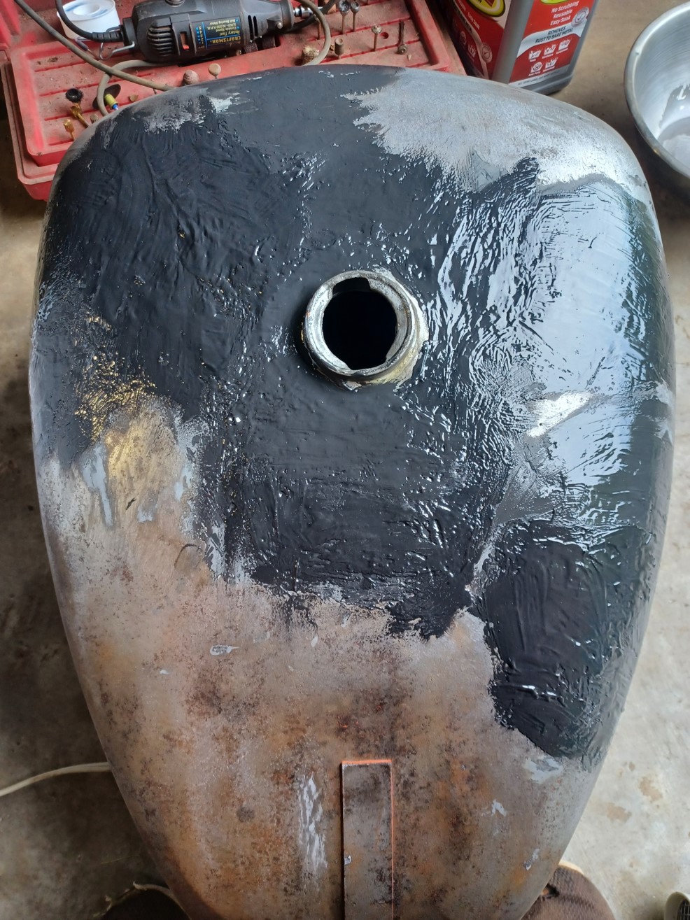
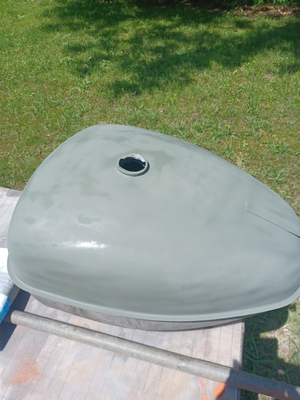
Quite a bit of trouble getting the severely dented gas tank fixed (someone felled a tree on it).  First took it to a large body shop.  They had it for a few weeks and decided they couldn't fix it (welded pins method).  The metal was too thick and the pins detached.  Then took it to a tractor renovation place and left it for 8 months (apparently out in the weather, I had to repeat the derust process).  They assured me repeatedly they'd have it ready but when I finally arrived they had not been able to find anyone to work it.  So I started driving from shop to shop and finally found a semi-retired guy to fix it (for a very reasonable price).  He did a pretty good job given the condition (yes I could have replaced it).  Needless to say, this caused quite a bit of delay/progress hindrance.  It came out looking pretty good.  The paint doesn't look quite as good as I'd like.  Really bad conditions:  1) Indiana is pretty darn wet and humid in May and I just could not get the water down in the line.  2) Bugs galore.  Wet paint seems like a bug magnet.  3) Sandable primer (600 grit) just never got smooth enough.  4) Oil based enamel paint takes weeks to dry and gets lots of dings if you're in a hurry.  Doing it over I'd use a faster drying paint.  The primer I used dries in minutes and is hard as a rock.


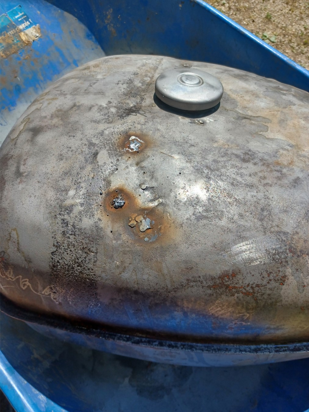
There were a few leaks in the top left over from the welded pins which I had to weld up.  Then I used epoxy as the major filler and finished with a skim coat of bondo (no picture, I kept forgetting to take pictures).


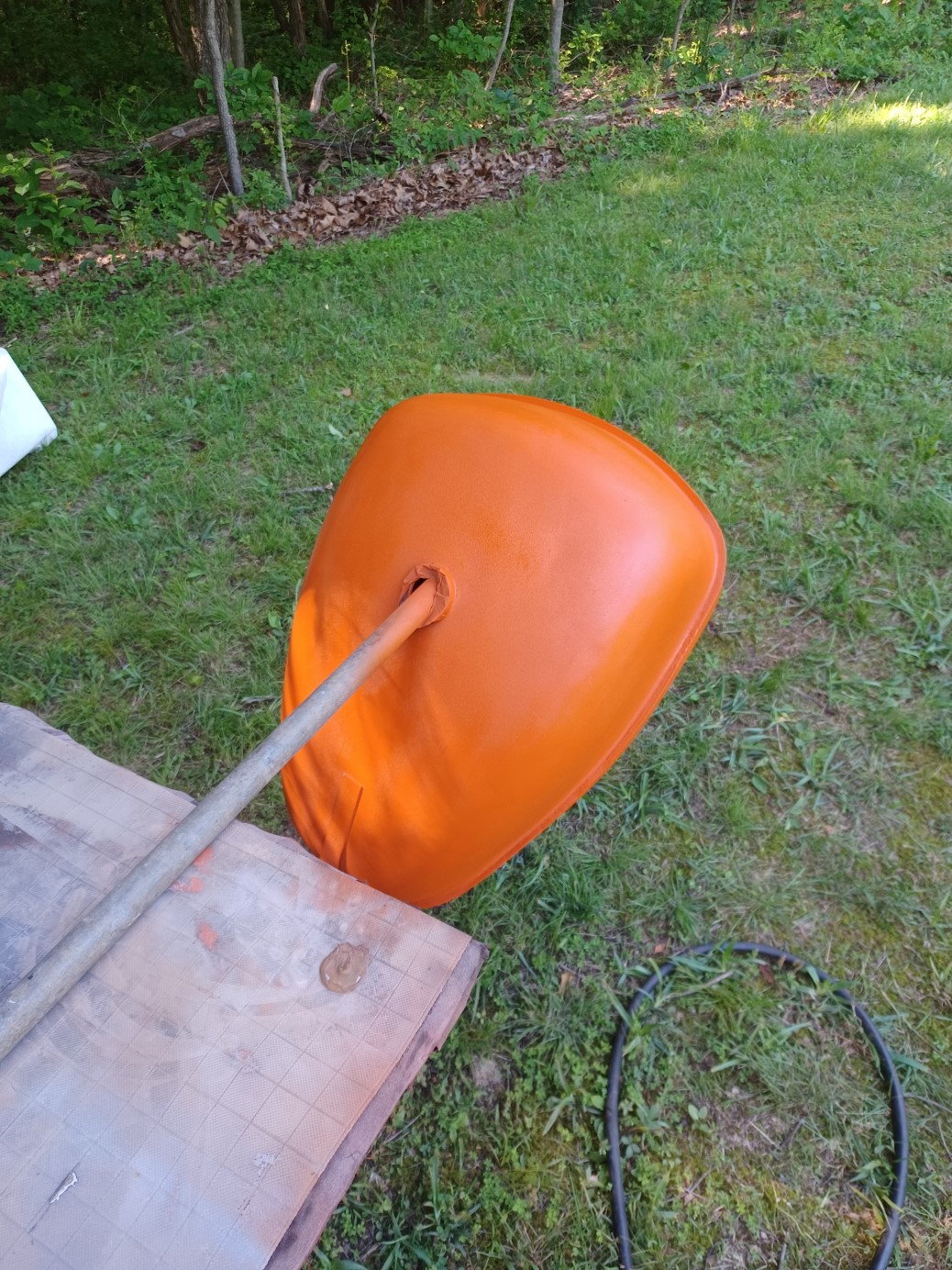
Fit check.  I should not have put the strap on yet.  The paint was still too wet although dry to the touch.  The strap goes on over the tin not the tank.  Had to make a small paint repair to the tank but it will be hidden under the tin.  I had used a rubber strip on the strap rather than a nylon strap material (fixed later).  The rubber was really sticky and welded itself to the paint :(  The tank was also internally derusted (6 or 7 times) and POR 15 gas tank sealer applied.  That stuff seems pretty good.  Hard as a rock, coated very well.


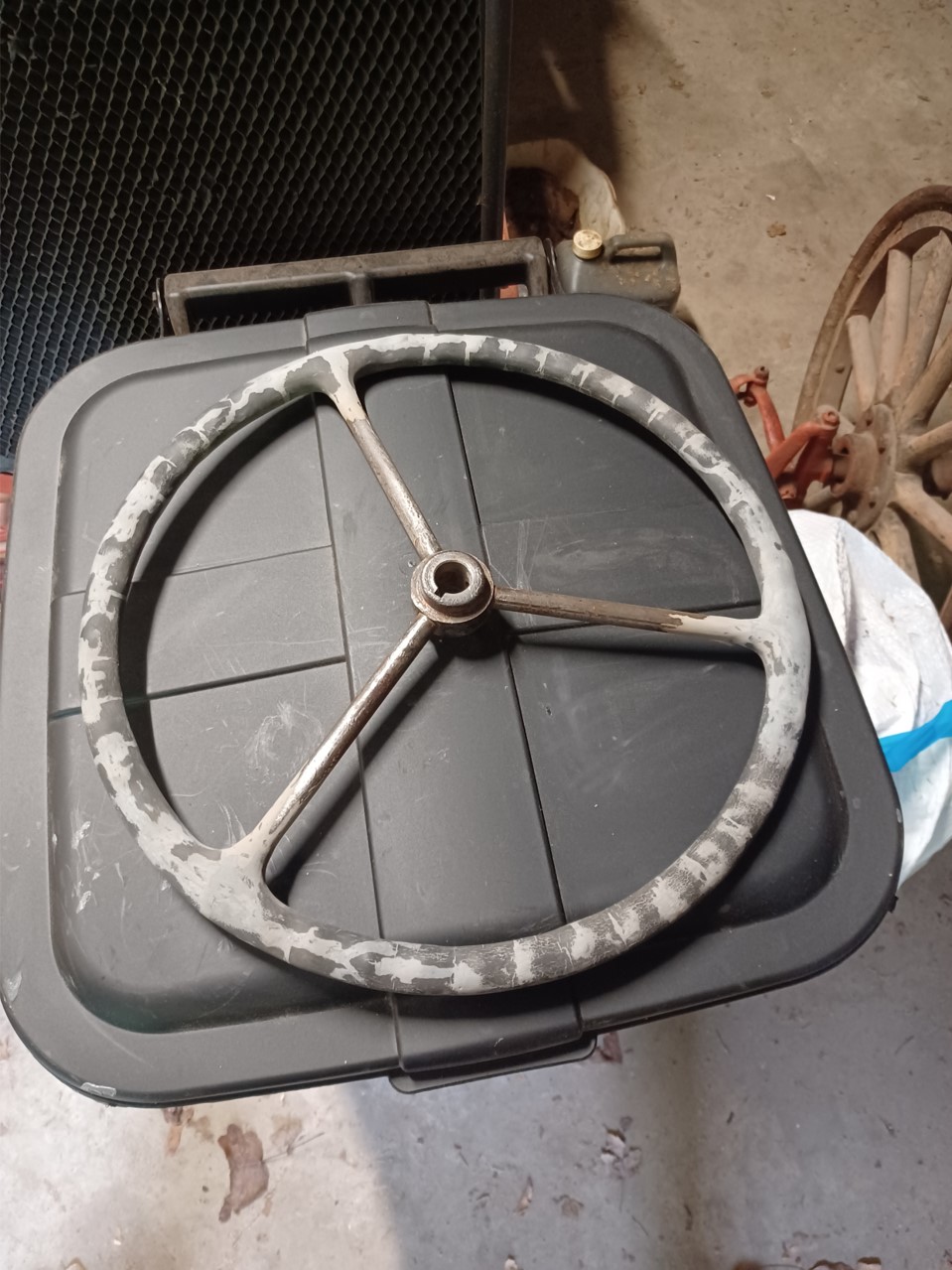
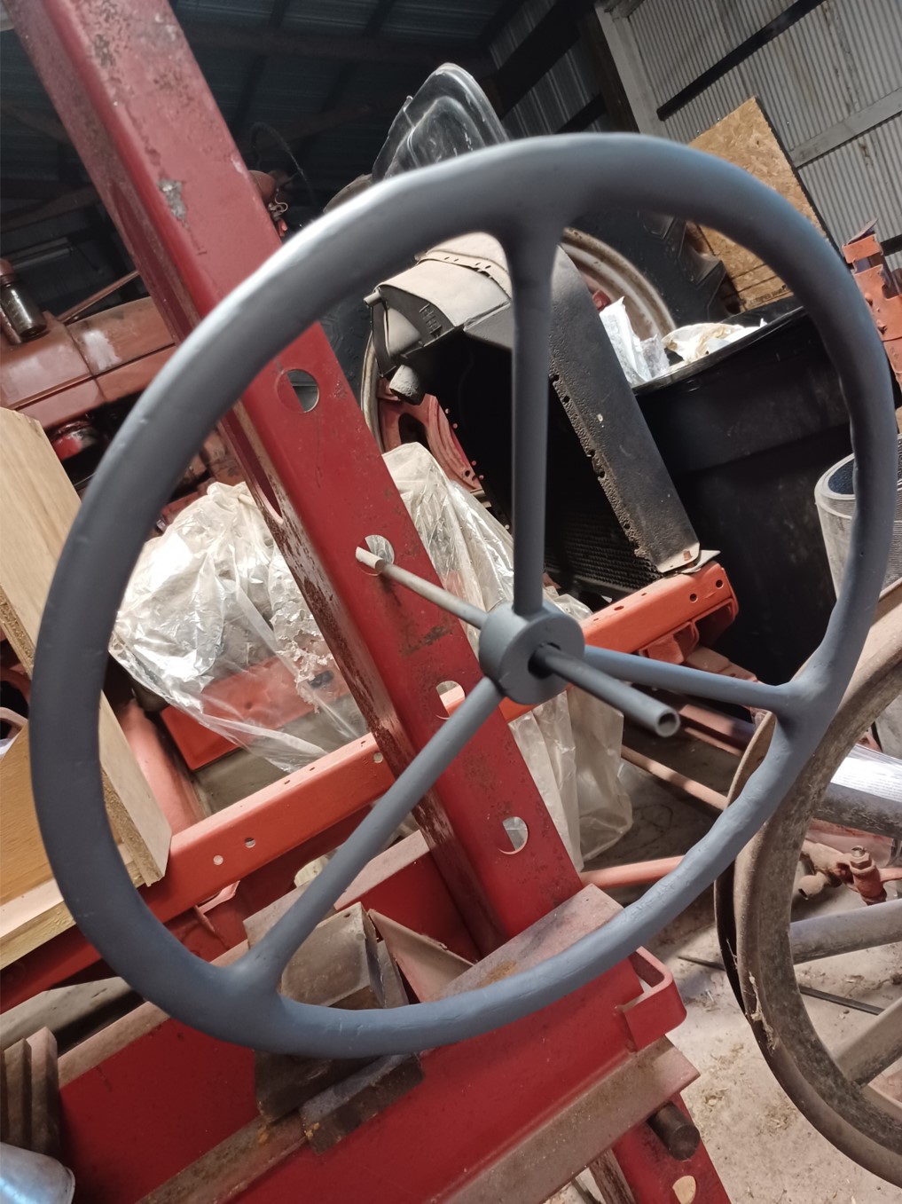
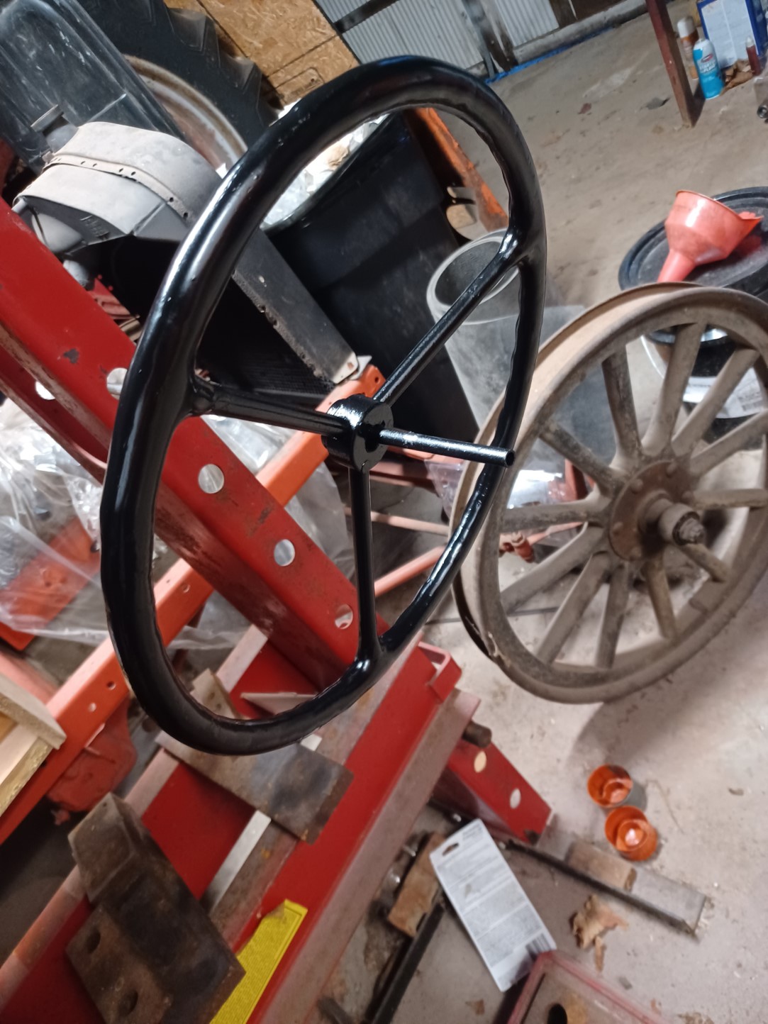
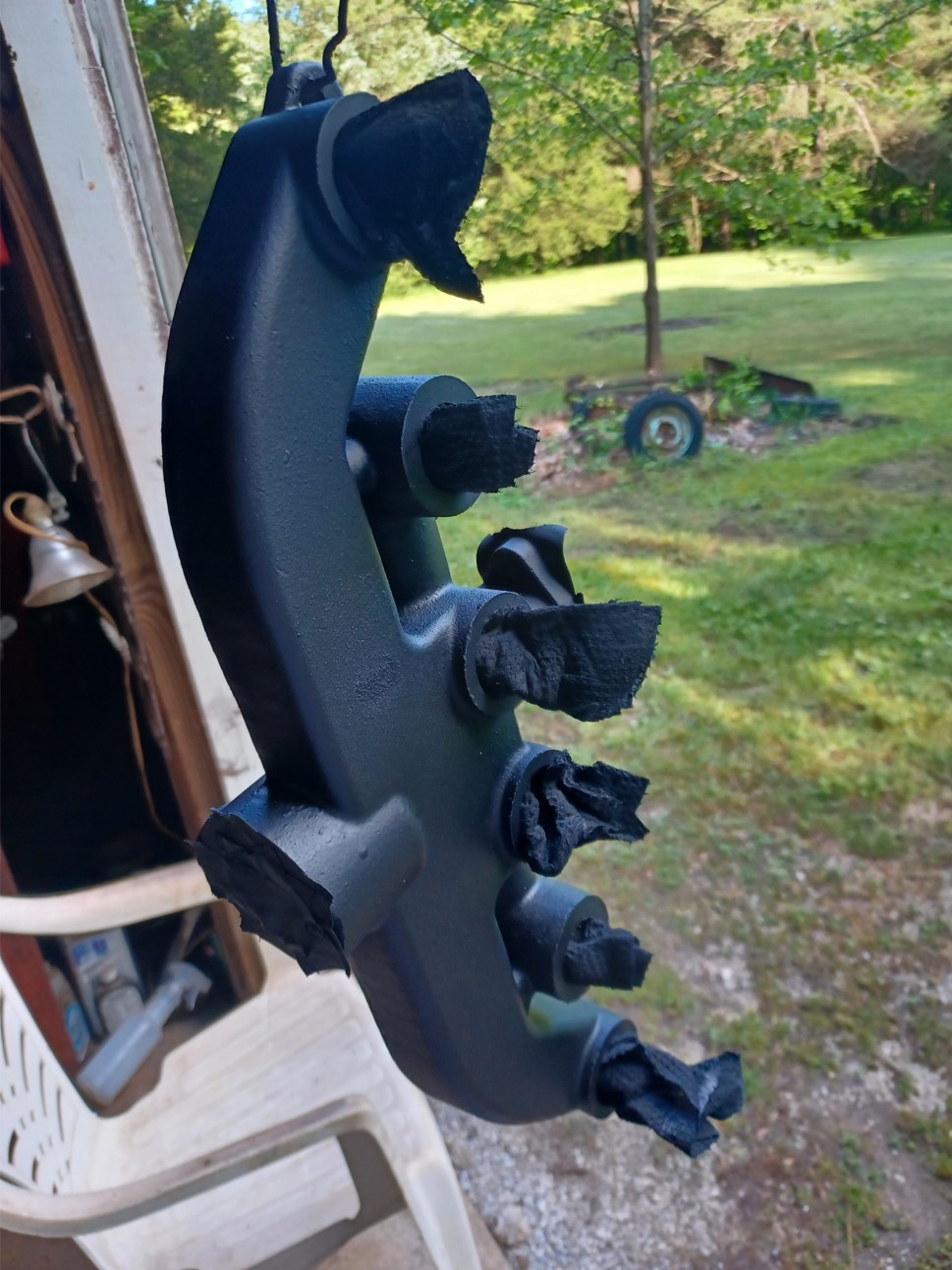
I worked on the steering wheel off and on between paint coats and maximized multitasking as much as possible.  The original was in really bad shape with most of the bakelight near each spoke all or nearly all missing.  That was a lot of small batch mixing.  Yes I could have bought 2 of them for the price of the epoxy (not to mention my time).  I could have spent a bit more time glazing.  Epoxy isn't very well suited to that.


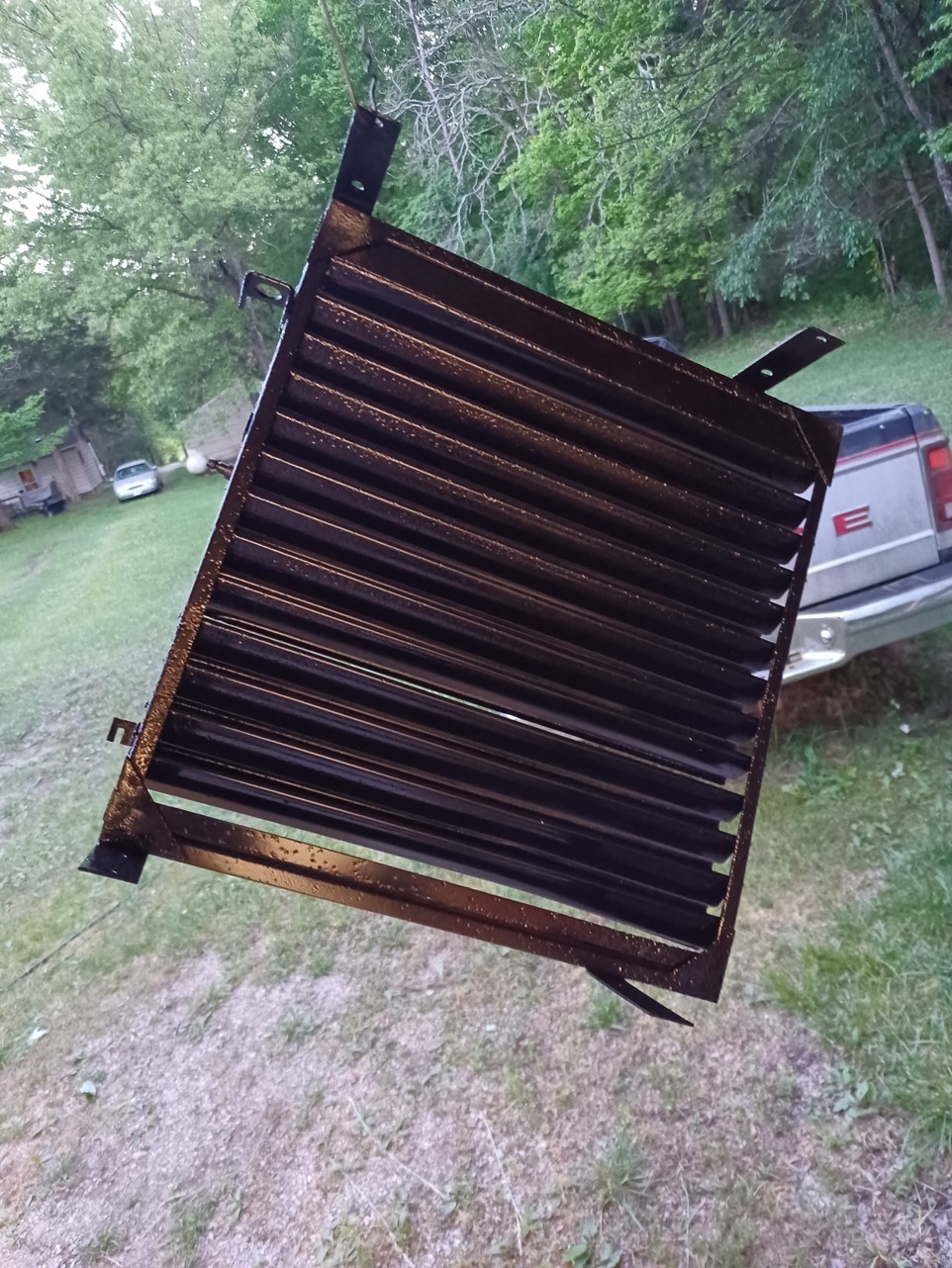
Sand blasted and made some minor repairs to the original shutters.  They were in really good shape except for one torn hinge.


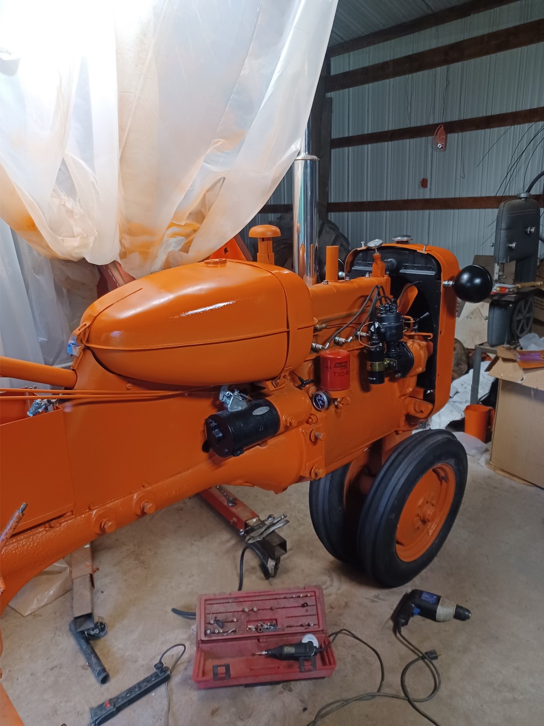
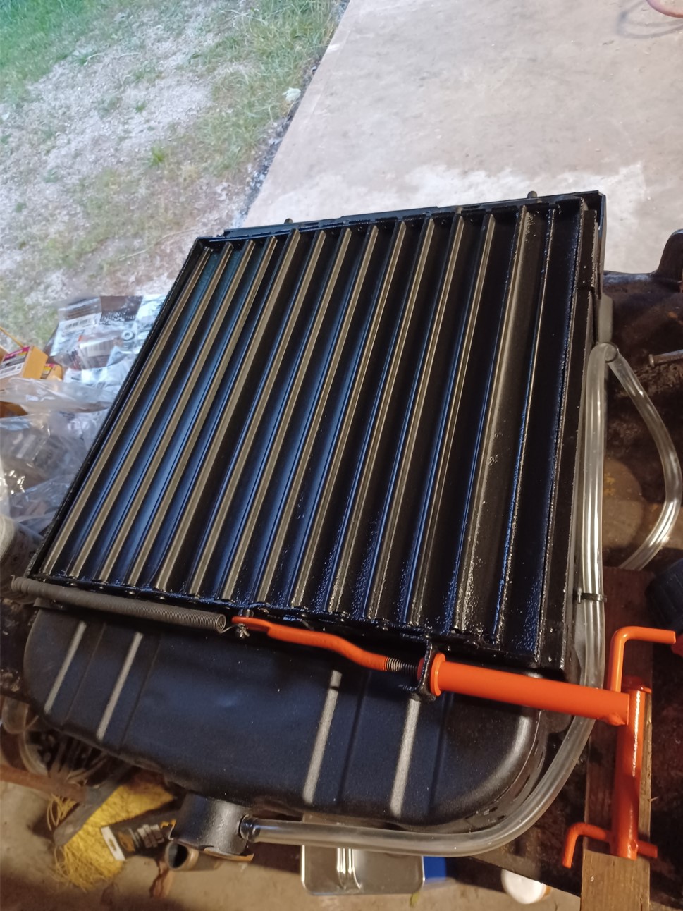
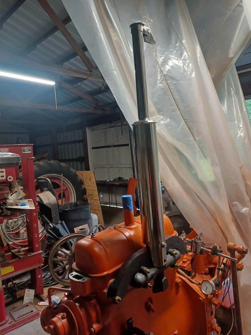
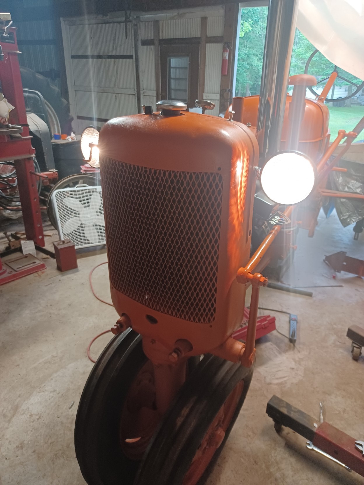
Installed.  This pic also shows the aftermarket radiator overflow tube.  The nipple sticks out way too far and the hose gets crushed by the cowling.  I shortened it and routed a smaller diameter tube differently.  I'm not quite happy with it and will probably improve it later.  The original radiator has a deep recess in the top for the tubing.  Again the aftermarket radiator shutter mounting holes didn't line up but was a simple hole size increase to fix adequately.


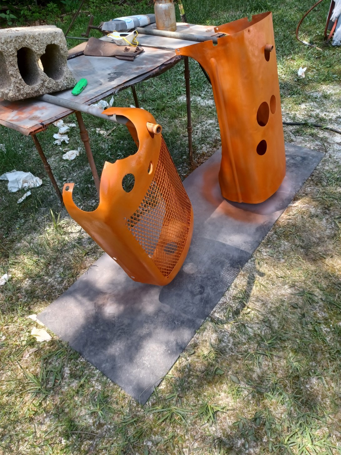
2000f paint on the new manifold.


Manifold and muffler installed:


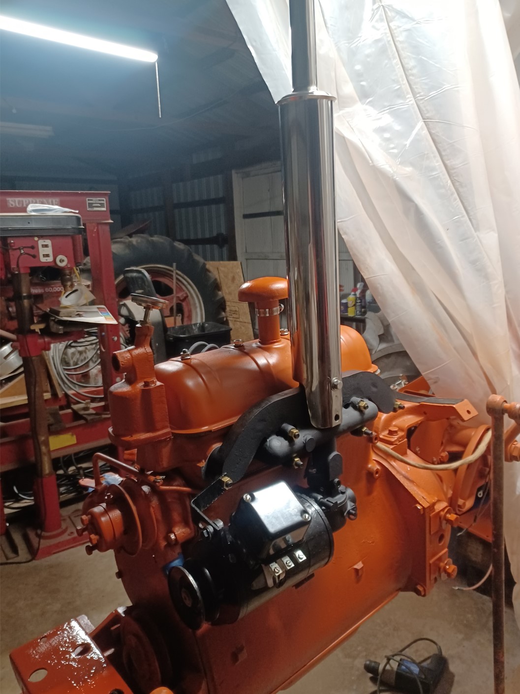
Rebuilt original generator with regulator and rebuilt carb installed:


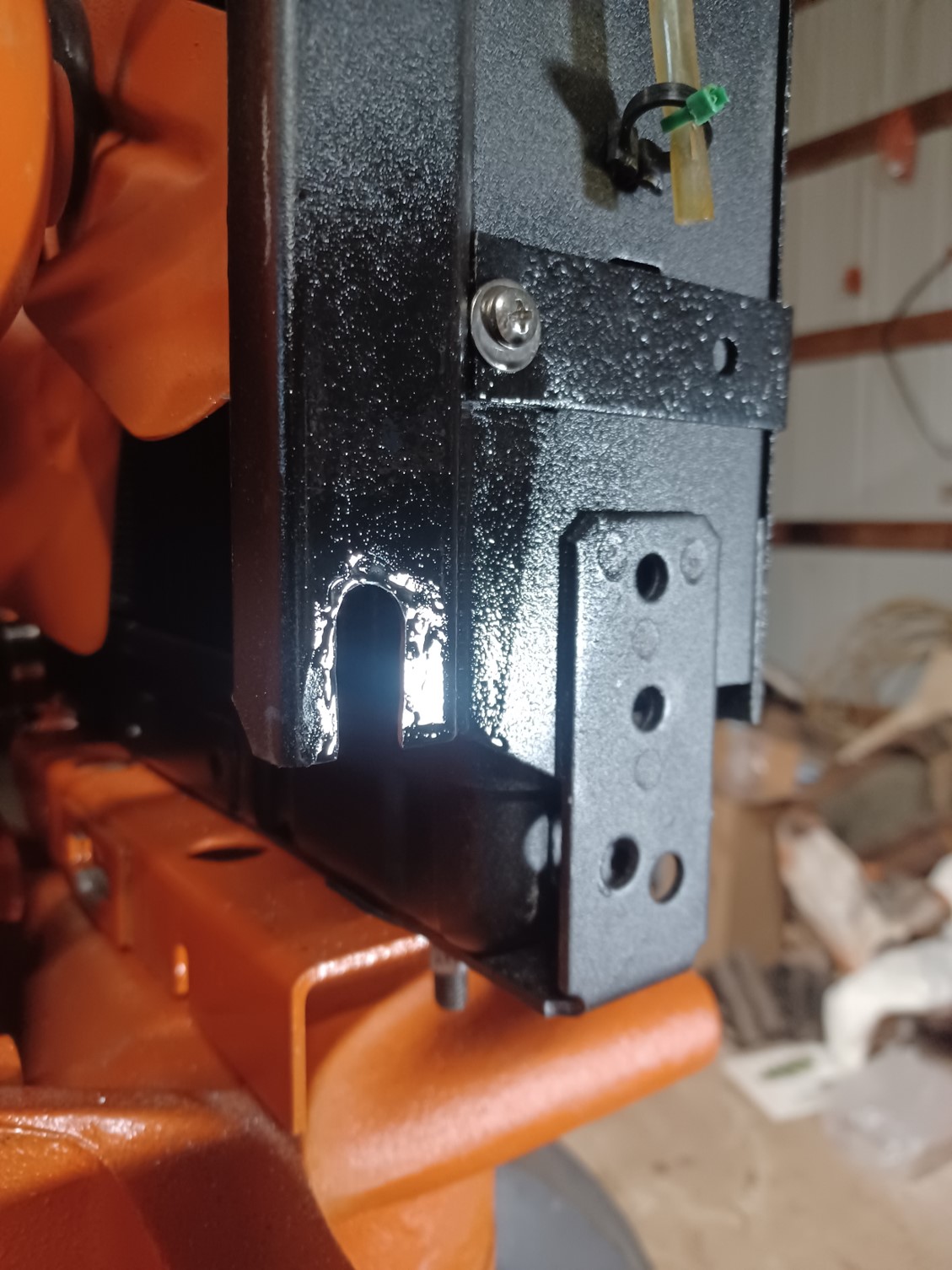
The mounting holes in the aftermarket radiator (made in Turkey) for the cowling didn't match up.  I had to increase the hole sizes for the bottom 2 holes (were 1/4 inch holes) to 3/8 inches and then had to slot the bottom holes because they still would not line up by 3/8 or so.


After reversing the radiator mounting plate to position the "hole reinforcement" towards the engine, the radiator fit properly.  This is after I rewired and installed the lights and battery.  I also had to clean up the threads on the large steering linkage on the lefthand side of the tractor.  I then installed two new castle nuts.


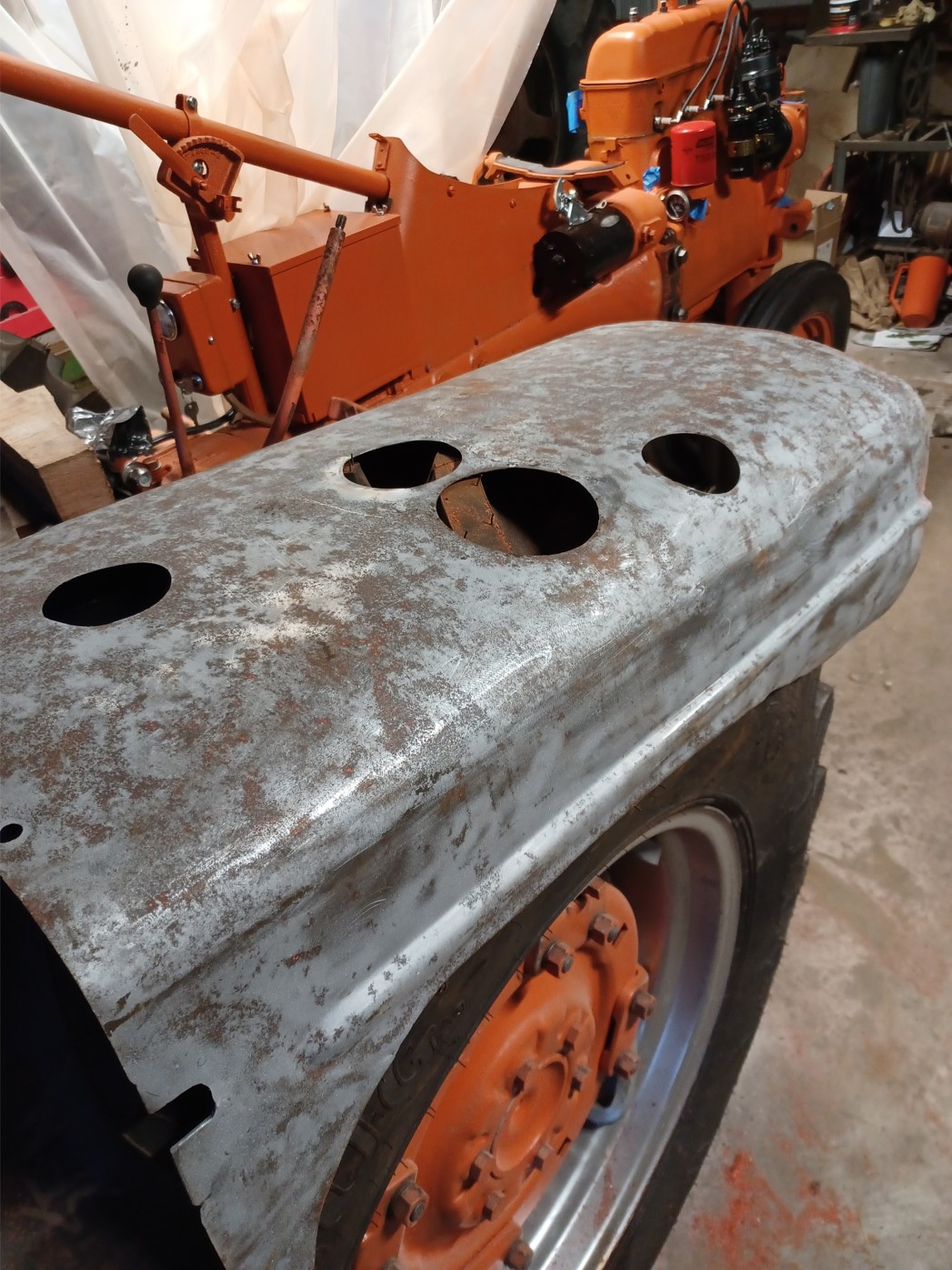
Likewise, the hood was pretty beat up.  I worked for hours trying to get it straight enough to avoid bondo, but failed.  I don't have the nice body metal working tools there that I have at home.  But I was running out of time so I'll consider further improvements in the future.  The hood and radiator cowling were also welded up by a body shop due to various rips and tears around the mounting holes and the oil filler hole.  The headlights were basically decapitated at some point.  One could have been easily renovated but the second one would have taken quite a bit of effort (still doable), but I elected to get new ones.


I was running out of time so I elected to do a good enough for now effort on the tin.  I can easily address that later.  There is more functional work to be done first.


We were able to get the engine to fire and briefly run.  It sounded really good, all 4 cylinders fired.  However, there seems to be a fuel problem.  I suspect my carb rebuild went astray somewhere.  There was one jet I was unable to remove and replace, but it was nice and clean.  Also, the new battery I installed was discharged when I bought it and self discharged overnight (I checked for leakage and didn't measure any).  The behavior is kind of strange with the charger, but it is one of those "automatic" chargers.  I just want a switch to select 6V and an ammeter to tell whether it's sending current in.  Basically, at 100% charge it turns the engine over really well...for 2 revolutions then it can barely turn it to the next compression stroke.  Charge it back up, you get 2 good revolutions then the same behavior.  Put it on a load tester, shows good though.  I don't trust the load tester.  The guy at OReilly told me he's never sold a 6V battery before.  I suspect it was in the back uncharged for years.  After a full charge (100%), if I disconnect the charger, wait 30 seconds and restart the charging, it behaves as if self discharged.  One time the charge indicated it started over at 13%, the next time at 70%.  I don't trust the battery or the charger :(  

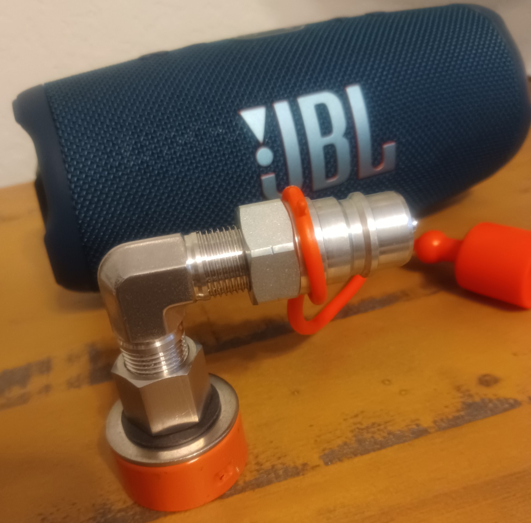
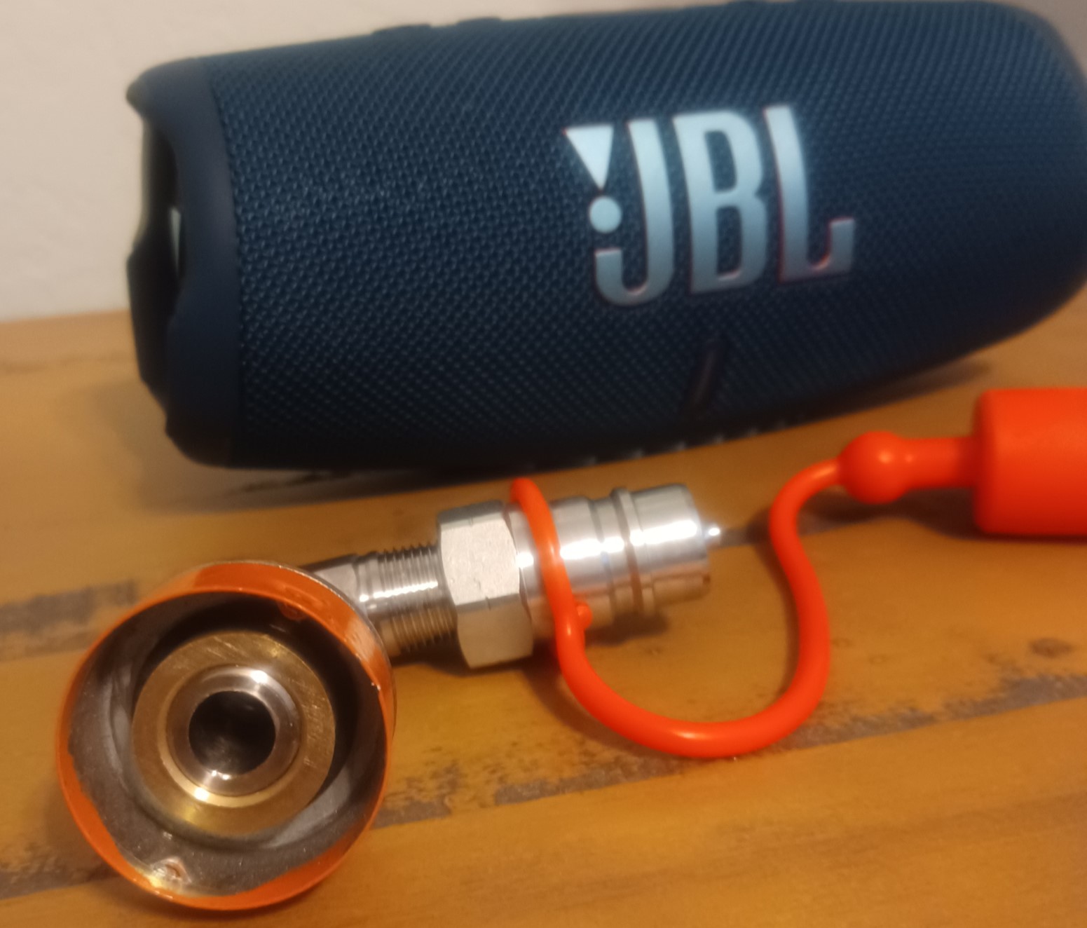
I also had an issue with an aftermarket fuel bowl.  It absolutely would not screw into the gas tank.  Any of several 3/8 pipe fittings I had laying around worked fine and easily screwed in.  I ended up having to buy a die and "fix" the threads.  Even then, it wasn't really happy screwing in straight.  But I finally got it to go in properly.  I fear though next time I remove it to clean/replace the screen, I may not be able to get it back in straight.

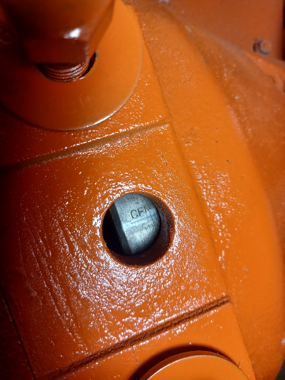
So, in working on the timing, we found the FIRE mark on the flywheel.  Then we found a CENter mark just after the fire mark...then we found a second CENter mark.  Are there two center marks??


Edited by dfwallis - 27 May 2024 at 10:42am
CA13092
Back to Top
dfwallis View Drop Down
Silver Level
Silver Level


Joined: 09 Mar 2023
Location: DFW
Points: 375
Post Options Post Options   Thanks (0) Thanks(0)   Quote dfwallis Quote  Post ReplyReply Direct Link To This Post Posted: 01 Jun 2024 at 11:19am
I discovered that the paint I've been using (Tallman's) is actually made by Van Sickle.  My substandard results are mostly my deficient painting environment and failure to add the hardener recommended.  They also have a hard clear coat to add some more gloss.  The paint itself isn't extremely glossy.  The spray can version also refers to "flat" paint, but it clearly isn't flat.  I've also been rushing it a bit to try to squeeze a huge amount of work in my short trips.  I'm clearly not a painting expert, sadly.
CA13092
Back to Top
 Post Reply Post Reply Page  <123
  Share Topic   

Forum Jump Forum Permissions View Drop Down

Forum Software by Web Wiz Forums® version 11.10
Copyright ©2001-2017 Web Wiz Ltd.

This page was generated in 0.047 seconds.


Help Support the
Unofficial Allis Forum