| Author |
|
Les Kerf 
Orange Level

Joined: 08 May 2020
Location: Idaho
Points: 1621
|
 Post Options Post Options
") Thanks(0) Thanks(0)
 Quote Quote  Reply Reply
 Posted: 16 Feb 2025 at 11:01am Posted: 16 Feb 2025 at 11:01am |
") steve(ill) wrote: steve(ill) wrote:
i was wondering about that Les... the cam has "about" 50 teeth so divide that into 360 degrees and each tooth is "about " 7 degrees ?? ........... i would guess thats how it works.. |
Yup. 360 degrees/46 teeth = 7.826
That 'might' get it close enough. It is the easiest thing to change anyway, and given my inherent laziness I would try it before doing any fancy machining work. Plus, it would get it closer so an offset key wouldn't need to be quite as big.
If it were mine I would focus on finding that Intake Valve Closing Event @ 0.050" lifter rise before (and after) moving it one tooth because that is what controls the trapping of your compression.
|
 |
|
Sponsored Links
|
|
|
Sugarmaker
Orange Level
Joined: 12 Jul 2013
Location: Albion PA
Points: 8647
|
Post Options
Thanks(0)
Quote Reply
Posted: 16 Feb 2025 at 3:32pm |
Folks, I may try to move the cam gear one tooth clockwise which should be retarding the cam.
So the cam gear is about 6 inches in diameter. 6 x 3.14 = 18.85 inches circumference divided by 360 deg = .052 inches per degree. if I need 5.6 degrees x ,052 = .293 inches of movement on the cam gear. So if the cam gear needs to turn 720 degrees for 1 rev, do I need twice as many inches of movement. Or .293 x 2 = .586 inches? Ok that may not be right.
Les, Are you talking about when the valve just starts to open plus .050 on the indicator, then read the angle?
We are snowed in again. Not really, but blowing and drifting, and I don't like to take Cheryl out in this.
Regards, Chris and Cheryl
|
|
D17 1958 (NFE), WD45 1954 (NFE), WD 1952 (NFE), WD 1950 (WFE), Allis F-40 forklift, Allis CA, Allis D14, Ford Jubilee, Many IH Cub Cadets, 32 Ford Dump, 65 Comet.
|
|
Sugarmaker
Orange Level
Joined: 12 Jul 2013
Location: Albion PA
Points: 8647
|
Post Options
Thanks(0)
Quote Reply
Posted: 16 Feb 2025 at 4:35pm |
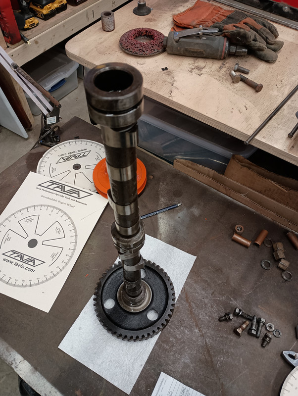
Guys, I escaped to the shop. Rolled the cam gear one tooth each direction. First rotated the cam gear one tooth clockwise the final degree number of the center-line of the intake lobe = 126 Next rotated the cam gear back past crank TDC mark one tooth counter clockwize. and the Lobe centerline final number was =96.
interesting that the math 126 + 96 = 222 divided by 2 = 111 humm!
So will need to cut a new keyway in the cam at the correct location I believe. More thinking on that location and dimension.
Regards, Chris and Cheryl
Edited by Sugarmaker - 16 Feb 2025 at 7:19pm
|
|
D17 1958 (NFE), WD45 1954 (NFE), WD 1952 (NFE), WD 1950 (WFE), Allis F-40 forklift, Allis CA, Allis D14, Ford Jubilee, Many IH Cub Cadets, 32 Ford Dump, 65 Comet.
|
|
steve(ill)
Orange Level Access
Joined: 11 Sep 2009
Location: illinois
Points: 90544
|
Post Options
Thanks(0)
Quote Reply
Posted: 16 Feb 2025 at 4:48pm |
|
Chris... i think im lost.. I though yesterday you got 111 and you wanted 105... I dont think you can just turn the crank to do this test.. I think you need to PULL the cam shaft out an inch, move ONE TOOTH so the timing marks are off by ONE TOOTH and then push back together ???? .... its just a TEST, but i THINK it is suppose to move 7.5 degrees so you should measure 111 - 7.5 = 103.5 ??
|
|
Like them all, but love the "B"s.
|
|
Les Kerf
Orange Level
Joined: 08 May 2020
Location: Idaho
Points: 1621
|
Post Options
Thanks(0)
Quote Reply
Posted: 16 Feb 2025 at 5:14pm |
Sugarmaker wrote:
...Les, Are you talking about when the valve just starts to open plus .050 on the indicator, then read the angle? |
... Yes. On the intake valve closing point you would read the degrees 0.050" before closing.
The reason I keep going back to this 0.050" thing is because that is the typical number that most modern cam grinders use to specify the effective duration (rather than Gross Duration, which is bigger).
If you can check the 0.050" duration, and if it comes anywhere near 197 degrees, then we will know that the cam grinder did actually use that number in the specs.
Then all you would need to do is get the intake to close (0.050") somewhere near 26 degrees ABDC and you will be where the cam is designed to run.
If he didn't use 0.050" then you need to determine what lift he did use (say, 0.006" or maybe 0.020") that corresponds to 197 degrees. Then you can use that number.
Closing the valve later will move the RPM range up, but may harm the low RPM torque. If you intend to run near stock RPM, then you don't want to close that valve very much later than the stock cam. Trouble is, I don't have that number.
|
|
Sugarmaker
Orange Level
Joined: 12 Jul 2013
Location: Albion PA
Points: 8647
|
Post Options
Thanks(0)
Quote Reply
Posted: 16 Feb 2025 at 7:46pm |
Folks,
I updated my words from my post above, from this afternoon to hopefully be more clear.
If you do a little math assuming my inspections are correct, you will see that moving the cam gear one tooth each way from the mark on the crank gear the new numbers are: 126 - 111 = 15 degrees exactly double the noted 7.5 expected degrees. 96 - 111 = 15 degrees exactly double the noted 7.5 expected degrees.
Based on this I believe the cam lobe center-line moves 15 degrees per cam gear tooth. I haven't thought through the logic but it may be because the cam gear turns 720 degrees or two times compared to one rev of the crank gear.
Again all this assumes I have done a fair job with the inspection.
Regards, Chris and Cheryl
|
|
D17 1958 (NFE), WD45 1954 (NFE), WD 1952 (NFE), WD 1950 (WFE), Allis F-40 forklift, Allis CA, Allis D14, Ford Jubilee, Many IH Cub Cadets, 32 Ford Dump, 65 Comet.
|
|
Sugarmaker
Orange Level
Joined: 12 Jul 2013
Location: Albion PA
Points: 8647
|
Post Options
Thanks(1)
Quote Reply
Posted: 16 Feb 2025 at 8:04pm |
Folks, i will work on finding the duration (197) More trials to do to find this and be repeatable.
I am using the plus and minus .050 inch from the top of the intake cam lobe to capture the degrees and then average them to get the lobe center-line. Seems to give good numbers.
Regards, Chris and Cheryl
Edited by Sugarmaker - 16 Feb 2025 at 9:37pm
|
|
D17 1958 (NFE), WD45 1954 (NFE), WD 1952 (NFE), WD 1950 (WFE), Allis F-40 forklift, Allis CA, Allis D14, Ford Jubilee, Many IH Cub Cadets, 32 Ford Dump, 65 Comet.
|
|
steve(ill)
Orange Level Access
Joined: 11 Sep 2009
Location: illinois
Points: 90544
|
Post Options
Thanks(0)
Quote Reply
Posted: 16 Feb 2025 at 8:31pm |
|
I think your right Chris... I was looking at it as leaving the CRANK at the right position and moving the CAM one tooth to get the lobe up.... I guess in reality ( a better way to think about it) is you are leaving the cam LOBE up , and moving the CRANK to a new positon... so that would be 15 degrees..... Im learning to, as i said, i have not really done this before..
Edited by steve(ill) - 16 Feb 2025 at 8:33pm
|
|
Like them all, but love the "B"s.
|
|
Sugarmaker
Orange Level
Joined: 12 Jul 2013
Location: Albion PA
Points: 8647
|
Post Options
Thanks(0)
Quote Reply
Posted: 16 Feb 2025 at 9:47pm |
Folks, The crank stayed at TDC and the cam lobe center-line moved CW or CCW one tooth. At its current keyed location in the cam gear the cams intake lobe is at 111 deg when the cam and crank are lined up on the marks. As you move the cam gear CW or CCW one cam gear tooth each way, the lobe moves advanced or retarded Approx 15 deg each way from the 111 on the degree wheel.
Regards, Chris and Cheryl
|
|
D17 1958 (NFE), WD45 1954 (NFE), WD 1952 (NFE), WD 1950 (WFE), Allis F-40 forklift, Allis CA, Allis D14, Ford Jubilee, Many IH Cub Cadets, 32 Ford Dump, 65 Comet.
|
|
Les Kerf
Orange Level
Joined: 08 May 2020
Location: Idaho
Points: 1621
|
Post Options
Thanks(0)
Quote Reply
Posted: 17 Feb 2025 at 7:15am |
Sugarmaker wrote:
...
Based on this I believe the cam lobe center-line moves 15 degrees per cam gear tooth. I haven't thought through the logic but it may be because the cam gear turns 720 degrees or two times compared to one rev of the crank gear... |
You are correct, I had a brain cramp 
You will probably need to have a new keyway cut unless an offset key can be made to take up that large of a difference.
|
|
Sugarmaker
Orange Level
Joined: 12 Jul 2013
Location: Albion PA
Points: 8647
|
Post Options
Thanks(0)
Quote Reply
Posted: 17 Feb 2025 at 1:06pm |
Guys, I have some of this backwards too. Couple things: The crank gear turns two rev and the cam gear turns 1 rev.
Did some noodling on the distance that the cam needs to move and the direction.
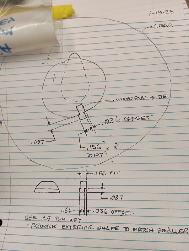
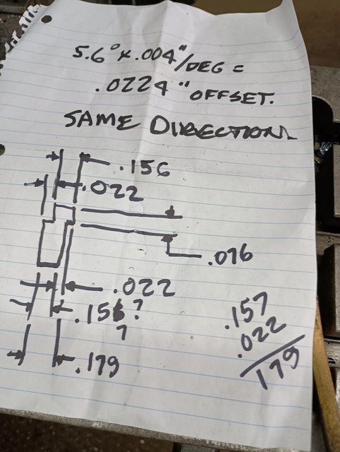
First the 105.4 degree spec minus 111 degree current lobe center line. = 5.6 degrees divide that in half (2.8 degrees) as the cam gear is twice as big so the 5.6 degrees as the point it comes to the cam gear is 2.8 deg of the circumference of the cam gear. Taking that 2.8 degrees back down to the size of the cam which is 1.5 inches. 2.8 degrees on the 1.5 inch dia =
I did some thinking and came up with a dimension of .036 actual movement in the cam inside the gear. That was based on the delta 5.6 angle divided by 2 = 2.8 deg on the cam gear at 1.50 dia so 1 degree on 1.5 = .013 inch. so .013 x 2.8 =.036 inches of cam movement. Fingers crossed!:)
Now we want the crank gear to come up to the 105 degree number sooner as it turns clockwise, the cam lobe needs to move to a position sooner as it turns counterclockwise. The lobe should move counter clockwise by the .036 inches.
I think I can get this movement with a custom built offset key.
Also I did take a quick check on the 197 degree number that Les was looking for. Turned the crank until I got to where the cam just started to move, went .050 inch beyond and read the wheel at -16 degrees. Spec says -9.3 continued to other side of the lobe went to where it stopped and backed up .050. read the wheel at 26 degrees. Right on spec at 26 ABDC so -16+26+180= 190. orig spec was 197 (-9.3+26+180 = 197) So off by 7 degrees? My inspection may need tuning??
Regards, Chris and Cheryl |
|
D17 1958 (NFE), WD45 1954 (NFE), WD 1952 (NFE), WD 1950 (WFE), Allis F-40 forklift, Allis CA, Allis D14, Ford Jubilee, Many IH Cub Cadets, 32 Ford Dump, 65 Comet.
|
|
Les Kerf
Orange Level
Joined: 08 May 2020
Location: Idaho
Points: 1621
|
Post Options
Thanks(0)
Quote Reply
Posted: 17 Feb 2025 at 10:17pm |
Sugarmaker wrote:
...Also I did take a quick check on the 197 degree number that Les was looking for. Turned the crank until I got to where the cam just started to move, went .050 inch beyond and read the wheel at -16 degrees. Spec says -9.3 continued to other side of the lobe went to where it stopped and backed up .050. read the wheel at 26 degrees. Right on spec at 26 ABDC so -16+26+180= 190. orig spec was 197 (-9.3+26+180 = 197) So off by 7 degrees? My inspection may need tuning??... |
Hmmm...
I hadn't planned on doing this yet, but the weather warmed up a bit today (39 degrees) so I went out to the shop and uncovered my combine engine (same as a Model C).
I checked the cam timing on cylinders #1 and #4 since the set up is the same. They were close enough to the same that will just report them as such.
Since my ancient Chilton's manual only specified the opening event at 0.010" I measured that as follows: Intake opens 0.010" @ 3 degrees ATDC Intake closes 0.010" @ 44 degrees ABDC for a Gross Duration of 221 degrees
I then checked the timing at 0.050" Intake opens 0.050" @ 22 degrees ATDC Intake closes 0.050" @ 28 degrees ABDC for a Net Duration of 186 degrees
It looks to me like you have the intake closing event pretty well nailed down the same as a stock cam, it just opens a lot sooner.
Try checking the exhaust events.
|
|
Sugarmaker
Orange Level
Joined: 12 Jul 2013
Location: Albion PA
Points: 8647
|
Post Options
Thanks(0)
Quote Reply
Posted: 18 Feb 2025 at 6:46pm |
Guys, I am going to get the offset key made in the next day or two. Decide to use a .25 wide key and trim it down to fit the keyways. That should be about .036 inch offset in the key moving the cam CCW from the cam gear.
I will have to check the exhaust angles after I get the cam back in.
Regards, Chris and Cheryl
Edited by Sugarmaker - 19 Feb 2025 at 9:02pm
|
|
D17 1958 (NFE), WD45 1954 (NFE), WD 1952 (NFE), WD 1950 (WFE), Allis F-40 forklift, Allis CA, Allis D14, Ford Jubilee, Many IH Cub Cadets, 32 Ford Dump, 65 Comet.
|
|
Sugarmaker
Orange Level
Joined: 12 Jul 2013
Location: Albion PA
Points: 8647
|
Post Options
Thanks(0)
Quote Reply
Posted: 19 Feb 2025 at 6:59pm |
Folks,
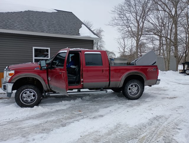
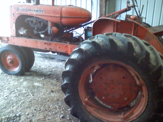
Off topic: Friend John K with our Ruby
Regards, Chris and Cheryl
|
|
D17 1958 (NFE), WD45 1954 (NFE), WD 1952 (NFE), WD 1950 (WFE), Allis F-40 forklift, Allis CA, Allis D14, Ford Jubilee, Many IH Cub Cadets, 32 Ford Dump, 65 Comet.
|
|
Les Kerf
Orange Level
Joined: 08 May 2020
Location: Idaho
Points: 1621
|
Post Options
Thanks(0)
Quote Reply
Posted: 19 Feb 2025 at 8:11pm |
Nice!  I do believe you are on the right track. Just looking at the picture the cam lobes do not appear to be as pointy as the cam in my B-125 Power Unit engine.
I made a new thread about that cam in case you missed it.
|
|
Sugarmaker
Orange Level
Joined: 12 Jul 2013
Location: Albion PA
Points: 8647
|
Post Options
Thanks(0)
Quote Reply
Posted: 19 Feb 2025 at 8:57pm |
Les, folks, Yes I saw your data in your post. Very good. Thanks guys for the tips and suggestions on my CA cam swap. I have learned new things engine related down in some details. I will not be an engine builder. Regards, Chris and Cheryl
Edited by Sugarmaker - 19 Feb 2025 at 9:00pm
|
|
D17 1958 (NFE), WD45 1954 (NFE), WD 1952 (NFE), WD 1950 (WFE), Allis F-40 forklift, Allis CA, Allis D14, Ford Jubilee, Many IH Cub Cadets, 32 Ford Dump, 65 Comet.
|
|
ekjdm14
Orange Level Access
Joined: 20 Aug 2024
Location: Alsager UK
Points: 987
|
Post Options
Thanks(0)
Quote Reply
Posted: 20 Feb 2025 at 6:37am |
Les Kerf wrote:
Nice! I do believe you are on the right track. Just looking at the picture the cam lobes do not appear to be as pointy as the cam in my B-125 Power Unit engine.
I made a new thread about that cam in case you missed it.
|
A cam with more duration will appear less pointy, kind of counter-intuitive but less "hump" = longer duration
I'm impressed by your dedication to get this thing running to it's fullest potential Chris. Interesting to note the "offset" on Les' camshaft. I wonder, if firing order is in fact an issue Allis had to work around why did they stick with 1243? And do any companies make a more "standard" 1342 cam for the 125 engine?
|
|
Les Kerf
Orange Level
Joined: 08 May 2020
Location: Idaho
Points: 1621
|
Post Options
Thanks(0)
Quote Reply
Posted: 20 Feb 2025 at 9:45am |
ekjdm14 wrote:
...A cam with more duration will appear less pointy, kind of counter-intuitive but less "hump" = longer duration |
Yup. More area under the curve. It's just simple calculus 
ekjdm14 wrote:
... And do any companies make a more "standard" 1342 cam for the 125 engine? |
I doubt it, this would be a VERY expensive cam to produce with its hollow bore, etc.
|
|
Sugarmaker
Orange Level
Joined: 12 Jul 2013
Location: Albion PA
Points: 8647
|
Post Options
Thanks(0)
Quote Reply
Posted: 20 Feb 2025 at 8:57pm |
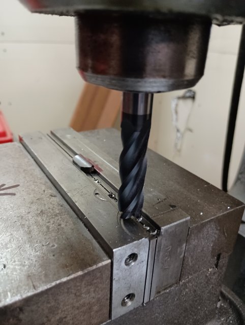
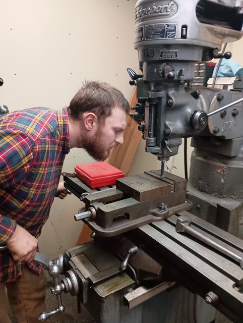
Guys, Friend Matt whittled out the offset key to my specs tonight. Assembly fit back together nicely.
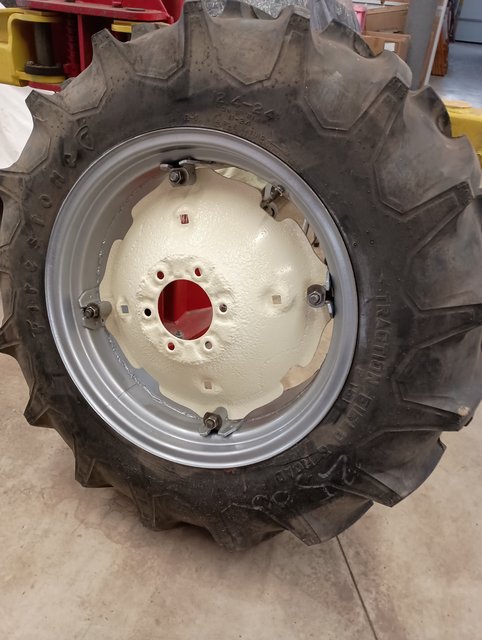
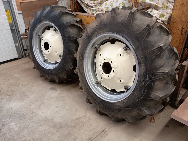
John came over today and helped put the centers in the CA wheels:
Small moves at snail pace. Weather has been cold. May get a slight break to start preparing to make maple syrup next week. We get some results on the cam movement results soon. Regards, Chris and Cheryl
|
|
D17 1958 (NFE), WD45 1954 (NFE), WD 1952 (NFE), WD 1950 (WFE), Allis F-40 forklift, Allis CA, Allis D14, Ford Jubilee, Many IH Cub Cadets, 32 Ford Dump, 65 Comet.
|
|
Les Kerf
Orange Level
Joined: 08 May 2020
Location: Idaho
Points: 1621
|
Post Options
Thanks(0)
Quote Reply
Posted: 21 Feb 2025 at 12:04am |
A friend with a Bridgeport is a friend indeed!
|
|
Les Kerf
Orange Level
Joined: 08 May 2020
Location: Idaho
Points: 1621
|
Post Options
Thanks(0)
Quote Reply
Posted: 21 Feb 2025 at 9:23am |
Any chance of having you do another camshaft check at 0.010" lifter rise on both intake and exhaust so I can compare it with mine? My curiosity is killing me
|
|
Sugarmaker
Orange Level
Joined: 12 Jul 2013
Location: Albion PA
Points: 8647
|
Post Options
Thanks(1)
Quote Reply
Posted: 21 Feb 2025 at 8:09pm |
Les, I have the cam in the engine. Need to get some time to start the process of inspection again.
Regards, Chris and Cheryl
|
|
D17 1958 (NFE), WD45 1954 (NFE), WD 1952 (NFE), WD 1950 (WFE), Allis F-40 forklift, Allis CA, Allis D14, Ford Jubilee, Many IH Cub Cadets, 32 Ford Dump, 65 Comet.
|
|
steve(ill)
Orange Level Access
Joined: 11 Sep 2009
Location: illinois
Points: 90544
|
Post Options
Thanks(0)
Quote Reply
Posted: 21 Feb 2025 at 9:12pm |
|
would be interesting to see if the lobes on #2 and 3 match the grind on #1 and 4... realizing your cam has been "modified"...
|
|
Like them all, but love the "B"s.
|
|
Sugarmaker
Orange Level
Joined: 12 Jul 2013
Location: Albion PA
Points: 8647
|
Post Options
Thanks(0)
Quote Reply
Posted: 23 Feb 2025 at 7:04pm |
Guys, I did get a chance to check the centerline angle of the lobe. A couple of times checking and I got 102 degrees. Which means I went too far and need lees of a offset. May have another key machined at about .024 or .026. (about 2 degrees) Will see if my friend Matt can do this for me again. Might coast me a a case of some frosty adult beverage.
Regards, Chris and Cheryl
Edited by Sugarmaker - 23 Feb 2025 at 7:11pm
|
|
D17 1958 (NFE), WD45 1954 (NFE), WD 1952 (NFE), WD 1950 (WFE), Allis F-40 forklift, Allis CA, Allis D14, Ford Jubilee, Many IH Cub Cadets, 32 Ford Dump, 65 Comet.
|
|
Sugarmaker
Orange Level
Joined: 12 Jul 2013
Location: Albion PA
Points: 8647
|
Post Options
Thanks(0)
Quote Reply
Posted: 01 Mar 2025 at 7:20am |
Folkd. Maple syrup production is starting and taking most of our time. The little Allis engine waits for a new offset key to be made for the cam to cam gear. Regards, Chris and Cheryl
|
|
D17 1958 (NFE), WD45 1954 (NFE), WD 1952 (NFE), WD 1950 (WFE), Allis F-40 forklift, Allis CA, Allis D14, Ford Jubilee, Many IH Cub Cadets, 32 Ford Dump, 65 Comet.
|
|
Sugarmaker
Orange Level
Joined: 12 Jul 2013
Location: Albion PA
Points: 8647
|
Post Options
Thanks(1)
Quote Reply
Posted: 02 Mar 2025 at 3:12pm |
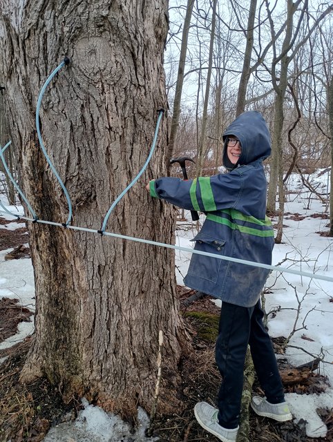
Allis folks, I have excuses all the time! Getting ready to tap the sugarbush a couple weeks ago. Cheryl has been riding along with me for hours at a time getting set up and tapped. We only have a small syrup hobby business, about 625 taps.
Family is helping. Great grandson helping tap the last 200 taps:
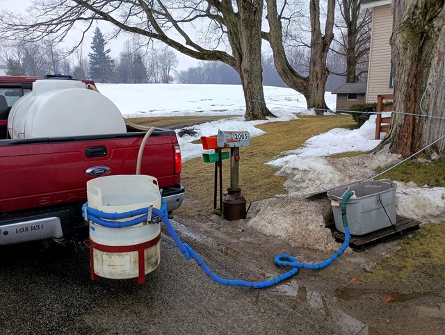
Gathering sap:
What I do best, rest!
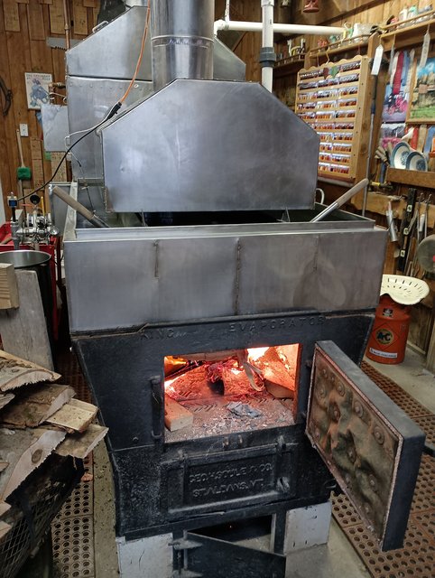
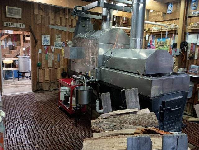
Grandson Mike helping get started with our first boil of 2025:
The old school wood fire in the arch warms the bones:
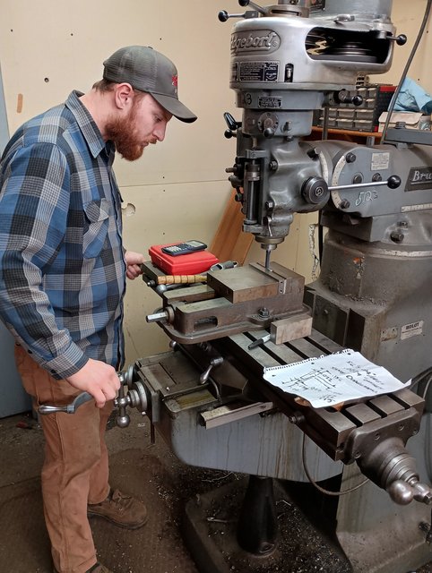
Back to the real world and the old Allis cam:
Matt using his skills to mill a new key:
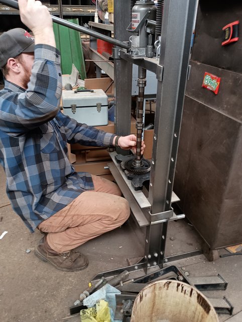
Cam gear and shaft re assembled:
Regards, Chris and Cheryl
Edited by Sugarmaker - 02 Mar 2025 at 3:20pm
|
|
D17 1958 (NFE), WD45 1954 (NFE), WD 1952 (NFE), WD 1950 (WFE), Allis F-40 forklift, Allis CA, Allis D14, Ford Jubilee, Many IH Cub Cadets, 32 Ford Dump, 65 Comet.
|
|
tadams(OH)
Orange Level Access

Joined: 17 Sep 2009
Location: Jeromesville, O
Points: 11381
|
Post Options
Thanks(0)
Quote Reply
Posted: 03 Mar 2025 at 2:18pm |
Keep the fire going and the syrup boiling, enjoy. Tom
|
|
Sugarmaker
Orange Level
Joined: 12 Jul 2013
Location: Albion PA
Points: 8647
|
Post Options
Thanks(1)
Quote Reply
Posted: 03 Mar 2025 at 7:01pm |
Allis folks, I installed the cam in the CA engine. Set it up for inspection of the lobe center-line again. Checked it several times and found the numbers to be consistent at 106 degrees. The spec was 105.4 IIRC. So this is very close to the cam card and it will be close enough to allow me to carry on with the rest of the build. I will try to check the rest of the cam lobes if I get a chance. Regards, Chris and Cheryl
|
|
D17 1958 (NFE), WD45 1954 (NFE), WD 1952 (NFE), WD 1950 (WFE), Allis F-40 forklift, Allis CA, Allis D14, Ford Jubilee, Many IH Cub Cadets, 32 Ford Dump, 65 Comet.
|
|
Les Kerf
Orange Level
Joined: 08 May 2020
Location: Idaho
Points: 1621
|
Post Options
Thanks(1)
Quote Reply
Posted: 03 Mar 2025 at 8:24pm |
Sugarmaker wrote:
Allis folks, I installed the cam in the CA engine. Set it up for inspection of the lobe center-line again. Checked it several times and found the numbers to be consistent at 106 degrees. The spec was 105.4 IIRC. So this is very close to the cam card and it will be close enough to allow me to carry on with the rest of the build. I will try to check the rest of the cam lobes if I get a chance. Regards, Chris and Cheryl |
Sweet! And thank you for the wonderful photos of your sugaring operation.
|
|
Sugarmaker
Orange Level
Joined: 12 Jul 2013
Location: Albion PA
Points: 8647
|
Post Options
Thanks(0)
Quote Reply
Posted: 08 Mar 2025 at 8:56am |
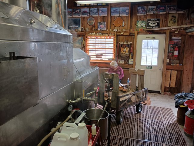
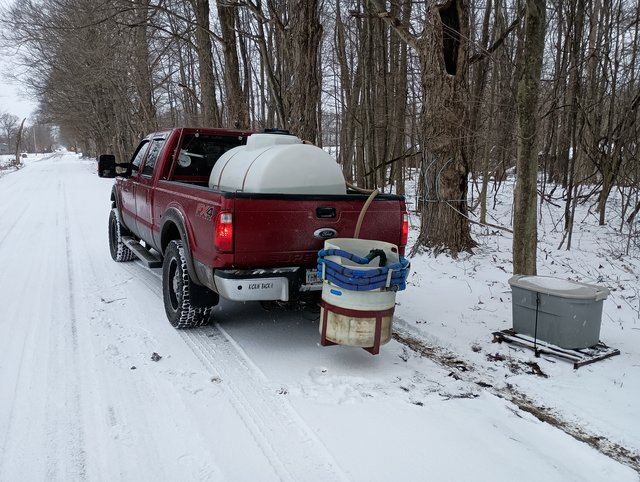
Les, Allis folks, Way off topic but we are into our maple syrup season. I will post a bunch of pictures that may be of interest to some folks. My toy:
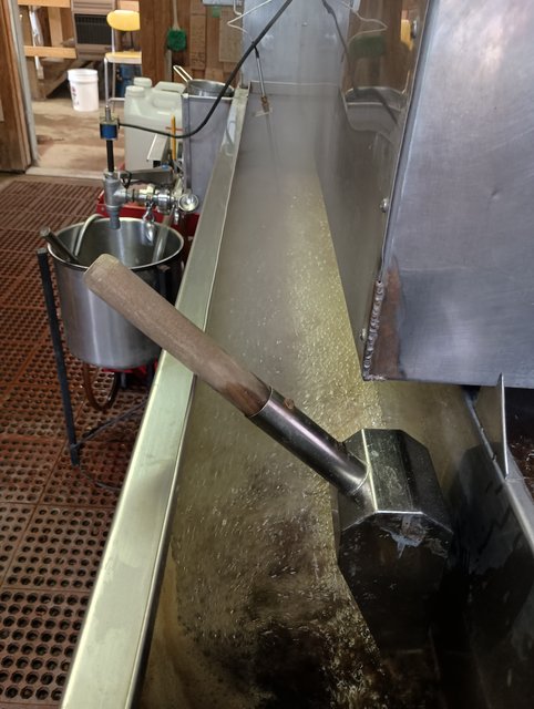
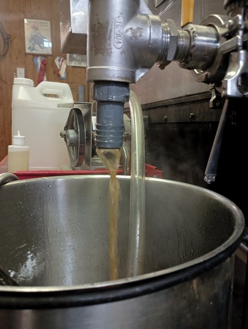
Almost syrup:
There is some of the first syrup for 2025 a nice amber, great flavor:
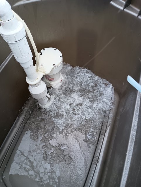
Gathering sap and we have some ice in the collection containers:
Cheryl is trying to stay warm in the cool sugar house. Ruby by her side most of the time:
This was the snow a couple days ago. Dropped just below freezing last night again and another 2 inches of snow this morning.
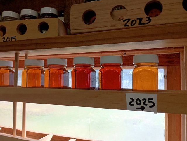
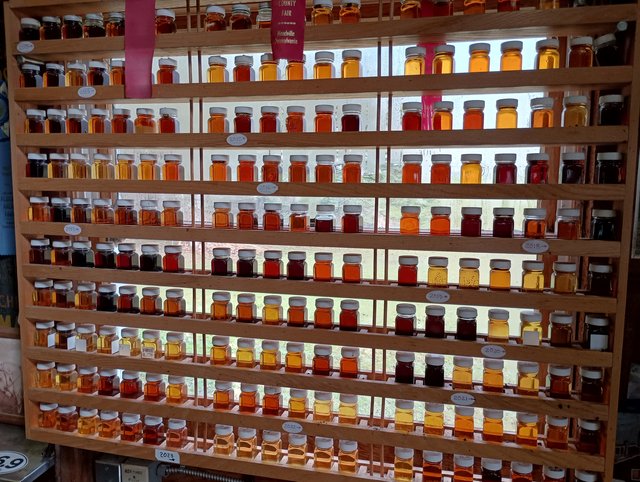
Samples of our syrup from 24 years in our sugar house. Two windows are full not sure I will fill a third window. We make about 10-20 samples per year. Getting too old for this!
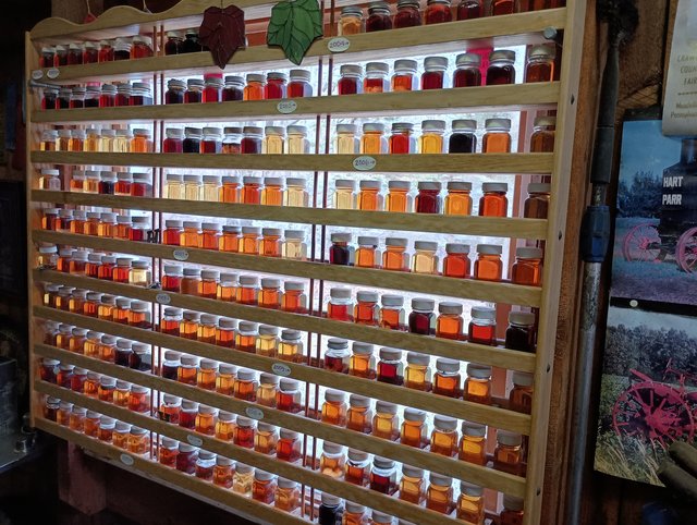
Here is the other display in the window.
Regards, Chris and Cheryl
Edited by Sugarmaker - 08 Mar 2025 at 8:57am
|
|
D17 1958 (NFE), WD45 1954 (NFE), WD 1952 (NFE), WD 1950 (WFE), Allis F-40 forklift, Allis CA, Allis D14, Ford Jubilee, Many IH Cub Cadets, 32 Ford Dump, 65 Comet.
|
|


 Topic Options