| Author |
 Topic Search Topic Search  Topic Options Topic Options
|
steve(ill) 
Orange Level Access


Joined: 11 Sep 2009
Location: illinois
Points: 88632
|
 Post Options Post Options
") Thanks(0) Thanks(0)
") Quote Quote  Reply Reply
 Posted: 29 Jan 2025 at 10:21pm Posted: 29 Jan 2025 at 10:21pm |
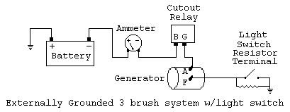
A CUTOUT was original... It has two wires.. the "A" goes to the relay - then amp meter and the "F" is the GROUND WIRE that goes to the light switch resistor.... If you had a VOLTAGE REGULATOR, you would not need the light switch resistor and the reg would have 3 wires..
Edited by steve(ill) - 29 Jan 2025 at 10:24pm
|
|
Like them all, but love the "B"s.
|
 |
|
Sponsored Links
|
|
|
steve(ill)
Orange Level Access
Joined: 11 Sep 2009
Location: illinois
Points: 88632
|
Post Options
Thanks(0)
Quote Reply
Posted: 29 Jan 2025 at 10:29pm |
|
wire #9 in the drawing looks like a HOT WIRE from the amp gauge to the distributor / mag.... that wire is NOT NEEDED on the magneto... The Mag only needs a GROUND SWITCH to kill the spark... the HOT WIRE is needed for a distributor since it is Battery Ignition with a COIL and POINT..
Edited by steve(ill) - 29 Jan 2025 at 10:30pm
|
|
Like them all, but love the "B"s.
|
|
Les Kerf
Orange Level
Joined: 08 May 2020
Location: Idaho
Points: 1396
|
Post Options
Thanks(0)
Quote Reply
Posted: 30 Jan 2025 at 9:05am |
 pudi211 wrote: pudi211 wrote:
Looking at the above photo I posted, you can see the previous owner had a wire going to the voltage regulator or cut out (still not sure what I have)... |
Looks like a cutout to me
pudi211 wrote:
... He then had a jumper going to the A terminal... |
If that jumper is connecting the A terminal to the F terminal this is not good. I cannot see it clearly enough in the photo to be sure.
pudi211 wrote:
...and he had two wires going to the F terminal... |
Dunno where the two wires go but this cannot be good either. There needs to be only one wire going to the light switch for controlling the field current.
pudi211 wrote:
None of this lined up with the wiring diagram... |
The diagram posted by Steve is correct for a stock application.
Edited by Les Kerf - 30 Jan 2025 at 9:18am
|
|
pudi211
Bronze Level

Joined: 02 Sep 2023
Location: Delaware
Points: 36
|
Post Options
Thanks(0)
Quote Reply
Posted: 30 Jan 2025 at 8:14pm |
|
Thanks Steve. You've been helpful through this process.
|
|
pudi211
Bronze Level
Joined: 02 Sep 2023
Location: Delaware
Points: 36
|
Post Options
Thanks(0)
Quote Reply
Posted: 30 Jan 2025 at 8:17pm |
Yeah the jumper was connecting the cutout to the A terminal. The wiring was a complete mess. Tractor does not have lights, the belt was shredded and it was wired for negative ground. I'm just trying to take it back to the original.
I should be good from here. I still need to rebuild the generator. That should be pretty straight forward if it's anything like rebuilding a starter.
Edited by pudi211 - 30 Jan 2025 at 8:20pm
|
|
steve(ill)
Orange Level Access
Joined: 11 Sep 2009
Location: illinois
Points: 88632
|
Post Options
Thanks(0)
Quote Reply
Posted: 31 Jan 2025 at 8:03am |
|
are you using the OLD Cutout ? ..... It is basically an ON- OFF switch... the two terminals should be OPEN ( no continuity between them) when the motor is OFF and the switch will CLOSE and allow generator current / voltage to go to the amp meter when the motor is RUNNING.
|
|
Like them all, but love the "B"s.
|
|
pudi211
Bronze Level
Joined: 02 Sep 2023
Location: Delaware
Points: 36
|
Post Options
Thanks(0)
Quote Reply
Posted: 31 Jan 2025 at 4:37pm |
|
Hi Steve, I do plan on using the old cutout assuming it works. Assuming it works like an on/off I should see voltage on the terminals with the tractor running? I can tell you that I bench tested the generator and well, it didn’t generate. Goal is to rebuild it and go from there.
|
|
pudi211
Bronze Level
Joined: 02 Sep 2023
Location: Delaware
Points: 36
|
Post Options
Thanks(0)
Quote Reply
Posted: 10 Feb 2025 at 7:39pm |
|
Well, the good news is I got the CA running. In a Hail Mary attempt, I hooked up a 12v battery and got it running , set the timing and tuned the carb. I’m going to rebuild the generator now. Hopefully will get that back in working order.
|
|