Adding a "new" loader & live hydraulics to my D17
Printed From: Unofficial Allis
Category: Allis Chalmers
Forum Name: Farm Equipment
Forum Description: everything about Allis-Chalmers farm equipment
URL: https://www.allischalmers.com/forum/forum_posts.asp?TID=187920
Printed Date: 02 Apr 2026 at 1:29am
Software Version: Web Wiz Forums 11.10 - http://www.webwizforums.com
Topic: Adding a "new" loader & live hydraulics to my D17
Posted By: Morpar55
Subject: Adding a "new" loader & live hydraulics to my D17
Date Posted: 28 Apr 2022 at 9:12am
|
In the years since I inherited my Dad's D17 I have used the factory loader quite a bit, but never really been happy with it. First off before I got the tractor some dummy (me) was using the tractor to try and dig some dirt and managed to tweak something so the bucket no longer sat flat on the ground. Plus the trip bucket system has been problematic when trying to pick up anything with significant weight to it. I thought about adding a cylinder or 2 to curl the bucket, but then ran into the whole issue of the series 1 not having live hydraulics. After joining this forum and doing a LOT of research I put together a plan to add live hydraulics using a front mount pump and decided I would be time and money ahead to find a complete front loader to fit to my tractor. The loader I found was an old Freeman 4000 series loader which had been on a Farmall 560 according to the seller. The measurements I took from my tractor lined up almost perfectly with this loader, so after a bit of haggling we loaded it on the trailer and brought it home. 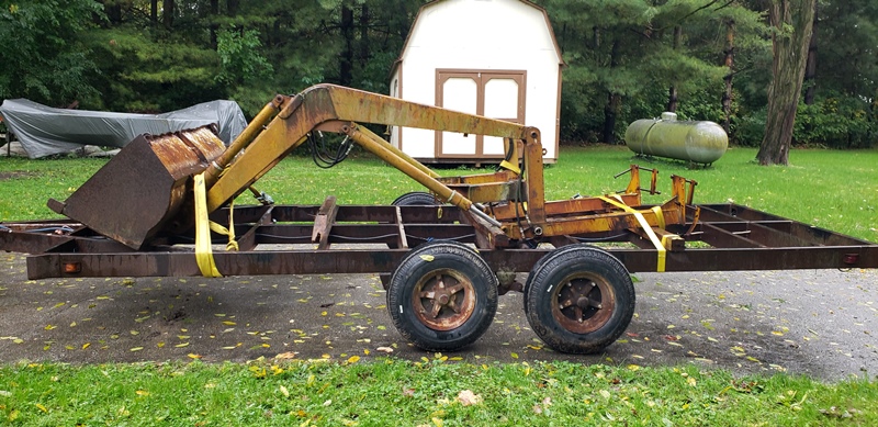 I finally got to the point of starting this project last week so I got this dragged into the shop (minus the bucket) and torn down a bit to do some repair work. I found there had been some booger welds done on the mounting brackets for this loader, and before I put them on the tractor they would be easier to repair. The right side bracket thus far is the worst. 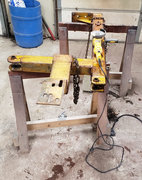 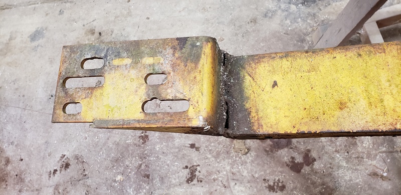 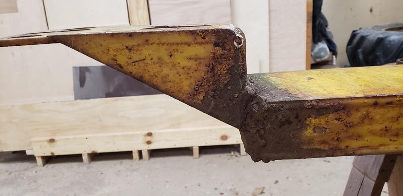 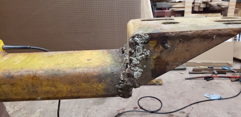 Next up will be starting the repairs by removing parts! ------------- 1959 AC D17 Gas with some updates |
Replies:
Posted By: FloydKS
Date Posted: 28 Apr 2022 at 10:37am
|
Looks like you are having fun fixing what someone "tried to start" ... hope it is going as you hoped it would. ------------- Holding a grudge is like taking poison and expecting the other person to die |
Posted By: Morpar55
Date Posted: 28 Apr 2022 at 12:30pm
|
Fun is a subjective term, but definitely satisfying! My Dad taught me early on to do what you don't really want to do or what looks the hardest first in a project and things SHOULD smooth out from there. For the most part he was right, so I started off by cutting off the mounting ear for the right side mount. One side was pretty easy, as there wasn't much holding it, and the short edges of the tubing were pretty easy too. The bottom side had ugly but solid weld and was holding tight. Once I got the cutting off and cleaning up of the tubing and the bracket done I had this: 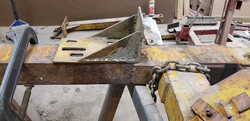 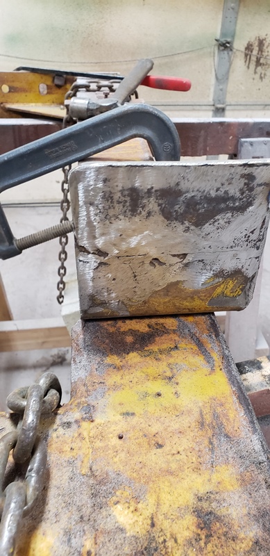 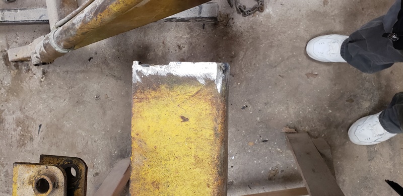 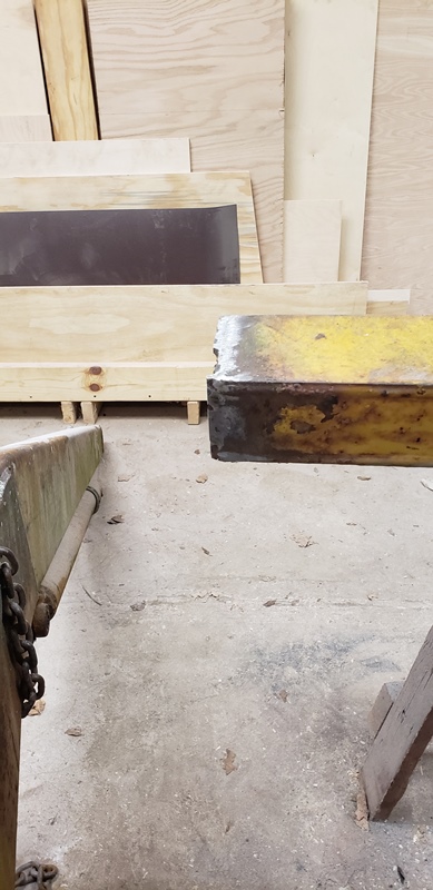 The end of the tubing is something other than straight or square and I plan to mark it so it is and then fire up the cut-off wheel to make it nice and ready to weld the mounting bracket back on. I know this will effectively move the mounting bracket further back (in reference to the rear axle) on this side, but when I looked before there should be enough room in the slots to accommodate this. The mounting bracket itself will need a little more work first. As I was cleaning it up I found a crack going through it. It seems to start at the edge where the gusset iss welded on and is making it's way more towards the center. 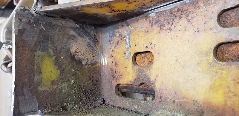 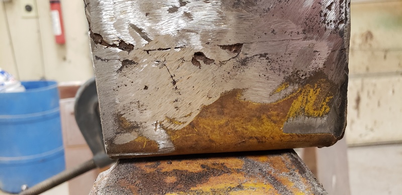 I plan to clean the side up more in the bottom picture (calling this the inside) to make the crack more visible, then drill a small hole to stop the crack, grind out the face of the crack, then weld it up. Once done I will need to grind part of the crack repair weld down where the bracket mates up with the tubing OR notch the tubing for the weld. Any opinions on how to handle that? I'm not sure if either method will make a difference on how the crack repair will last in the long term. I have a friend here at work who is actually a weld engineer, so I think I will ask him his opinion as well. I also plan to add some gusseting going from the bracket to the tubing, but I need to make sure the pieces are assembled well beforehand. Hopefully I can find a little time to work on this over the weekend! ------------- 1959 AC D17 Gas with some updates |
Posted By: Morpar55
Date Posted: 22 May 2022 at 1:07pm
We have had some family issues going on, so I haven't had much time to work on the loader project or post what I have done. I will try to remedy that starting today! I also neglected to get any pictures of the repairs I made to the cracked mounting bracket, but it was repaired before welding back on to the mounting arm. But before I made the repair the end of the tubing was cut off square, as it was in pretty bad shape when I started.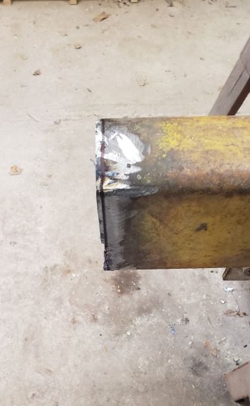 I marked a line all the way around and used a cut off wheel to make a nice straight line. Next up I aligned the mounting foot and welded it on. This took me a little time, as I didn't tack the pieces together the way I should have and had to "persuade" the bracket to be up tight against the tubing all around. Once I got it all tacked I ended up running 2 good passes to secure everything. 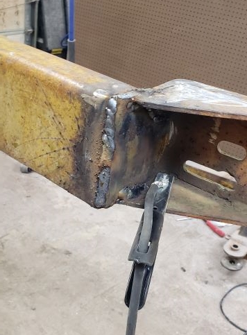 The next step was to start adding the gusseting. Why this was built this way originally without a gusset I don't know, but 4 pieces of 3" angle iron 6" long does a good job. And yes, I know the one weld on the right side looks bad. I was having trouble with my helmet and kind of wandered away from where I wanted to weld! That helmet was officially retired later that day. 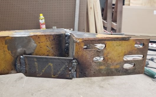 Looking at it from the bottom better shows the position of the gusset. 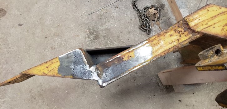 This was my stopping point for one day. I also checked and found out I would need to trim one side of the angle down, as the tubing is a little under 6" wide. I was still pleased with what I got done in just a couple of hours. ------------- 1959 AC D17 Gas with some updates |
Posted By: Morpar55
Date Posted: 22 May 2022 at 1:44pm
Only 2 more things to add and repair and the right mounting arm is done! Hopefully next week I can start getting all of these pieces installed and see if it will work. After cutting a little over 1/8" off one side of the 3" angle and also making an angle cut on a corner the remaining part of the gusset was ready to add. 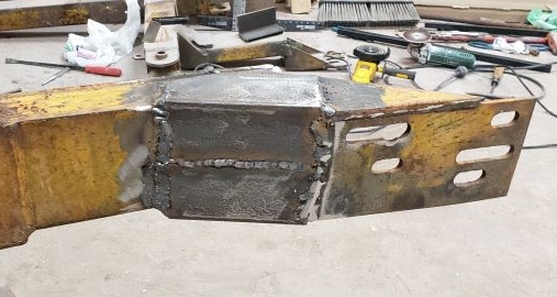 Last but not least there are 2 tabs on the bottom of the mounting arms. These appear to be for some sort of spacers, so I welded the tab back on just in case it is needed. 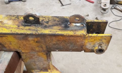 Once this was all done the right arm is ready for install. I'm not going to paint anything until I see what other changes I need to make. Once I set this arm aside and started checking out the left arm I found a lot of the same problems. Not so much the booger repair welds, but some cracking. I ended up making the same repairs to the left side as I did the right side. So once I get some space back in the shop (I have another project using up space right now) I can get the tractor in and start getting these pieces mounted up. ------------- 1959 AC D17 Gas with some updates |
Posted By: DaveKamp
Date Posted: 22 May 2022 at 10:54pm
|
The tricky thing about making loader brackets, is getting the location, position, angle, etc., all correct. Best way I've found to accomplish that, is to bolt the brackets to frame accordingly, then bring the rest of the framework into position, and adjust it until the geometry of everything is as close to 'proper' as you can. Sometimes this will reveal that a bracket isn't wide enough, or too wide, or one is more forward that the other or the loader frame is 'offset' to one side... So I adjust until everything is square with the tractor, then I TACK weld everything in-situ. Then I disassemble, and finish weld. The 400 should work well for you. One can modify a trip-bucket, but there's some realities to the trip bucket setup that, when you attempt to convert to a full hydraulic, simply don't carry over. Most TB setups are single-acting... meaning, hydraulic boom lift, but gravity down. it is for this reason, that TB loaders generally don't 'dig' very well... not in comparison to a full hydraulic that will lift the tractor front end right off the ground. No offense to TB loaders, but without the bucket curl AND a full bidirectional circuit on the boom lift/lower, I dub them "Half a Loader". They're functional for what they intended, but comparing it to a 'full loader', they're just not as beastly effective.
------------- Ten Amendments, Ten Commandments, and one Golden Rule solve most every problem. Citrus hand-cleaner with Pumice does the rest. |
Posted By: Morpar55
Date Posted: 23 May 2022 at 6:31am
|
Since these main brackets needed repaired I wanted to get them fixed before installing (and possibly modifying) them. But what you are saying is the main plan I am using. Right now my biggest concern is clearance for the front mounted pump. I plan to get the loader roughly bolted up to the tractor and then install the pump and use the engine hoist to raise and lower the main loader frame and check for clearances. Then adjust as needed from there. With any luck at all I won't need to buy much steel, as the prices have shot up around here. ------------- 1959 AC D17 Gas with some updates |
Posted By: DaveKamp
Date Posted: 23 May 2022 at 4:29pm
|
that's a good plan. I've found that loader geometry works out about right when you set the machine atop some 2x6's flat on the shop floor, with bucket flat on the floor... that means your full-down offset is about 1.5"... but guys do it all sorts of ways. Pump clearance shouldn't be too big an issue, as if you have it that close to the grille, you probably won't have much forward 'reach' for dumping into a tall dumptruck. It's a tough balance, if you stretch it out too far forward, you wind up with too much ballast on back, and a machine that's too long to easily maneuver tight quarters. Front mounting the hyd pump isn't difficult... you'll need to fab a mounting plate for a standard (A, B, or C) face pump. I made a splined coupler for the front crank pulley, and made a stub shaft that had splines to fit the coupler, and splined socket at the other end for my pump. To make it, I found a piece of splined shaft long enough, then cut a long splined tube section to make the crank coupler (out of one half) and the shaft extension coupling (to the pump) out the other. I put the pieces together in-situ, then measured the amount of space off-the-front, to clear the hard parts. I used the holes on front nose casting to bolt on the pump bracket, and I put about an eighth-of-an-inch extra distance on the bracket standoffs, so that the pump shaft wouldn't 'bottom' in the coupler in any way. But having built it all, I haven't managed to get it installed yet... probably because I was seriously considering applying it to a different project tractor instead....  ------------- Ten Amendments, Ten Commandments, and one Golden Rule solve most every problem. Citrus hand-cleaner with Pumice does the rest. |
Posted By: Morpar55
Date Posted: 26 May 2022 at 5:47am
I am using the front mount kit from A&W Tractors on this project for the live hydraulic pump, and so far things have fit like a glove! Yesterday I had a few hours open and pulled the trigger all the way on this project. Just to show how bad things were tweaked here is a before picture.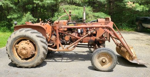 There is a good 3" worth of space between the right front corner of the bucket and the ground, and the left side is touching on fairly flat blacktop. Once the loader was removed I took off the cylinders before putting the tractor in the shop. If anyone needs a set of cylinders (or other parts for the old loader) message me and I will make you a sweet deal! Otherwise my first test with the new loader will be to put the old loader in the back of the truck for a trip to the scrap yard. 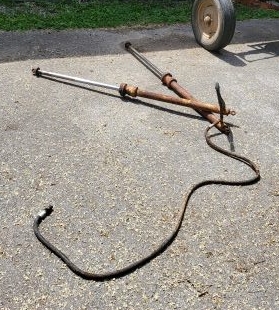 Once I got into the shop and all of the old mounting hardware removed I put my "new" brackets in place and started mocking things up. I used much smaller pins just to see if the loader frame would fit, clear, and move the way I think it should. Fortunately it did! 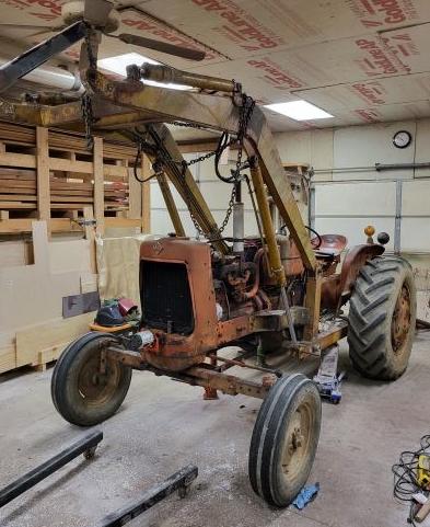 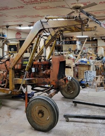 At this point I took a little break, since I couldn't believe things were working out so far! Probably should have went out for a lottery ticket, but oh well! When I lifted the loader frame up I did check frame to pump clearance and was pleasantly surprised with about 3 1/2" of space right now. 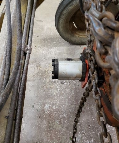 I will likely need to shift the mounting brackets rearward anyway, but I still have room to add some kind of guard for the pump. When I bolted the mounting brackets to the tractor frame I used the original front hole just as a starting point. I think I will use the lower set of slots in these mounting brackets, as right now there is PLENTY of cylinder stroke left for down pressure. 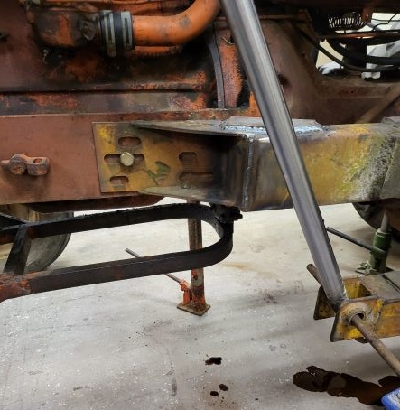 Even at full up inside the shop I have more stroke for the loader to come up, so I think I will be good both directions. 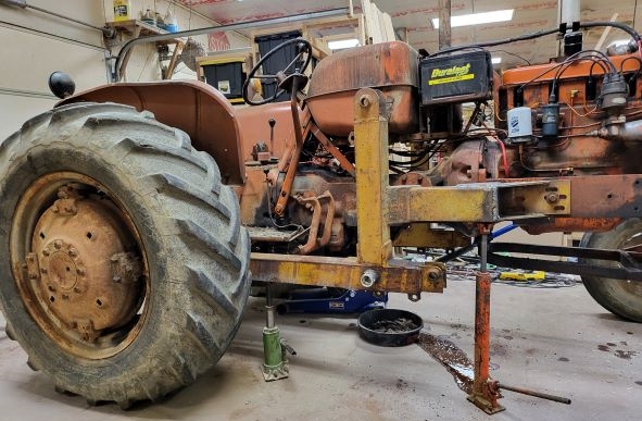 I still need to work out how to attach the mounting brackets to the rear axle, as the current mounting plate on the loader brackets will not work. I may have to add some kind of step too for getting up into the seat easier, but one thing at a time! ------------- 1959 AC D17 Gas with some updates |
Posted By: Morpar55
Date Posted: 30 May 2022 at 6:31pm
For some reason the place I normally buy steel from decided they wanted to make Memorial Day weekend a 4-day weekend. So rude! Anyway, since I couldn't go buy steel I still tried to move forward. On Friday I worked on getting the mounting arms square and level in relation to the tractor. Turns out I didn't exactly weld up the mounting arms as well as I should have....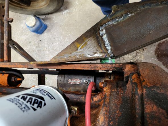 On the right side I completely missed keeping the mounting foot parallel to the frame. And not just a little, almost 3/8 of an inch! Yeah, that was a moron (spelled dumb-a55) attack on my part. At least this side is almost perfectly plumb. The left side needed a little bit of a shim on the bottom side to be plumb. I also needed to move the right side mounting bracket back about 3/8" and the left side forward the same amount I had to modify the mounting slots. It's worth noting I also used the bottom set of mounting slots after my initial proof of concept since there is lots of room for the cylinders to stroke. 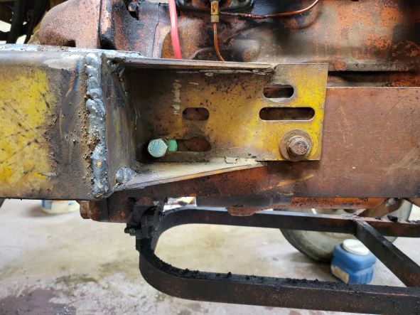 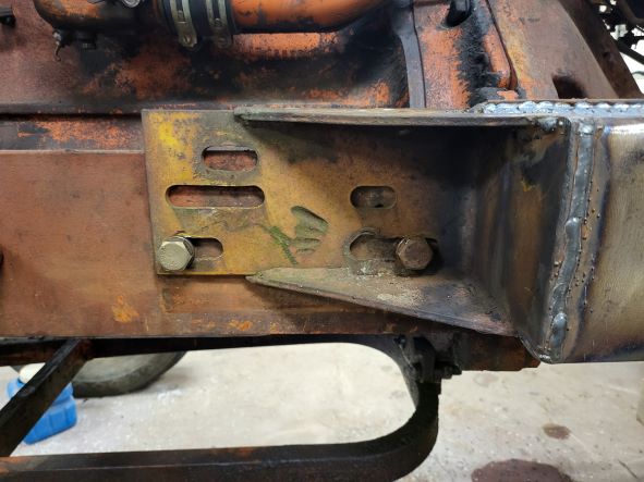 Last but not least for the day I got the rear tires and wheels off the tractor without squishing myself. The left wheel has a roughly 8" section of the rim rusted away, and I have much better set of replacements. 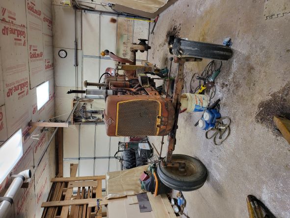 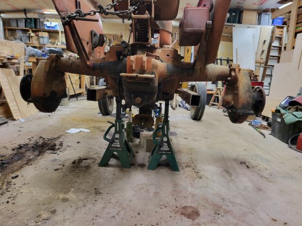 ------------- 1959 AC D17 Gas with some updates |
Posted By: Morpar55
Date Posted: 30 May 2022 at 7:08pm
For my Memorial Day update I tried to get my steel order ready for tomorrow morning. Everyone who is an old car guy will understand the term "slapper bars" when it comes to the rear suspension. While a D17 doesn't have to deal with spring windup during launch like an old Camaro, Nova, or Firebird does, the idea held over for me. I figure when the bucket is loaded down if the loader framework is touching the bottom of the rear axle things will be the most stable. Plus I can mount everything using U-bolts too. I made a design kind of like the old slapper bars and then made my steel shopping list for in the morning. Afterwards I worked on putting some of the remaining parts on the tractor I left off from last fall.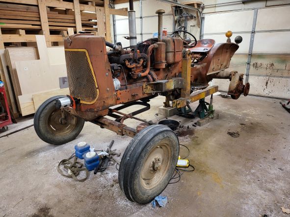 Basically the side panels and the hydraulic pump got bolted on this afternoon plus the gas tank strap.  I was going to bolt the piece across the top back on (from the gas tank to the radiator), but found out I somehow lost one of the 3/8" fine-thread bolts for the front end. Another "Moron moment"! I guess I will have to see if I can get a new one when I am in town in the morning. I also need to get smaller headlights as the ones originally on the tractor won't clear the new loader. Rural King and/or Tractor Supply will love me! 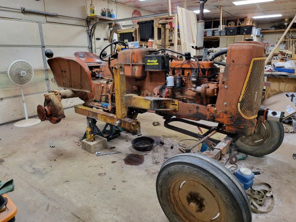 When I bolted up the front pump I found a slight interference too. The hydraulic pump felt like the driveshaft going to the adapter on the crankshaft was pushing the pump away from the front of the tractor. I can't really describe it, but something felt off and the old maintenance guy in me said to stop and investigate! I am glad I did, as while it would probably work for a while I have no desire to tear up a pump. I'm kind of cheap in the grand scheme of things! I ended up moving the shaft forward into the space between the chain coupling halves and then cutting about 1/8" off the engine side of the shaft too. Everything has room to move now without loading the pump, and if for some reason the shaft needs to move back it still can. ------------- 1959 AC D17 Gas with some updates |
Posted By: PaulB
Date Posted: 30 May 2022 at 7:41pm
|
Move the headlights to the rear fenders or I've seen plenty of Frog Eyes by putting the headlights on the top of the radiator shell. ------------- If it was fun to pull in LOW gear, I could have a John Deere. Real pullers don't have speed limits. If you can't make it GO... make it SHINY |
Posted By: Clay
Date Posted: 30 May 2022 at 9:34pm
|
Here is a bit of advise you should seriously consider....Perform and engine tune up BEFORE you install the loader frame. Why, you ask. Simple. The loader frame makes it almost impossible to look into the hole where the timing marks are viewed. The timing marks are viewed from the side hole in the area where the engine clutch housing meet.
|
Posted By: Morpar55
Date Posted: 06 Jun 2022 at 7:19pm
I got a little busy doing lots of things including getting a new washer and drier and adding an electrical circuit in the house for the washer. I did manage to keep doing some work on the loader project though. For this post I will cover what I got done on June 1st and 2nd. On the first I went shopping. I needed to get some steel, some custom U-bolts, the potential new headlights, and some hardware. The steel and the U-bolts were the pricey part of the day.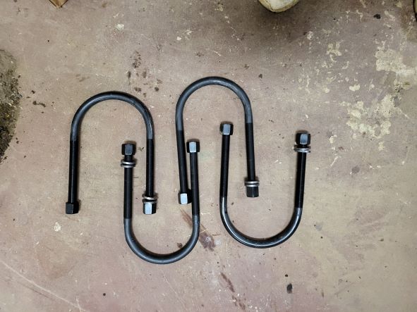 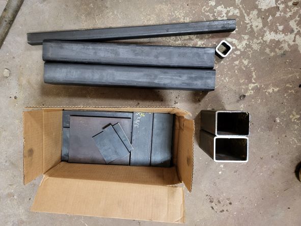 There is a shop which does repair work for semis, and they also make custom U-bolts. I had 2 U-bolts made to fit around a 6" diameter axle tube and 2 more made for 5 1/2". These U-bolts are 3/4" diameter and come with heavy-duty hardened washers and long nuts. While checking to see if I had made a costly mistake with the size for the U-bolts I found a date stamp on the axle housing casting which interfered. A couple of minutes with the grinder took care of that! I checked the left side while I was at it and removed that one too. 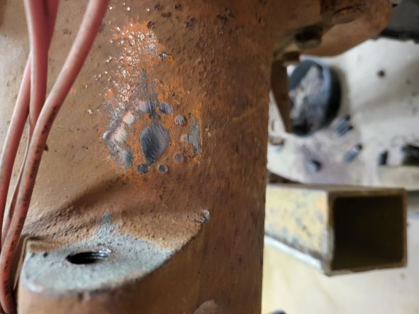 There is a cast boss on the top of the housing which I am using to locate the 6" U-bolt. It keeps the U-bolt from moving outward, and the taper of the axle housing won't let it move inward. 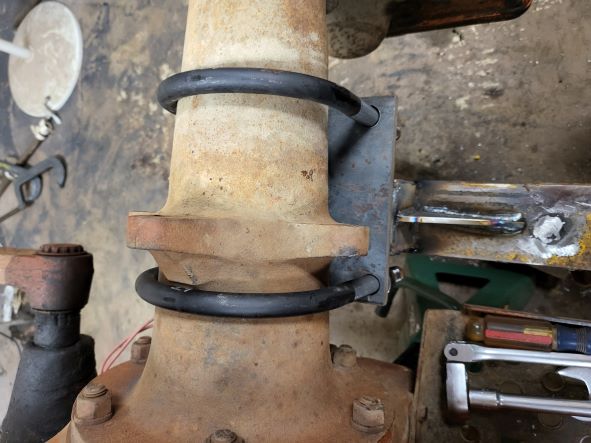 Yes, this picture seems to be from the left side. I forgot to take a picture of this location on Tuesday, so I did it today! The inner U-bolt is pretty much stuck in this location due to the shape of the axle housing casting. Next I placed the 3" square tubing I bought to go inside my mounting framework on top of the tube and put the axle mounting plate and U-bolts in place to determine how far in the 3" tubing would go. 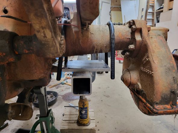 The axle mounting plate is an 8" x 8 1/4" piece of 1/2" steel. I laid out and drilled the 13/16" holes to match the appropriate U-bolt size. 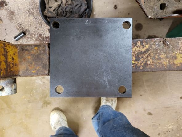 Once I had a length I started making the 3" tubing a little narrower where it was going to fit inside the framework. I did this with a grinder for the right side, but I had the left side tube milled so I wouldn't spend nearly 2 hours grinding off 1/16" on each side! Once I had the inner tubing to where it would slide in I drilled and tapped a 3/8" coarse hole about 2" in from the end so I could pull the front of the tube up and plug weld it. I drilled 3/4" holes in the outer tubing for plug welds. 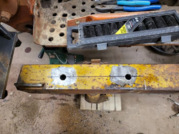 I used a couple of 3/8" fender washers and a bolt to pull the front of the inner tube up to the top of the outer tube, and used a clamp in the rear to position for welding. Once I was happy with everything I plug welded the center hole, tacked the tubing together in the rear, removed the bolt (saving it for the other side), and plug welded the front. 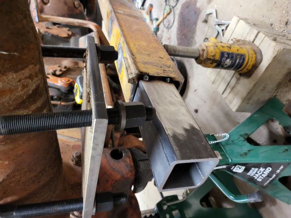 I also took this opportunity to tack weld the 5/8" collars to the front mounting brackets. My thinking is this should put the stresses of using the loader on a wider area of the bolt and avoid cutting grooves on them as I have seen on other equipment. 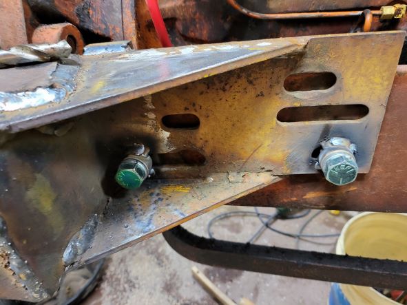 Once I took the right side mounting frame off for welding I took the time to notch the 3" x 4" tubing to clear the outer tubing on the frame. 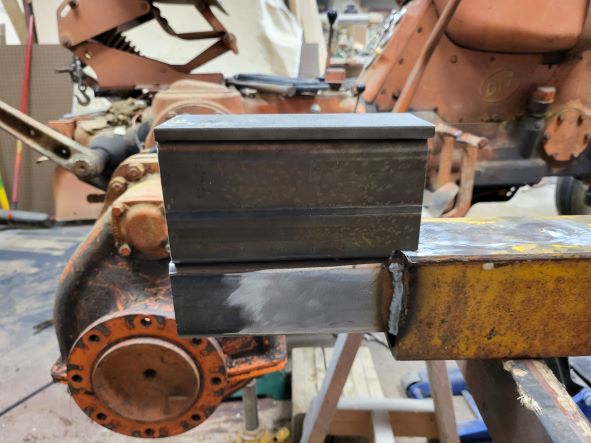 I knew the rear of all of the tubing should be in the same position, and the wall thickness of the outer tubing needed to be cut out of a small part of the 3" x 4" tubing. I also had a piece of 3/8" steel cut to make up the difference in height between the mounting frame and the axle housing. This was a chance to make sure I was able to do math when I did my design work. Last up for the day was to mock up how the entire tubing stack would look and try to figure out how to clamp it all together once I got it under the tractor and ready to tack. 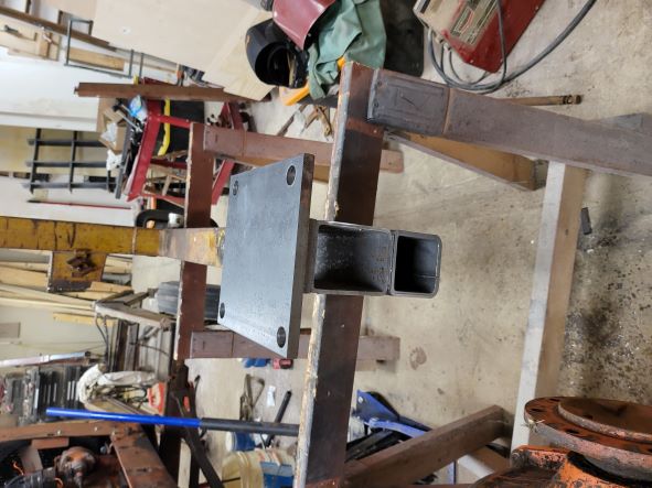 ------------- 1959 AC D17 Gas with some updates |
Posted By: Morpar55
Date Posted: 06 Jun 2022 at 7:32pm
On Saturday the 4th I just basically had a little time to locate the components for under the rear axle and get them welded up. While I got away with it on the right side, when I did the left side I made a few tack welds in addition to the clamps BEFORE I moved things out from under the rear axle. I realized I got lucky and didn't move anything while manhandling this big bunch of steel!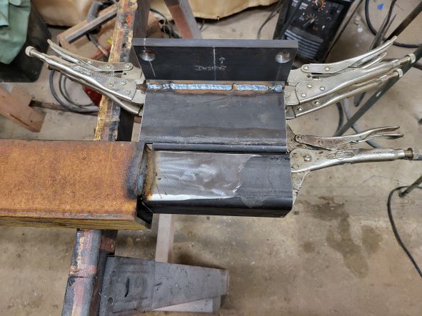 I had gone ahead and welded the 3/8" steel to the top of the 3" x 4" tubing ahead of time, which is why there is a bead of weld there in the picture. After a little bit I had things all welded up and ready to put the end caps on. 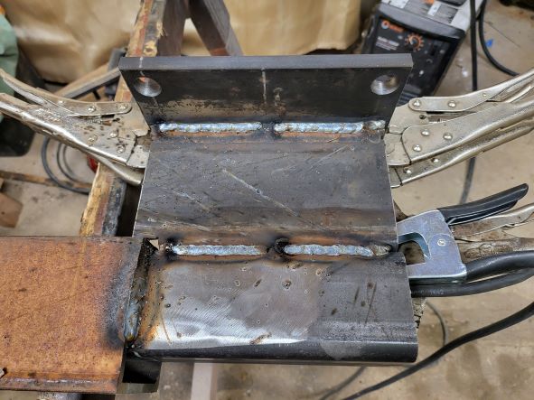 ------------- 1959 AC D17 Gas with some updates |
Posted By: Morpar55
Date Posted: 06 Jun 2022 at 7:45pm
On Sunday the 5th I got another couple of hours to work on this project, but it sure is frustrating only being able to work on it for an hour or two every couple of days! Anyway, I got the end caps added as well as a gusset to the front side. I'm not sure if it needs it, but I figured it can't hurt anything!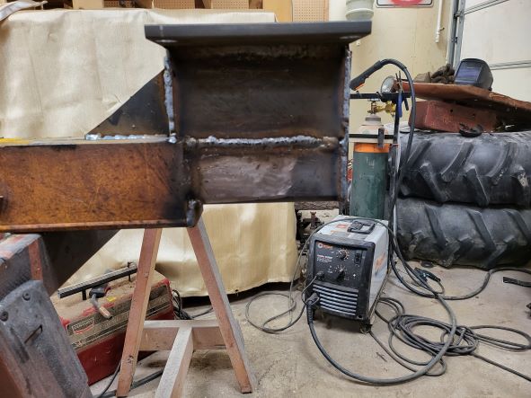 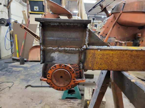 I welded up some of the parts on the front which I had only tacked before, and with that the right side mounting frame is ready to install on the tractor. 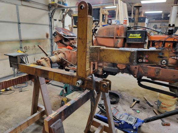 I used new grade 5 bolts and lock washers (since the ones I had been using were showing a little wear) and put anti-seize on all of the fasteners before bolting this on to the tractor. The only thing left is a piece of 1/2" steel I will need as a spacer on the outside edge of the mounting plate. I wanted to wait on it until I had an accurate measurement. ------------- 1959 AC D17 Gas with some updates |
Posted By: Morpar55
Date Posted: 06 Jun 2022 at 8:07pm
I finally got the majority of a day to work on the tractor and feel like I made great progress. I did the same things to the left side axle mount and mounting frame as I did the right side, except I did do a little more tack welding before an oops! 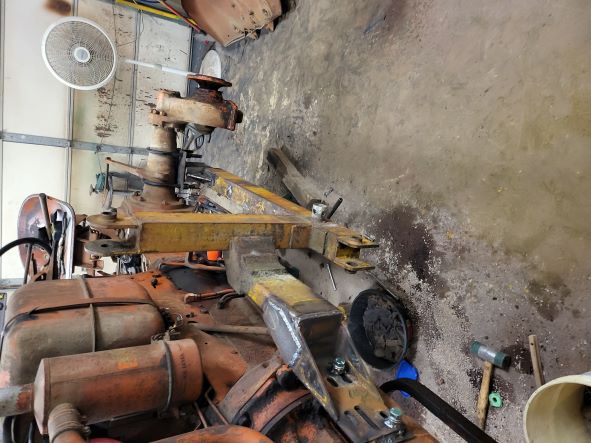 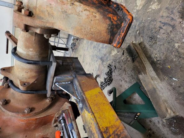 I wanted to get the new headlights fitted once I got the loader frame put back on the tractor. I had to come up with a pair of 1/2"-20 (fine thread) bolts and drill them out to feed the wires into the radiator shell. Then the bolt heads were too thick, so it was back to the lathe to trim them down. In the end the lights mounted the way I thought they would and don't look too bad on this old a tractor. I still need to wire the lights, but I know they will have plenty of clearance for the loader frame. 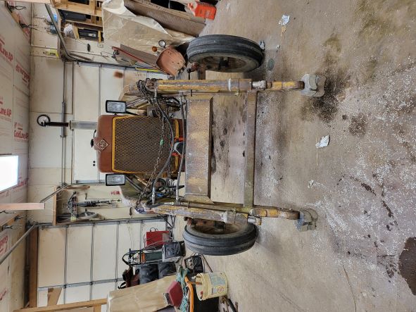 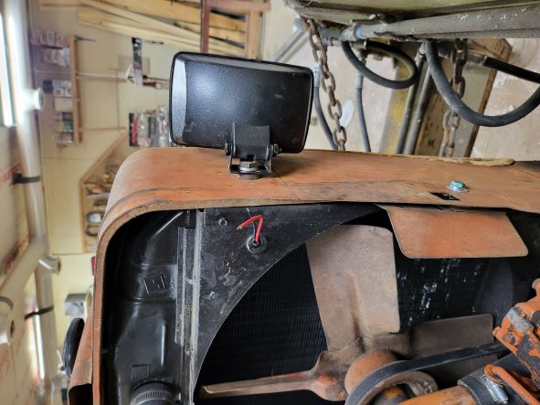 Next up was the mounting bracket for the new hydraulic controls. Before I took the fenders and tires off I decided I wanted to have the control valve on the right side a couple of inches above the fender. I got a piece of 1 1/2" square tubing for a mounting post and secured it to the tractor with one of the 1/2" bolts used for holding the fender to the mounting plate. I also got a short (1 1/2" tall) piece of 2" square tubing to act as a socket on the mounting frame. Now if I need to disassemble something in the future I can! 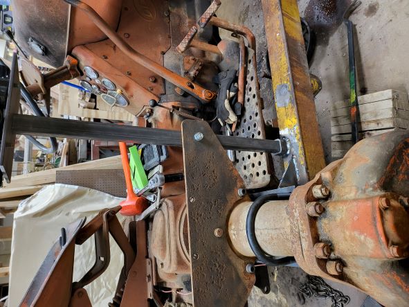 The last thing for today was to fabricate the mounting plate for the control valves. I had to drill and tap 3/8"-16 holes in 3 places on the plate (and I am SO thankful for transfer punches!) and it is ready to weld in place on the 1 1 /2" tubing. I am going to need some help from one of my kids to get the plate in position and well marked, but maybe I can do that tomorrow. If not I still have plenty to keep me busy at this point. And I still need to decide if I think there should be some gussets or not on the underside of this plate. 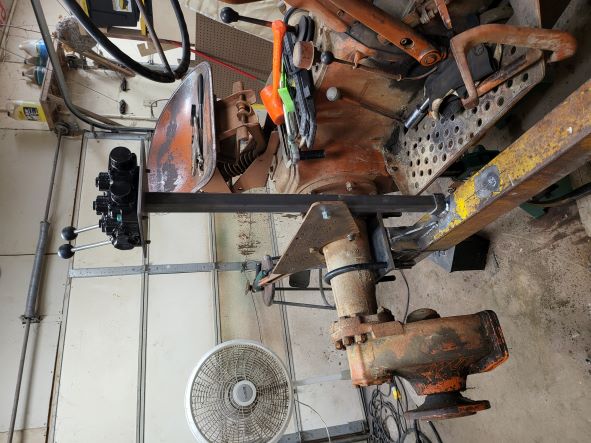 ------------- 1959 AC D17 Gas with some updates |
Posted By: IBWD MIke
Date Posted: 07 Jun 2022 at 7:58am
|
If we had a 'like' button, I'd hit it for this! |
Posted By: EPALLIS
Date Posted: 07 Jun 2022 at 9:52pm
| Always great to see a "D" Series receiving much needed improvements. Thanks for sharing! |
Posted By: Morpar55
Date Posted: 15 Jun 2022 at 2:15pm
I know, I am horrible about keeping things updated on this project! But to be fair I have taken pictures daily, just haven't made the time to pull out the laptop and post them. So when I started back to work on June 8th the first thing I did was put the right fender on temporarily and confirm the control valve location. My younger son also came over and confirmed this is still where we think the valve should go.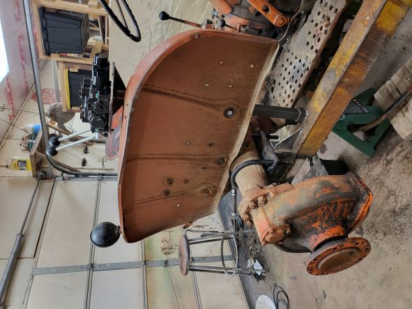 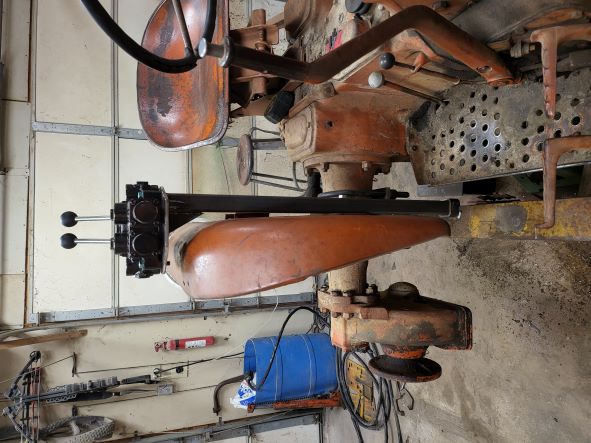 Next up was to add some 1/2" square steel to the outside edge of the "slapper bars" to account for the taper of the axle housing. I gave them a couple of heavy tack welds each and called them good. 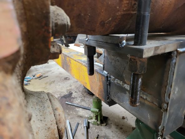 When I took the right fender off the mounting plate holding it to the axle I found LOTS of rust between the pieces of steel. Thye left side was just as bad, so I wire brushed (on the right angle grinder) the pieces to get the rust off and prepped everything for primer. 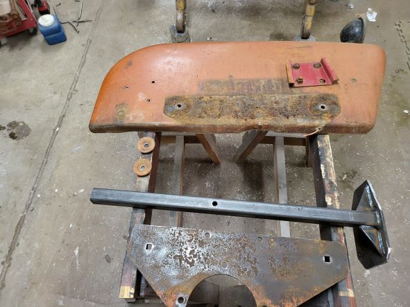 My original plan was to only primer and paint the areas where I had done work or had bare metal, but I did get a little carried away and primed the entirety of the mounting arms too. I just ended up doing the rest of it the next day. 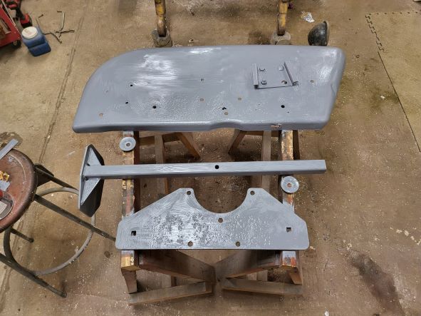 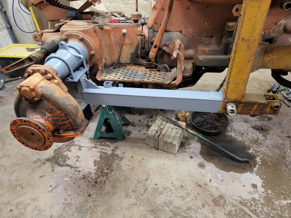 ------------- 1959 AC D17 Gas with some updates |
Posted By: Morpar55
Date Posted: 15 Jun 2022 at 2:24pm
June 9th was basically a day of throwing on some primer, at least as it relates to this project. There was some primer added on the 10th too, as some parts got 2 sides done. I ended up taking off the rear lift arm housing to replace the hydraulic line and replace the leaking O-ring for the cylinder mount. But I digress. Before I separated the left fender from it's mounting plate I took a couple of pictures so I would know where things get bolted back together for reassembly. And no, I am not responsible for the crumpled fender and neither was my Dad. I don't want to get into doing a restoration right now, so all I did was clean it up a bit, knock out a couple of dents, and BRUSH on the primer.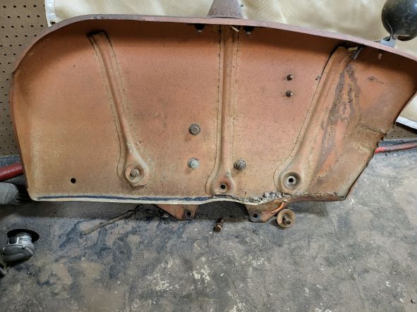 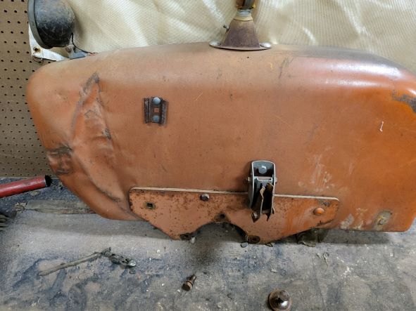 I went ahead and primed the rest of the mounting arms too while I had the brush out and was making a mess! 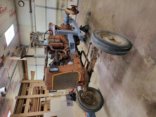 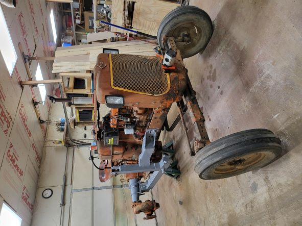 ------------- 1959 AC D17 Gas with some updates |
Posted By: Morpar55
Date Posted: 15 Jun 2022 at 2:30pm
June 13th and 14th were painting days in addition to some other buttoning up things from the rewiring project last fall. I also replaced the fluids in the Power Director, hydraulic system, and of course the transmission. But I sure am tempted to paint the whole tractor now after seeing the new orange paint applied!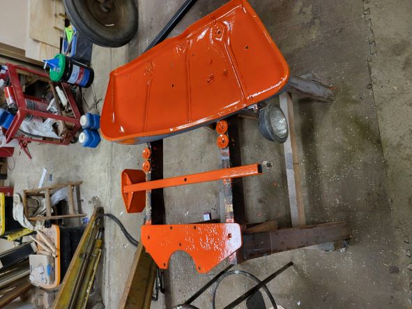 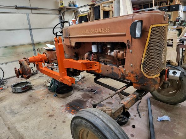 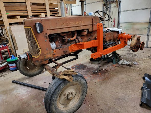 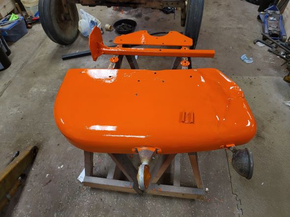 I also put down some skid tape on both of the mounting arms. The tops of these arms are about 25" off the floor, so at some point I need to add some sort of step. The original mounting arms dropped down and made the step up to the footboards pretty easy. 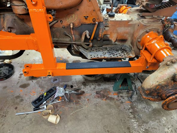 ------------- 1959 AC D17 Gas with some updates |
Posted By: Morpar55
Date Posted: 15 Jun 2022 at 2:51pm
|
Today was a big assembly day, as I need to be able to get the tractor out of the shop for a woodworking project I need to deliver and install on Sunday. As of right now there are a few big items left to do to finish this project up: 1. Design and fabricate a hydraulic reservoir. 2. Mount the hydraulic filter. 3. Replace the hydraulic lines going down the lift arm. They are currently on both sides of the lift arm which will make the new lines longer than really needed. There is a place in the next town over that makes hard hydraulic lines as well as flexible lines, and they would prefer I just trailer the tractor over and give them a couple of hours to make and install everything. 4. Run the control lines from the pump and reservoir to the control valves and filter. I want to do this at the same time as the other lines. 5. Design and fabricate a guard for the front pump and lines. So on to the pretty pictures! 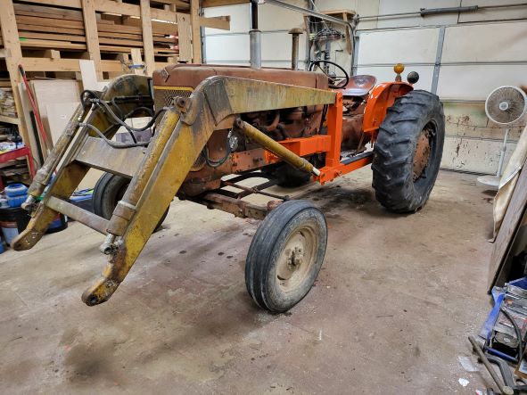 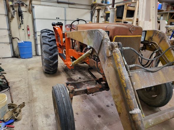 I took the pump off the front as I was afraid to run the engine with it still in place and not getting any lubricant. It's 2 bolts, so why take any stupid chances? Taking the pump off reminded me of a modification I had to make in the front pump mount kit I bought. Originally there were a pair of hex-head bolts holding the mounting plate and spacers to the front casting. With the pump I ended up using these bolt head wouldn't allow the pump to mount. I had the holes countersunk at work and purchased flat head bolts to clear. I also knocked out the hole through the grille to let the pump drive shaft go through. 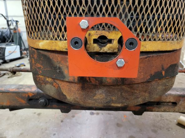 I had to shorten the pump drive shaft earlier, so here is a shot of it. 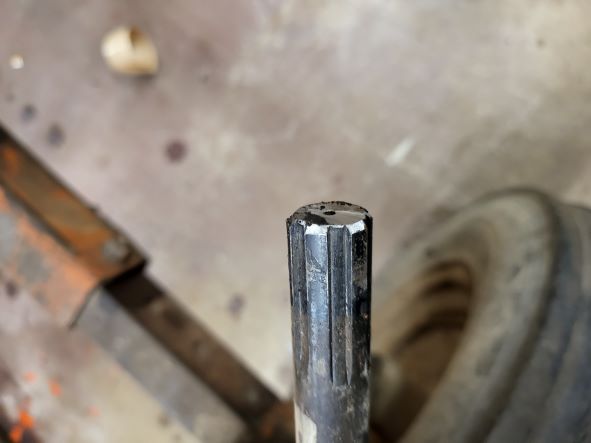 And last is a top view of the control valve on the stand. I purchased the valve from Northern tools and got it on sale. 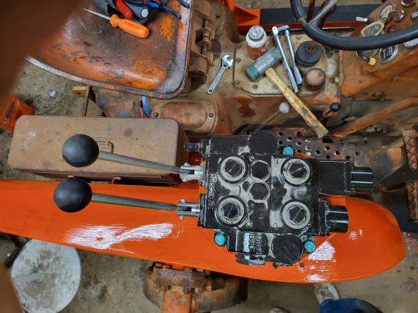 The pump I got from Surplus Center. I don't have all of the specs handy, but if my memory serves it will flow 15 GPM at 2000 RPM and supply up to 2500 PSI. 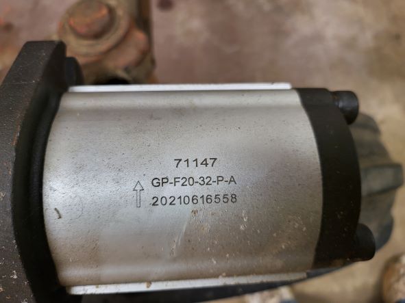 Hopefully next week I can get moving on the last few items and get this whole project operational. ------------- 1959 AC D17 Gas with some updates |
Posted By: DrAllis
Date Posted: 15 Jun 2022 at 3:33pm
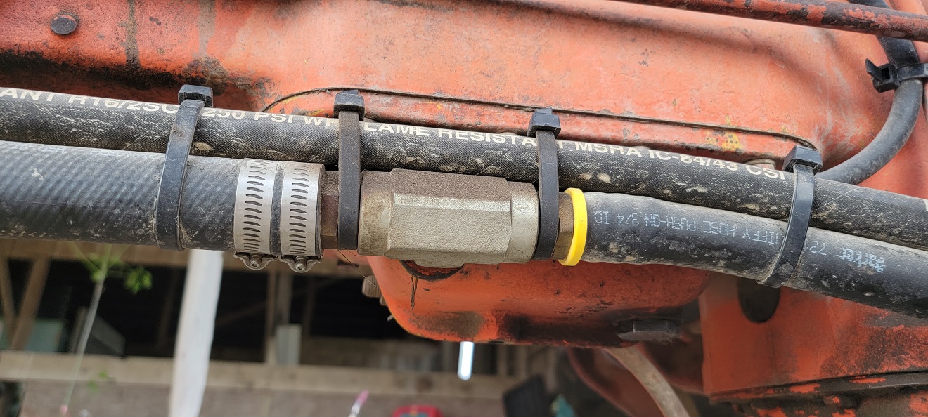
| You don't need to design and fabricate a hydraulic reservoir. Use the tractors existing hydraulic sump. Drill/tap a hole in the left front side corner for 3/4" pipe thread. Install a short 3/4" nipple and then a 3/4" tee. Position tee sideways and run forward to the pump with suction hose. Return oil goes thru a filter after the valve stack. Oil from filter shoots into the rear of the tee flowing right back to the pump suction hose. |
Posted By: jeickman01
Date Posted: 15 Jun 2022 at 5:42pm
| This is probably the one comment I have been looking for a long time. Was almost ready to fab a reservoir for a Series III. However, I'm afraid of drilling a hole into the torque housing that I may never be able seal if it doesn't work out right. Pictures from someone who's done this or more port location info from Dr Allis? |
Posted By: DrAllis
Date Posted: 15 Jun 2022 at 6:01pm
| Not drilling the torque housing. Drilling and tapping a hole in the cast iron sump bolted to the bottom of the torque housing. I can e-mail you a picture of the location. All D-19's have a threaded hole connection in the same exact spot. |
Posted By: tractorboy
Date Posted: 16 Jun 2022 at 3:27pm
| Nice work ! All my stuff is mostly cobbled ! keith so. va. |
Posted By: coggonobrien
Date Posted: 17 Jun 2022 at 9:32am
|
Posted By: DrAllis
Date Posted: 17 Jun 2022 at 10:14am
| The first one I did (45 yrs ago) I just drilled and rethreaded the drain plug hole. Worked fine, but stuck down much lower and was in harms way much more than this method. Either way, the sump must be taken down to do the modification. When you see all the dirt and crap inside the sump, from A-C not having a real filtering system, you'll be glad you did, so you can clean it out good and clean the screen that's there too. |
Posted By: Morpar55
Date Posted: 22 Jun 2022 at 6:32pm
So after some much needed shop clean up the tractor made it back into the shop today. I had to take it out and put it in the barn last week to get a woodworking project out over the weekend for a paying customer. Yesterday before it got too hot I took a trip to the "local" tractor salvage yard looking for steps to add. The new loader frame sits a lot higher off the ground than the original and with my knees the way they are right now getting to the seat just plain hurts! Plus all of my kids are shorter than I an so it will help them in the long run too. The top of the loader frame is 24 1/2" off the shop floor, so I wanted to come up with something to split the difference. When I went searching the cannibalized AC tractors I found nothing. But when I was walking past the John Deere stuff there were TONS of a little step which would be pretty easy to add and get what I want. I ended up picking up a pair of these and making them do what I wanted fairly easily. I stopped and got a couple of pieces of 2" angle with a 3/16" thickness since that is what Tractor Supply had. I cut off 1 foot long pieces (4 total) and then drilled holes for both the steps and to mount them on the tractor. A couple of 1/2" bolts and I was ready to try them on the tractor.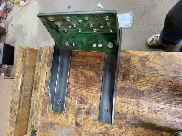 I spent a fair amount of time getting these located on the loader frame before I drilled and tapped a pair of 1/2"-13 holes on each side of the loader frame. Vise Grips and spacer blocks (in case the Vise Grips let go when I was standing on the step) helped me get the right location. I found out the hard way I wanted to angle the outside edge of the angle iron, as I caught the bottom of my pants getting down one time. No tumble to the floor, but a good reality check. 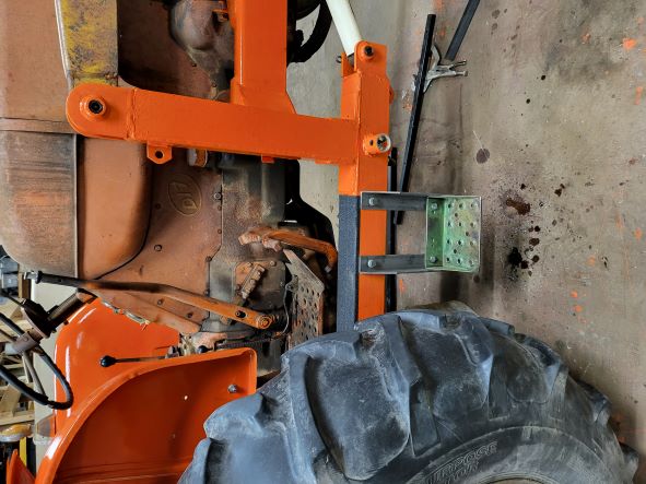 Lastly (and maybe most important) I took the steps back off the tractor and shot them with a coat of primer. Not because they were green (although that was a factor), but because I had bare metal. Tomorrow morning the AC orange will get brushed on one side and Friday on the other. Saturday should see the steps getting installed and ready for use. 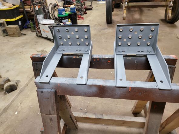 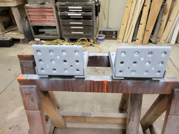 Next up is the hydraulic reservoir. I have given a LOT of thought to modifying the factory hydraulic housing as Dr. Allis suggested, but the engineer in me says to build a reservoir and keep the systems completely separated. Plus I had already purchased all of the parts (steel, filler neck, sight glass for fluid level, strainer for going to the pump, and miscellaneous weld-on fittings to go into the tank) and it seems a shame to waste them. I should be in the 8 gallon range of tank capacity (including a 10% head space) when I'm all done. I plan to make a cardboard mock-up to see if it fits tomorrow before I start cutting and welding steel. Plus I need to contact the shop which will be bending all of the new hardlines to determine what my bend radius for each size of tubing will be and figure out if they have all of the fittings I will need or if I need to order them from somewhere.
------------- 1959 AC D17 Gas with some updates |
Posted By: BillinAlberta
Date Posted: 24 Jun 2022 at 11:59am
|
Fine workmanship! I am wondering though how you kept your white shoes so clean?
|
Posted By: Morpar55
Date Posted: 29 Jun 2022 at 7:23am
You caught me! I had my photo-taking shoes on. Here's the normal work-in-the-shop shoes. Liberal application of orange paint, dirt, grease, epoxy, and I think there is a little wood stain on them too! ------------- 1959 AC D17 Gas with some updates |
Posted By: Morpar55
Date Posted: 29 Jun 2022 at 7:42am
As usual I didn't find time to post anything, so here are a couple of days of catch-up. On Friday June 24th I started off by painting the new steps.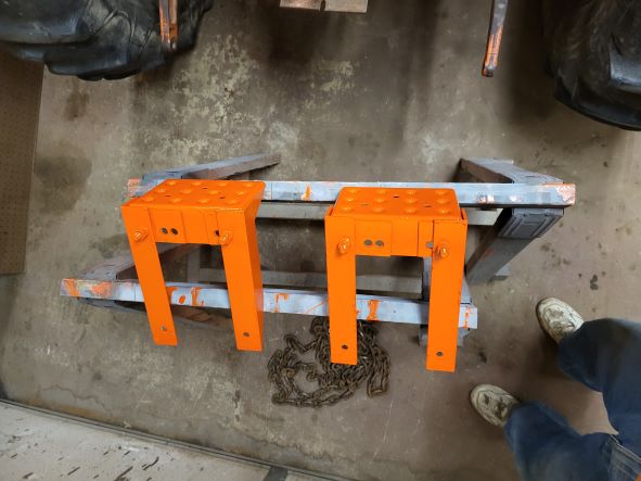 Once I had the steps painted and out of the way it was time to start on the hydraulic reservoir. I had spent some time making a cardboard template to check clearances (including front axle articulation) to determine the final size and shape of the reservoir. Thanks to my youngest son I had a box from a 55" TV which was great. All heavy corrugated cardboard, great for making templates and prototypes, almost makes me want to go buy a new TV just for the box! Anyway, the final design will hold around 7 gallons of oil with a good head space. I made my cut list and started in with the angle iron and flat plate. I started making the bottom and working my way up. 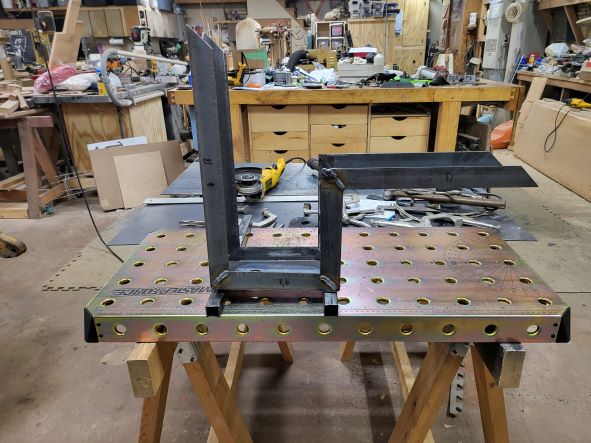 The bottom has a weld-on bung for using a 3/4" pipe magnetic drain plug. 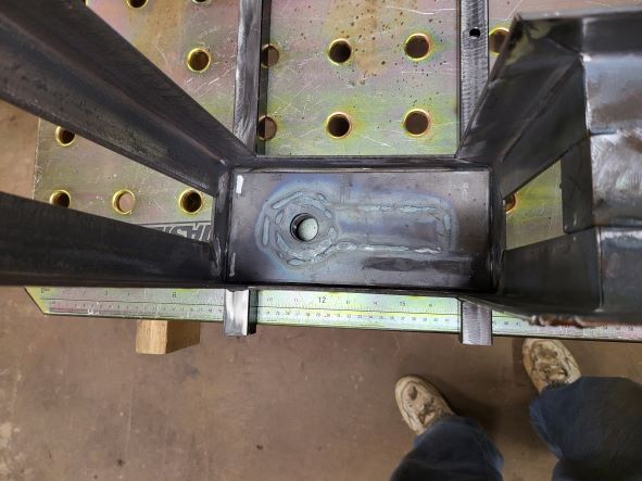 Since I don't have a metal brake I am building this using angle iron for the exoskeleton with plate on the inside, except for the top. This way I can run a weld bead on both the inside and outside to prevent leaks. At least that's my plan, we'll see how it goes! 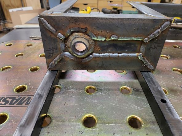 ------------- 1959 AC D17 Gas with some updates |
Posted By: Morpar55
Date Posted: 29 Jun 2022 at 8:08am
Monday the 27th dawned with me having almost nothing on my calendar for the day, so lots of progress was made. All 3 ends and the back were added, as well as the suction port and the inlet port. I also discovered a slight problem which was solved with a clamp or 2. I got the remaining pieces of angle welded onto the framework and then made the end with the inlet. Just like on the bottom I had to notch out the angle due to the narrow design of this reservoir.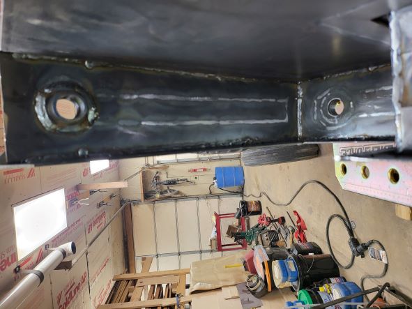 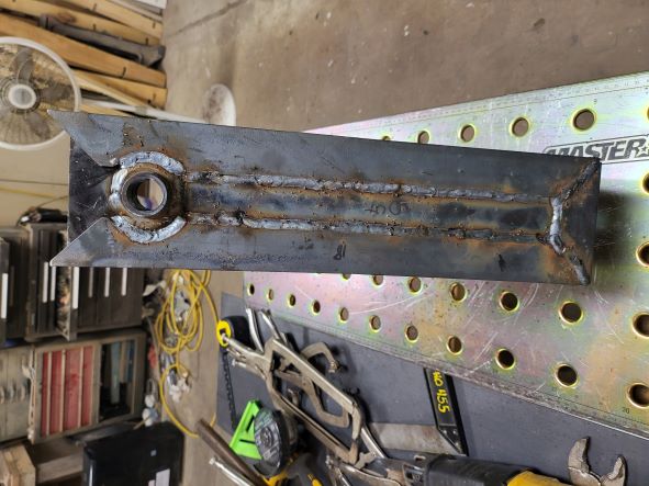 Next I did the small end where the suction port goes. The strainer I purchased uses a 2" pipe thread to screw in so I used a larger weld-in fitting than before. It had enough of a lip on the inside I welded it inside too. 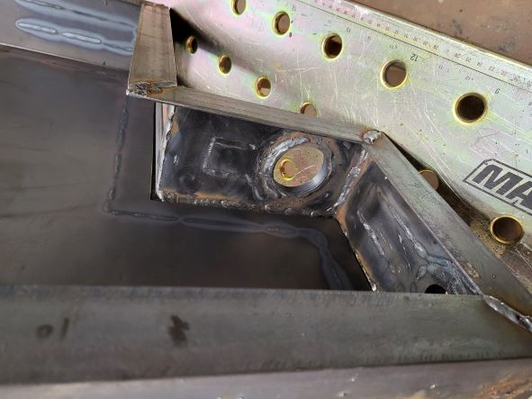 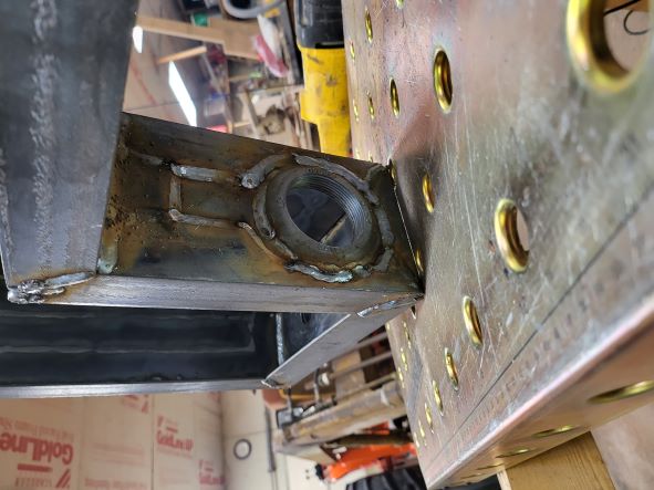 I had made a trip last week to the business which is going to bend all of my new lines and make the hoses to get the bend radius on the various sizes of tubing and to make sure if we needed to order fittings they would have time to arrive. This helped a bunch during design to know what clearances would be needed for the lines to reach AND stay out of the way. Once the last difficult end was done I added the last end and then the back side. This is where the clamps came into play. I "knew" what size this tank is supposed to be, but when I started measuring to confirm for the back side I was about 5/8" longer than it should be. I had already welded up the frame for the top and found I could use a pair of pipe clamps to get things back the way they should be. Mostly. I wasn't real happy about the way the top framework fit, but figured some more clamps later on would take care if it. Anyway, a couple of pipe clamps and some cutting, fitting, and welding and the back was in place. 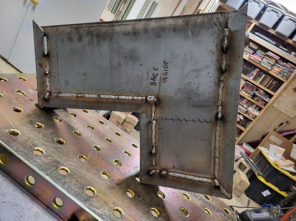 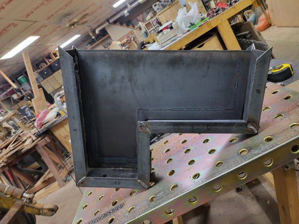 ------------- 1959 AC D17 Gas with some updates |
Posted By: Morpar55
Date Posted: 29 Jun 2022 at 8:53am
Tuesday morning my plan was to get the reservoir all buttoned up and ready for leak testing. Well, I got more work done, but not to that point. Since all but the front side panel was installed it was time to go to work on the interior. First the floor was added. I cut a piece of steel to fit along the entire interior and then notched it out to act as a baffle and slow down the oil flow. Once the floor was in I added the incoming line and plumbed it, since there will be no way to do it once the tank is finished. I used a 3/4" galvanized street L and 10" nipple to make the inlet. Once it was all put together next was adding the upright baffle. I left it 2" short of the front of the tank and I also had to notch it to clear the filler screen and the incoming pipe I had just added.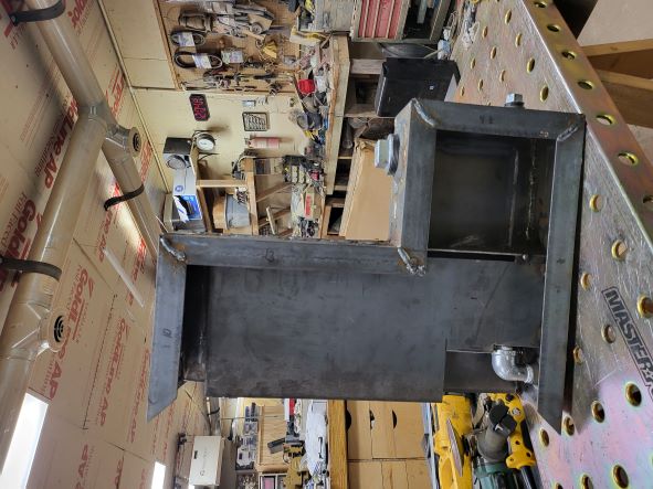 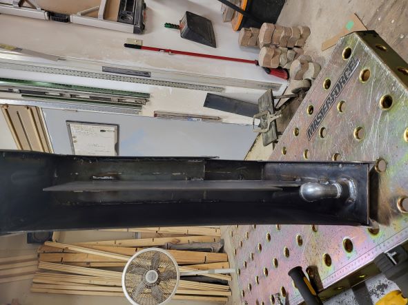 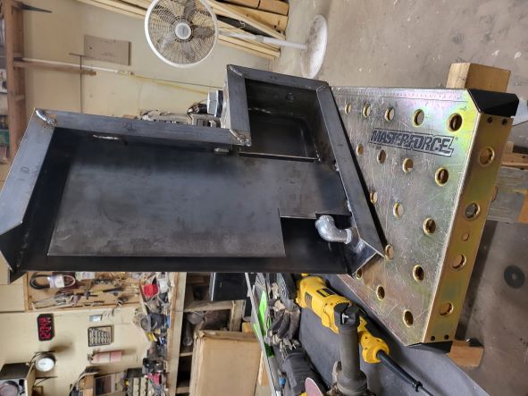 At this point I wanted to add my mounting points while I still have some access to the interior. I rigged up where I wanted the tank to go and started looking for decent places to anchor it. I left 1" of clearance between the tank and the frame to allow the pressure line from the pump to be run out of harm's way. 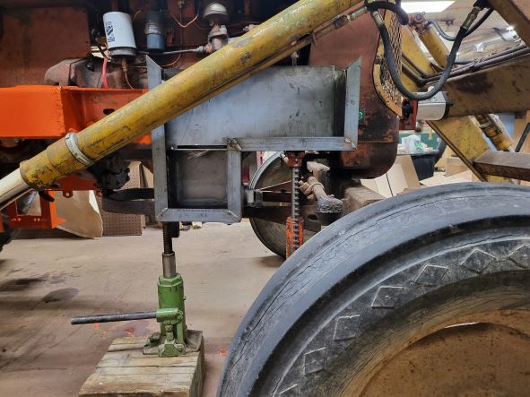 To be honest I got really lucky on my mounting points! There was a 5/8" tapped hole at each end which worked out perfectly with some 2" angle iron. The back side hole is one of the mounting bolts for the loader frame, and the other will be part of the protection for the pump (still to be made). 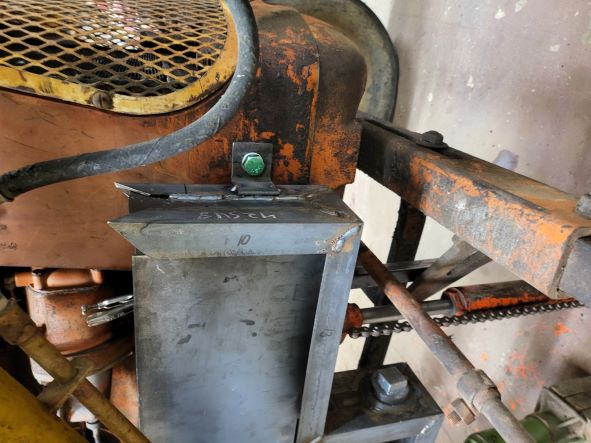 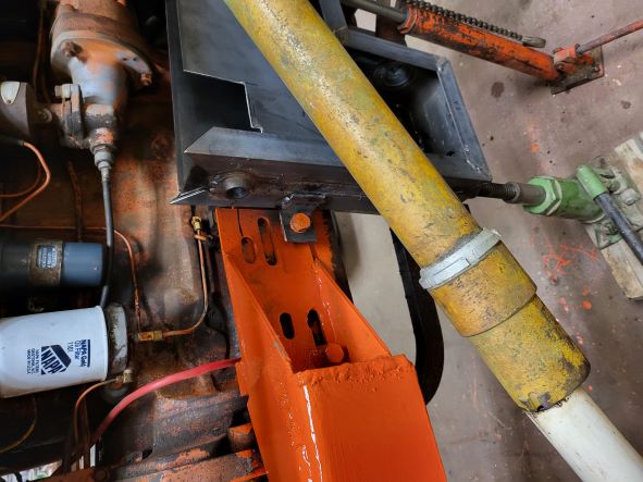 Once the hydraulic lines are run I plan to add some 1" square tubing between the frame and tank to help support the tank more and keep it from flexing. At this point I took the tank off, welded up the brackets, and went to work on the top. I had already cut and welded up the top framework, so I cut a piece of steel for the top and welded it on (strange, the angle iron seems to be wider at one end than the other) then went to the drill press and used a hole saw for the filler hole. After confirming the screen will fit I laid out the holes for the mounting bolts and drilled and tapped them. Great! Fantastic! 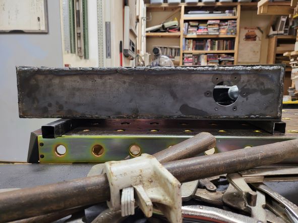 So let's fit the top onto the rest of the tank and figure out where to make clearance for the sight glass and measure for the final side panel. Now, I knew on the front side it would need a clamp to account for the bowing I discovered before. No problem! We're getting some work done today! Once I had used 4 clamps and 2 hammers I had this: 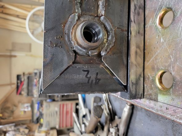 Kind of a large gap, but workable. This doesn't have to be pretty. Oh, then there's the other end... 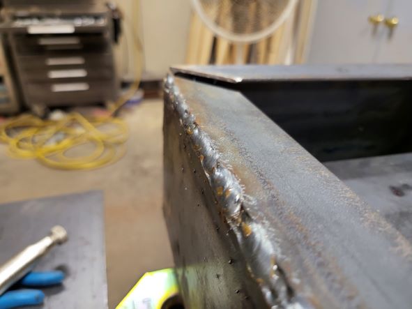 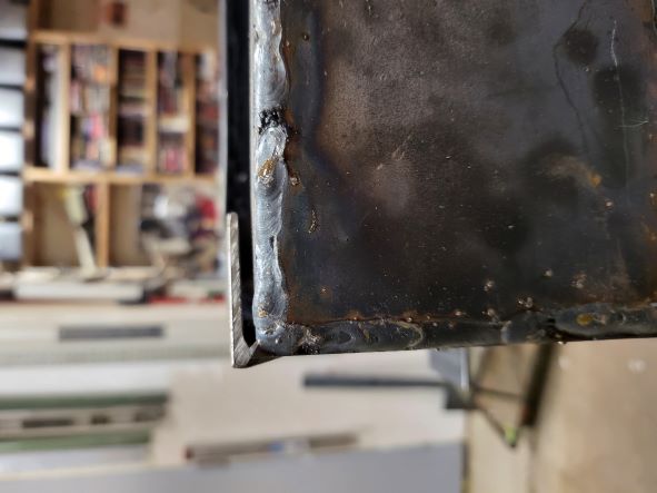 OUCH!! Well now what to do??? Curse words flowing like water!! Well, I may as well put the steps on and then go shower and have a couple of cold adult beverages! 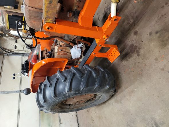 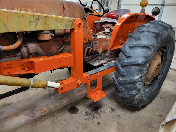 Follow up; after a couple of adult beverages and some conversation I decided I will go ahead and get the front side clamped and on size, install the front panel, then remake the top. At this point I will be out a little bit of steel, but I think I will spend more time trying to fix it than to just make a new one. ------------- 1959 AC D17 Gas with some updates |
Posted By: Morpar55
Date Posted: 26 Aug 2022 at 6:37pm
So it has been a while since I updated this project page. I got busy with other things, I had a company do a crappy job making and installing hard hydraulic lines, we lost internet for a month, and I screwed up having a pump guard made! But progress has been made, so here we go trying to play catch up. So I forgot to take any pictures of the new top for the hydraulic reservoir, in fact I forgot to take pictures at all until it was all welded together!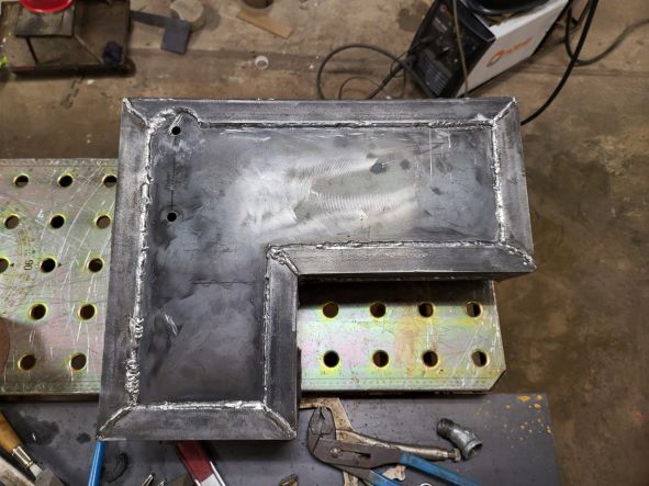 I had to notch out the top to clear the sight glass/temperature gauge. 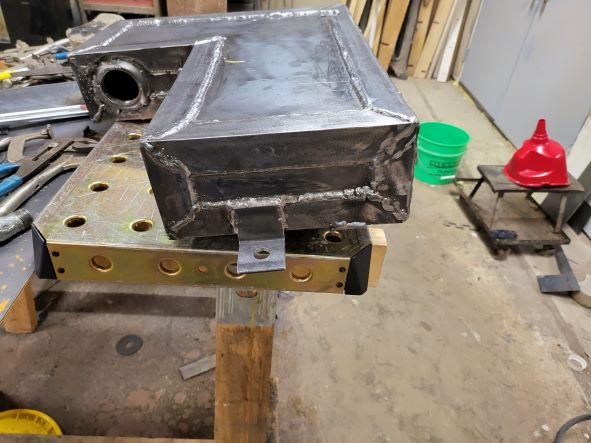 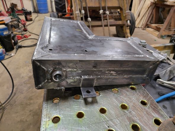 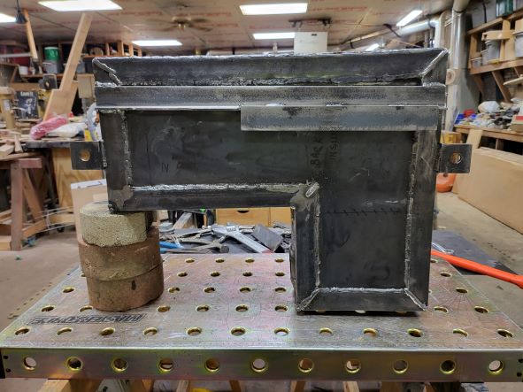 I added some angle to the back to hang over the frame. This should reduce the potential twisting on the mounting tabs and make it easier to install the reservoir. Once all of the lines are run I will add a couple of pieces of 1" square tubing to contact the lower part of the frame to eliminate the chances of twisting. Next up was primer and then paint. Suffice to say I missed pics with paint, but I did get primer! 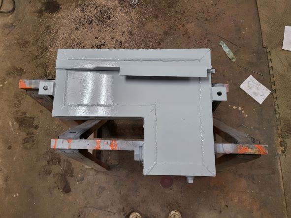  After I had everything primed I did a full water test and found there was some seepage. I ended up getting a gas tank sealer kit and used it following the directions. It ended up taking 4 days to install. The first day was to clean the inside of the tank, second day was to use an acid etch, third day was to let it get good and dry from rinsing out the etch, and the forth was to apply the sealer. Since I have yet to add oil to the reservoir I can't confirm it is sealer, but one of the guys I used to work with builds custom motorcycles on the side and he swears by this stuff! Once the sealing was all done I painted the reservoir orange and installed the suction side strainer, sight glass, and filler cap. After another day I installed the reservoir and was ready to go to get the hard lines made and installed. ------------- 1959 AC D17 Gas with some updates |
Posted By: Morpar55
Date Posted: 26 Aug 2022 at 6:55pm
|
The hydraulic line install was a huge pain. I had to trailer the tractor about 20 miles away after I went and rented a trailer. It was bleeding hot, my truck no longer has A/C, the transmission was acting up, and the morning traffic was stupid but we got there. To make a long story short even though I had taken pictures of what I wanted done and conversing with the owners about this whole project they backed out less than half way through! I did manage to get them to at least finish the pressure line from the pump to the valve pack, but they did a crappy job of running the portion up by the axle. They did recommend another company to finish the job, and they actually do this kind of work! The only problem is I have had to wait about a month to get in. I went and talked to the owner (showed him pictures too) and he assured me they do what I want regularly. In fact he had another D17 sitting outside they were doing similar work on, so I feel I will be in good hands. After I got the tractor home I started working on a pump guard. I know how I am, and if I don't put something up there now I will have after I break the current pump! Unfortunately I was an idiot and made a cardboard template with the bad plumbing in place. Then I measured the angles and length and made a drawing to send to a local shop to bend out of 3/8" think steel. When I got the guard I about came unglued. There was no way it would even come close to fitting! I checked the part against my drawing and lo and behold they matched! All my fault on this one, and another lesson re-learned. So I grabbed some 3/8" plywood, took off the hard lines, dug out some hinges and made an extremely ugly template. 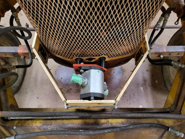 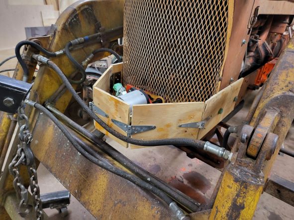 All told I spent maybe an hour making this template and a better drawing to go with it. It took almost a week to get this made (I had them drill the mounting holes and took them the template) but I got exactly what I wanted. 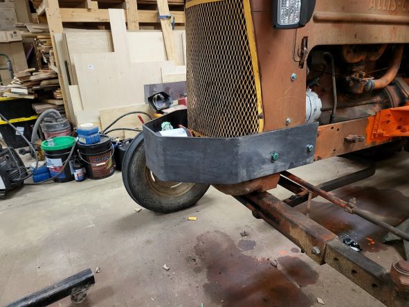 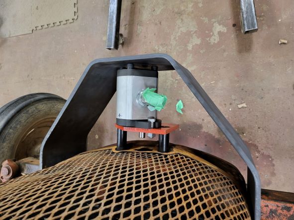 The work was done by Advanced Repair and Machining in Lafayette, Indiana. They also sell steel in the smaller quantities I need. Very good people to do business with! I checked all of my clearances with the loader, marked where I need a notch on the right side, and took the guard off for cleaning, primer, and paint. Hopefully I will have this all installed tomorrow and ready to go when I get the call to bring the tractor up for the rest of the hydraulic lines. ------------- 1959 AC D17 Gas with some updates |