1950 B Hydraulic Cylinders Questions
Printed From: Unofficial Allis
Category: Allis Chalmers
Forum Name: Farm Equipment
Forum Description: everything about Allis-Chalmers farm equipment
URL: https://www.allischalmers.com/forum/forum_posts.asp?TID=171679
Printed Date: 23 Mar 2026 at 1:20pm
Software Version: Web Wiz Forums 11.10 - http://www.webwizforums.com
Topic: 1950 B Hydraulic Cylinders Questions
Posted By: SC_MudDuck
Subject: 1950 B Hydraulic Cylinders Questions
Date Posted: 01 Jun 2020 at 10:13am
|
Hello again friends. Took the weekend to work on getting the B up to snuff to run a bush hog (SQ600). As I said in a different post, I have a hydraulic leak directly from the cylinder that needs to be repaired. Started my research, but cannot figure out which cylinders I have as I cannot find a matching 3pt hitch to reference to start comparing. All the 3pt hitch I have been seeing for sale or on Google Images use 1 cylinder. My setup has 2 under the seat. Do I need both? Is one a drive and the other a slave? What I have been seeing for sale is a 2" x 8" stroke, is that enough? Trying to make a decision to either repack the current cylinders or buy new. Has anyone else seen this on a B and can make some recommendations? If more information is needed, please let me know and I will get whatever I can. I look forward to again learning from this massive knowledge base!
|
Replies:
Posted By: Larry in NC
Date Posted: 01 Jun 2020 at 10:29am
| If you have two mounted cylinders, those are most likely original that were installed to operate two way plows. If this is the case, your tractor has a two position hydraulic control valve. You move the control lever to the right to operate one cylinder and to the left to operate the other. The after market three point hitches normally use one larger cylinder. You do not want two larger volume cylinders because the lift will be very slow. The B has a high pressure, low volume pump. |
Posted By: SC_MudDuck
Date Posted: 01 Jun 2020 at 10:37am
|
Hmmm... That's pretty cool! I didn't know anything about the left to right action, I only used forward (down) and back (up). I'll have to give this a try when I get home. Do you happen to know what the bore size would be or a part number?
|
Posted By: steve(ill)
Date Posted: 01 Jun 2020 at 1:45pm
|
the factory B cylinders are something like 1 inch size.. If it leaks at the packing nut on front, just try to tighten it with a pipe wrench another turn... That cylinder runs at 3200 psi so that is a LOT OF LIFT .... The larger 2 inch cylinders are normally rated for 2000 or 2500 psi... You can damage one or blow the packing if you run the higher pressure constantly... AS mentioned, the BIG cylinder takes a lot more oil to fill and will go a lot slower to lift.......... I actually used a cylinder off a CA when i converted by B... i think it is 1.5 inch.. Old WD cylinders are nice also, but kind of long to fit in the space. ------------- Like them all, but love the "B"s. |
Posted By: SC_MudDuck
Date Posted: 03 Jun 2020 at 11:35am
So, there is no left to right on my setup. There is 1 lever on the right hand seat that only moves up and down. How does this affect my setup? I have on hose going from the cylinder into the control from the same orientation as the cylinder and the other cylinder is attached to the top of the control valve going to the other cylinder. Should my control valve be setup differently? I also wish there was a way to set the lift so that it stays put.
|
 Larry in NC wrote:
Posted By: SC_MudDuck
Date Posted: 03 Jun 2020 at 11:37am
Its pretty tough to tell exactly where the cylinder is leaking at this moment. I will try to take some degreaser and pressure washer to it this weekend to do some looking around.
|
Posted By: SC_MudDuck
Date Posted: 03 Jun 2020 at 11:54am
|
This is what I see when I look at my hydraulic control lever. https://imgur.com/aeQNil8" rel="nofollow - https://imgur.com/aeQNil8
|
Posted By: Larry in NC
Date Posted: 03 Jun 2020 at 11:59am
Yours is single action so the rams would have to work together if they are both hooked up. There would have to be a tee to connect them. Here are are pictures of the dual control. 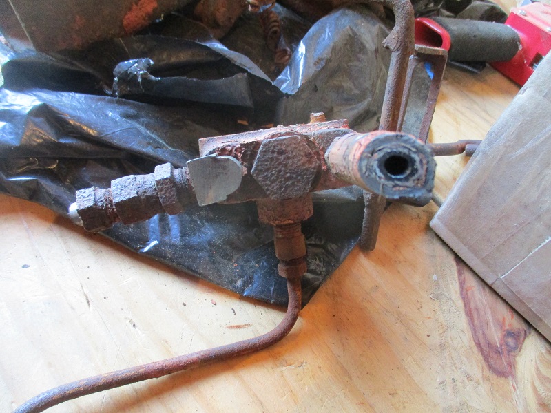 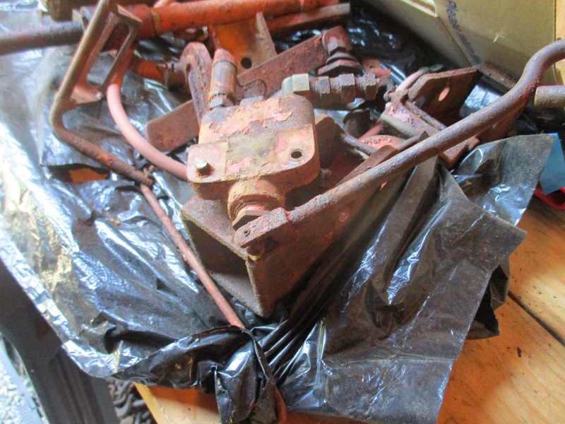 |
Posted By: Bill Long
Date Posted: 03 Jun 2020 at 12:22pm
|
What is described above and shown is a control that directs the oil flow to either one or if the control is in the middle to both. As stated that is used for a two way plow whereby you lift one or the other. If you do not have that then check the plumbing to see exactly where the hoses from the rams connect. Also, when you call for lift do both rams expand. If you could post pictures of your system showing the rams and the plumbing so we can see how they are connected. Take good care of my favorite. Good Luck! Bill Long
|
Posted By: SC_MudDuck
Date Posted: 03 Jun 2020 at 7:05pm
|
A few photos for my friends. Below is a few photos from multiple different angles. Hopefully you guys and gals can make it out under all that caked on mess. Took a stab at degreasing the area after the photos to no resolve. What works best to cut the grease away?  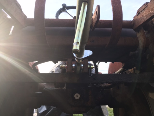 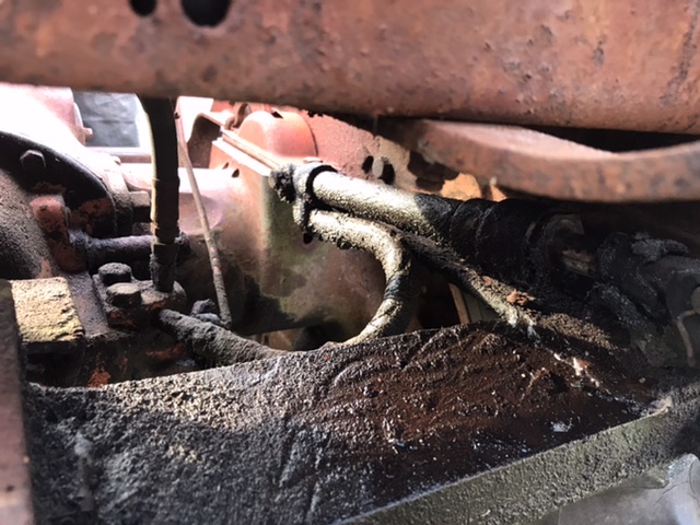 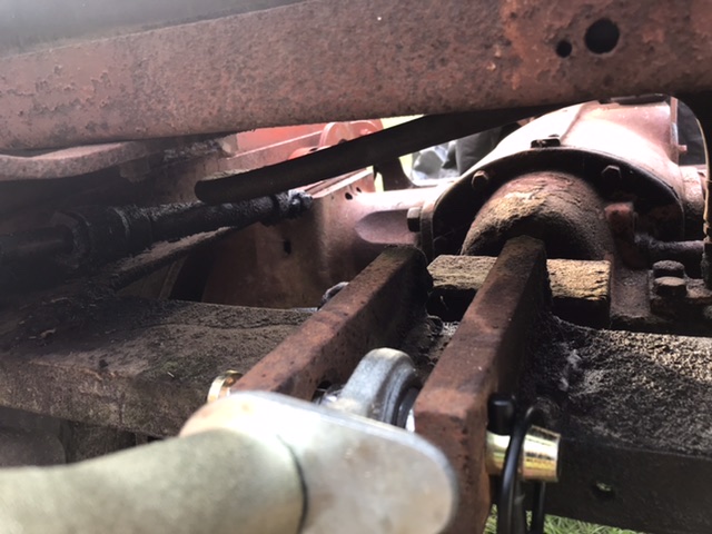 
|
Posted By: SC_MudDuck
Date Posted: 03 Jun 2020 at 7:08pm
A few more for clarity.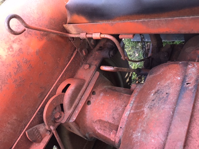 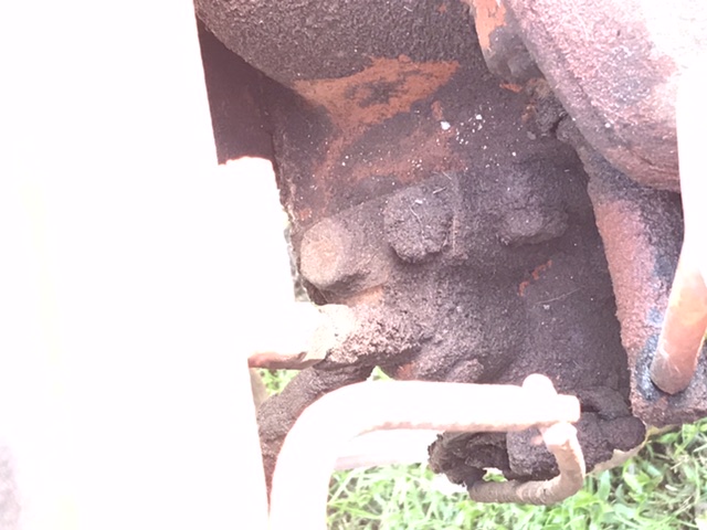 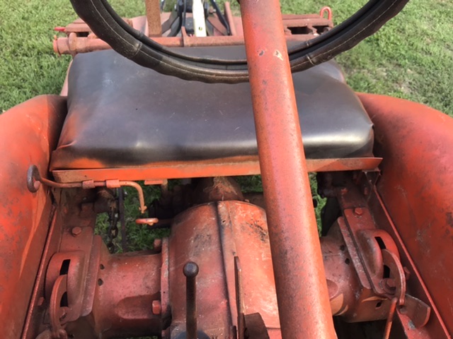
|
Posted By: steve(ill)
Date Posted: 03 Jun 2020 at 7:20pm
|
You have the standard B hyd pump with the standard single control handle.. Normally for two cylinders you would TEE them together and connect to port 8 coming out the BACK of the valve.. The port 6 on top is to measure the pressure output, but i guess its OK to connect the second hose to it... SEE BELOW.... Yes, everything is VERY DIRTY.. Dont blame the cylinder right off, it could be an old leaking hose or fitting... Pressure wash first, then look............ If your pump/valve is working correctly it should have a HOLD position when you let go of the lever.. If it is just dropping when you let go, then the round cam / spring on the side of the valve is STUCK or the spool inside the pump is STUCK.  ------------- Like them all, but love the "B"s. |
Posted By: SC_MudDuck
Date Posted: 03 Jun 2020 at 7:30pm
| Awesome! I’ll give’r a good washing and top her off afterwards and see what we have going on. Maybe tomorrow after work...not very patient, can’t wait for the weekend! THANKS!!! |
Posted By: steve(ill)
Date Posted: 03 Jun 2020 at 7:36pm
|
You also have two standard B hydraulic cylinders. Nothing special.. Looks like someone has added a TOP LINK to make a 3 pt system.. I cant see the lower arms or how it is working. Normally the "B" cylinders will operate the rock shaft and arms that are mounted to the back of the seat frame.... i guess you have a couple LOWER ARMS that were added ? Now i can see the round cam and spring area on your valve / pump... They are buried in CRUD.. that might keep it from working correctly... A good pressure was is in order... If you dont have that, a couple coatings for oven cleaner might work.......... I prefer to chip off everything ( crud) i can with a putty knife, then wash with gasoline and a brush to get deeper. ------------- Like them all, but love the "B"s. |
Posted By: steve(ill)
Date Posted: 03 Jun 2020 at 8:03pm
Ii dont have a real good photo of a B pump/ valve .... This is an IB so the seat is removed and the final drive housing is rotated... but look at the valve... Normally the HOSE comes out the BACK at a 45 degree angle... and to the side you can see the CAM and SPRING... that has to be FREE and operational if you want the system to HOLD when you let go of the control handle. ------------- Like them all, but love the "B"s. |
Posted By: SC_MudDuck
Date Posted: 03 Jun 2020 at 8:50pm
Thanks Steve, I am picking up what you’re throwing down with that illustration! I will try to take a photo of the lower before leaving for work. You helped me solve the problem of why my hitch didn’t look like any of the others I have seen on images. Crafty solution.  You gotta do what makes sense I reckon! You gotta do what makes sense I reckon!
|
Posted By: SC_MudDuck
Date Posted: 04 Jun 2020 at 9:03am
|
I have attached a few photos of the lower lift arms to complete my setup. 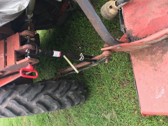  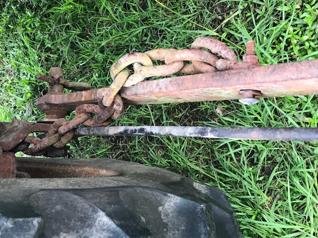 |
Posted By: SC_MudDuck
Date Posted: 04 Jun 2020 at 6:47pm
After the initial pressure wash.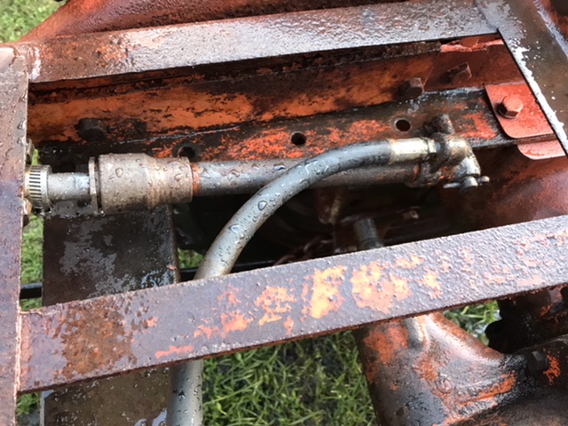 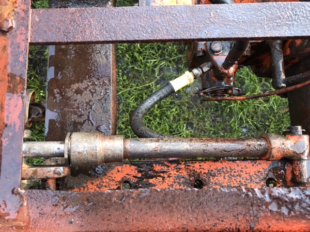 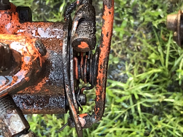 I have a video I will try to upload if I can figure out how to turn it into a gif. More to come, stay tuned, if you will! |
Posted By: SC_MudDuck
Date Posted: 04 Jun 2020 at 7:46pm
| uploads/21129/4FCAF992-E77E-453B-BC31-93B73220FDCD.gif" rel="nofollow - 4FCAF992-E77E-453B-BC31-93B73220FDCD.gif |
Posted By: steve(ill)
Date Posted: 04 Jun 2020 at 8:14pm
|
Well, that valve looks a lot better... You can see the cam plate moving with the spring when you pull on the lever / arm.... I dont remember " exactly" how far it moves, etc, but your looking better.... Does the 3 point stay up when you let go of the lever now ? ... If not, you might WIGGLE that cam plate and spring a little... even soak it with Penetrant to make sure it is moving free.. Your 3 point is definitely home made... Someone bought a pair of 3 point lower arms and built brackets to bolt them to the final drives... The "upper arms" are home made and probably welded to a cross arm that is like 1-1/4 diameter pipe ? and the cylinders push on brackets attached to that cross arm also ?.... That 1-1/4 diameter pipe / bar is called a ROCK SHAFT.... Cant see the brackets that attach to the seat frame, but about half of the top is FACTORY and heavily modified.. Now find the leak... the HEAD of each cylinder should have a packing nut around the ROD shaft with a HEX nut like 1-1/4 diameter... You can tighten that 1 turn if the leak is around the ROD... If its the HOSE, they probably need replaced. ------------- Like them all, but love the "B"s. |
Posted By: steve(ill)
Date Posted: 04 Jun 2020 at 8:24pm
Here is a picture of a FACTORY Rock Shaft setup with dual plows... You can see the ROCK SHAFT as the horizontal bar ( about 1-1/4 diameter) behind the seat... There are brackets on each end that bolt to the seat frame and allow the shaft to rotate.. There are a couple plates welded to the bar that the cylinders push on, and a couple plates that hold the UPPER ARMS .......... the factory setup is NOT a 3 point... It has UPPER ARMS and the LOWER is a BEAM that runs under the tractor and connects under the transmission area... This has been removed on yours and aftermarket 3 point arms made to fit.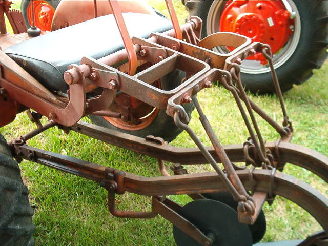 ------------- Like them all, but love the "B"s. |
Posted By: SC_MudDuck
Date Posted: 04 Jun 2020 at 8:58pm
|
So, it holds as it did before. Have to find the sweet spot after setting height, but it takes some finagling. Just can’t pull it back, let it go, and it fall into a neutral position. It’s a manual shift to hold. Watching the video the spring doesn’t compress and the screw above doesn’t seem to do anything. Should it do something and should it compress? Also, if the cylinder is leaking behind the head, what does that mean? |
Posted By: SC_MudDuck
Date Posted: 04 Jun 2020 at 9:03pm
|
This becoming very interesting for sure. Knew I didn’t have a museum relic but wish I knew the story behind the mods. Pretty cool ingenuity, wonder when the mods happened? How many revisions were there to the design before completion, etc. I’ll assume it has a PE stamp or some other stamp of compliance! 
|
Posted By: steve(ill)
Date Posted: 04 Jun 2020 at 9:24pm
|
YEA... Definitely a Professional Job ! You should be able to pull the lever UP and it raise, then LET GO and it pops back to the HOLD position.. You press DOWN if you want it to gravity drop... Normally STICKING in the cam plate / spring area can cause that "finding the sweet spot" .... i have not adjusted one for 10 years.. cant give you good directions now.... but your looking in the right area... You might soak with penetrant and see if that helps any.. the cylinder ROD goes thru the barrel and then there are 3-4 pieces of packing of the VEE chevron type installed... The HEX nut screws in and compresses that packing.. If it leaks, you MIGHT be able to snug it up... If its 70 years old, it might be brittle and not help...... but leak could be the hose or fittings also.
------------- Like them all, but love the "B"s. |
Posted By: SC_MudDuck
Date Posted: 05 Jun 2020 at 8:04am
Is this the right way connect the hoses? If so, I would prefer to connect them properly such that I get the correct applied work out of the system. Also, if the working pressure is 3200psi would I need a 4000 psi gauge or just plug port 6? I do like gauges...
 |
Posted By: steve(ill)
Date Posted: 05 Jun 2020 at 8:23am
|
"Normally" the hoses are TEE together... Looking at the print of the valve i dont see what it hurts to put one hose on the TEST port.. There does not seem to be a restriction or orifice in that line... but im not sure......i think best to have a TEE off one port..... The GAUGE is not standard, just for a test.. You remove the gauge when done and plug with a small pipe plug... You dont want a gauge to get SMACKED and break off when in the field. ------------- Like them all, but love the "B"s. |
Posted By: SC_MudDuck
Date Posted: 05 Jun 2020 at 11:22am
|
I have tracked down all the AGCO part numbers to turn this back to OEM, but have NO IDEA where to find them for purchase. Any thoughts?
|
Posted By: steve(ill)
Date Posted: 05 Jun 2020 at 1:03pm
|
there is a CLASSIFIED section on this FORUM... I would post that you have a B tractor and need ............ I dont know if your talking cylinder / rock shaft / or just hoses... NAPA or someone can make the hoses.. You can also buy small hoses at a lot of FARM STORES that have pipe thread ends...... Im sure there are several on this site that have "PARTS" for whatever you need. ------------- Like them all, but love the "B"s. |
Posted By: SC_MudDuck
Date Posted: 05 Jun 2020 at 1:15pm
|
Was mainly talking all the parts shown in the schematic for the re-routing the lines with a Tee such as below. These part numbers came from the Agco Parts Book so trying to cross reference them is a little tough. Is there a real need to be this thorough for basically a plug using 1/2" NPT fittings? 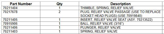 |
Posted By: steve(ill)
Date Posted: 05 Jun 2020 at 3:43pm
|
No....... those parts are internal.. Not coming out.. Take off the hose and screw in a pipe plug with teflon tape to seal it....In the main port, you can run a TEE right off the valve, or run out a foot with a hose, then put a TEE and run each side... 3 hoses. ------------- Like them all, but love the "B"s. |
Posted By: SC_MudDuck
Date Posted: 05 Jun 2020 at 8:08pm
|
Cool...just needed a sanity check. So after soaking last night and all day, then pressure washing again. It appears that the cylinders and valve are working much better. There is a much smoother lift (versus jerky), but the resting neutral position is a little less desirable. Wish there was more response instead of being spongy. Sometimes it returns to hold other times it creeps up and a few times it creeps down and most I have to set. Take away is that holds pressure and nothing is leaking. Will test it out tomorrow on a sprayed area to see what sorta stress it takes. Getting excited! |
Posted By: cdsloop
Date Posted: 05 Jun 2020 at 9:01pm
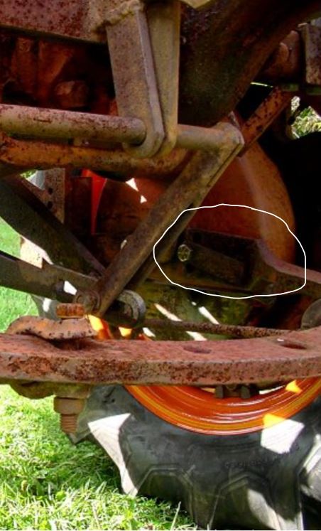
MD, I have a 1950 B as well. I think I see your problem with holding in neutral. 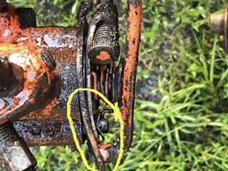 The plate circled should be flat. Someone has fitter rough with the lever, or something hit and bent it. That plate and the one to the right/outside of it should slide next to each other independently. Here is a picture that I took of my valve a few minutes ago. 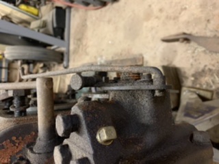 Note that my lever and axle is missing, I’m in the middle of a major repair. But you can see that my plate is flat and not bent like yours. |
Posted By: SC_MudDuck
Date Posted: 05 Jun 2020 at 10:06pm
|
I was starting to think the same way but needed more knowledge. Sooooo...how flat does it have to be? Where can I buy another if I screw it up? I included those plates in my replacement parts list from agco. |
Posted By: steve(ill)
Date Posted: 05 Jun 2020 at 10:17pm
|
Good Catch CD... the plates dont need to be perfectly flat... they just need to move EASILY with respect to each other.. you can move them by hand , full stroke to check... you might be able to bend by grabbing with a pair of pliers instead of just buying new. ------------- Like them all, but love the "B"s. |
Posted By: SC_MudDuck
Date Posted: 05 Jun 2020 at 10:28pm
| Just wasn’t sure if it were tool steel or a punch/cast piece. Initially thinking of a little MC Hammer persuasion but like the finesse work of the pliers assassin. Calculated yet precise!!! Many thanks on this, I’ll you know tomorrow how it goes! |
Posted By: SteveM C/IL
Date Posted: 06 Jun 2020 at 8:11am
|
[QUOTE=SC_MudDuck]Just wasn’t sure if it were tool steel or a punch/cast piece. Initially thinking of a little MC Hammer persuasion but like the finesse work of the pliers assassin. Calculated yet precise!!! Many thanks on this, I’ll you know tomorrow how it goes ------------- Like them all, but love the "B"s. |
Posted By: steve(ill)
Date Posted: 08 Jun 2020 at 4:40pm
This looks quite a bit stronger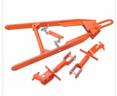 ------------- Like them all, but love the "B"s. |
Posted By: SC_MudDuck
Date Posted: 09 Jun 2020 at 9:28am
|
So it appears I will be re-packing the cylinders, as they continue to leak. As for the 3 pt hitch, that's a major modification that is out of my skillset. May take me some time to make this improvement. Not sure where the factory drawbar mounts to the rear drives.
|
Posted By: chaskaduo
Date Posted: 09 Jun 2020 at 12:07pm
 MOUNTS WITH MOUNTS WITH  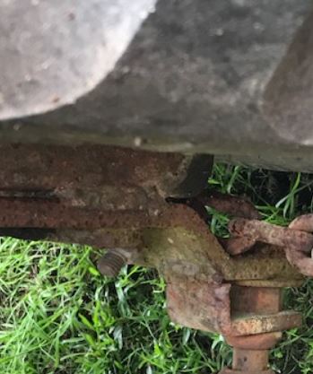 Looks like yours maybe welded to the final drive housing, covering the mounting holes. A stock Drawbar and mounts, $225 + ship on Ebay if nobody here has a better deal. https://www.ebay.com/i/123755114150?chn=ps&norover=1&mkevt=1&mkrid=711-117182-37290-0&mkcid=2&itemid=123755114150&targetid=888709244052&device=c&mktype=pla&googleloc=9019632&poi=&campaignid=9426322072&mkgroupid=92907997622&rlsatarget=pla-888709244052&abcId=1141016&merchantid=113582784&gclid=EAIaIQobChMIr5jJ6Zz16QIVxkXVCh2zhAiQEAQYCCABEgK0A_D_BwE" rel="nofollow - - https://www.ebay.com/i/123755114150?chn=ps&norover=1&mkevt=1&mkrid=711-117182-37290-0&mkcid=2&itemid=123755114150&targetid=888709244052&device=c&mktype=pla&googleloc=9019632&poi=&campaignid=9426322072&mkgroupid=92907997622&rlsatarget=pla-888709244052&abcId=1141016&merchantid=113582784&gclid=EAIaIQobChMIr5jJ6Zz16QIVxkXVCh2zhAiQEAQYCCABEgK0A_D_BwE 3pt setup for stock drawbar is around $400-$500 + ship, includes ram and mounts for it. Sample https://www.ebay.com/i/121320116514?chn=ps&norover=1&mkevt=1&mkrid=711-117182-37290-0&mkcid=2&itemid=121320116514&targetid=882904020427&device=c&mktype=pla&googleloc=9019632&poi=&campaignid=6469981122&mkgroupid=86285324342&rlsatarget=pla-882904020427&abcId=1141176&merchantid=8576394&gclid=EAIaIQobChMIgtXW-qH16QIVE9bACh2M7wa0EAQYAyABEgKHifD_BwE" rel="nofollow - https://www.ebay.com/i/121320116514?chn=ps&norover=1&mkevt=1&mkrid=711-117182-37290-0&mkcid=2&itemid=121320116514&targetid=882904020427&device=c&mktype=pla&googleloc=9019632&poi=&campaignid=6469981122&mkgroupid=86285324342&rlsatarget=pla-882904020427&abcId=1141176&merchantid=8576394&gclid=EAIaIQobChMIgtXW-qH16QIVE9bACh2M7wa0EAQYAyABEgKHifD_BwE ------------- 1938 B, 79 Dynamark 11/36 6spd, 95 Weed-Eater 16hp, 2010 Bolens 14hp |
Posted By: steve(ill)
Date Posted: 09 Jun 2020 at 12:19pm
|
each final drive has two holes for mounting a drawbar or cross bar. One hole is threaded and one is not. The bracket CHASE shows above pilots into the final drive case and the "hole" is to stick a 5/8 inch bolt thru and bolt into the final.. you would have one bracket on each side... when mounted, the bracket looks something like this. actually, if you look close, there are TWO holes in front of the axle and TWO holes behind ( which have the bracket in them) on each side.  ------------- Like them all, but love the "B"s. |
Posted By: jlbintn
Date Posted: 11 Aug 2020 at 10:15am
|
This is a great thread, lots of good links with good information. I am on the same road as the OP, only further behind, working to get my hydraulics functional. I know the pressure specs for the pump (3200 psi). I will probably have to have the hose made. What size should the hose be, outside diameter specifically. I called around yesterday to get some feelers, and that was one of two questions I got, the other being the connections at the ends. |
Posted By: Jt s. candycane
Date Posted: 15 Aug 2025 at 1:38am
| Where can you get allis chalmers b hydraulic cyclinder rods at I need a few |
Posted By: steve(ill)
Date Posted: 15 Aug 2025 at 9:23am
|
https://www.ebay.com/itm/265484488899%20" rel="nofollow - https://www.ebay.com/itm/265484488899
------------- Like them all, but love the "B"s. |
Posted By: Jt s. candycane
Date Posted: 15 Aug 2025 at 2:32pm
| That link dosent work ?? |
Posted By: JoeM(GA)
Date Posted: 15 Aug 2025 at 2:59pm
|
lets try this - https://www.ebay.com/sch/i.html?_nkw=265484488899+&_sacat=0" rel="nofollow - https://www.ebay.com/sch/i.html?_nkw=265484488899+&_sacat=0 ------------- Allis Express North Georgia 41 WC,48 UC Cane,7-G's, Ford 345C TLB |