7000 Series Battery Cable Routing
Printed From: Unofficial Allis
Category: Allis Chalmers
Forum Name: Farm Equipment
Forum Description: everything about Allis-Chalmers farm equipment
URL: https://www.allischalmers.com/forum/forum_posts.asp?TID=153950
Printed Date: 02 Sep 2025 at 9:52pm
Software Version: Web Wiz Forums 11.10 - http://www.webwizforums.com
Topic: 7000 Series Battery Cable Routing
Posted By: GM Guy
Subject: 7000 Series Battery Cable Routing
Date Posted: 13 Sep 2018 at 7:09pm
|
Hey all, Still working on the 7040, putting new battery cables on, and I am making them myself, using 2/0 cable for the main lead to starter, and Group 31 threaded stud type "truck" batteries. Proper terminals and a hydraulic crimper. I am having trouble with when I close the battery tray, it wants to pinch the cable at the ground bolt on the side of the transmission case. I currently have the batteries sitting "normal" (grounds front and rear, positives middle) I have the cable eyelet crimped on and on the rear battery stud. I have it held by a harness/hose holding clamp held by the 5/16 carriage bolt at the square hole on the top of the tray. ( I believe this is the factory setup) I have the cable behind/ inboard of the hinge pin and free from the front ground cable (versus trapped between cable and tray), then it's draped over the bellhousing, runs in front of the clutch valve, and down between the starter and the block. I have a rearward pointing 90 degree terminal for the starter that I will crimp on when I get my cable length dialed in. So I ask you, how do you route this so it doesn't pinch, and lays "right" ? Is there only that one clamp, or am I missing another? I would like to know what the factory routing is, unless it is a poor route and a better one exists. Pictures would be awesome if not much trouble. Any input appreciated, Thanks! ------------- Gleaner: the properly engineered and built combine. If you need parts for your Gleaner, we are parting out A's through L2's, so we may be able to help. |
Replies:
Posted By: LB0442
Date Posted: 14 Sep 2018 at 10:03am
A while ago I put new batteries and cables on one here. I bought a 3/0 positive cable off eBay several years ago and used that for this. Just had to shorten the end for the starter. I use the solder pellets and solder terminals with the heat shrink that has glue in it. I also replaced the 6 gauge to the main power breaker.  On the negative side I used 2/0 for each battery but then they were too stiff to put in factory location so I welded a bolt in for each. The factory originally had braided cables for each negative and then another braided to connect to the chassis. The big issue I was concerned with was any electrical needs a complete circuit. That braided cable from the tray to chassis is probably the weak link in the whole setup as it is just 2 gauge. It does spin it over really fast, no problems though.  |
Posted By: Ron(AB)
Date Posted: 14 Sep 2018 at 6:41pm
There is a "U" shape behind the hinge for the positive cable. Sorry it is hard to see ... but the step stopped the tray from swinging out.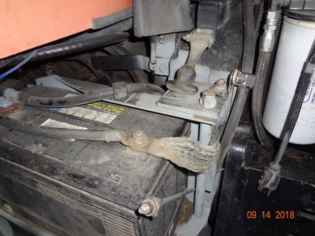 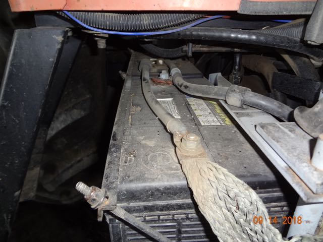 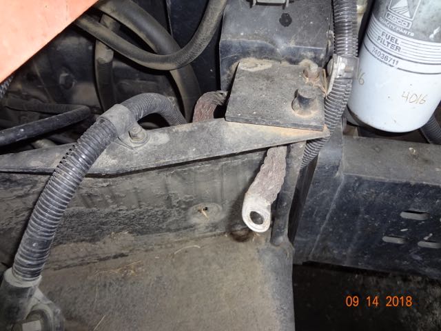
|