Calling Dave Kamp
Printed From: Unofficial Allis
Category: Allis Chalmers
Forum Name: Farm Equipment
Forum Description: everything about Allis-Chalmers farm equipment
URL: https://www.allischalmers.com/forum/forum_posts.asp?TID=132398
Printed Date: 18 Dec 2025 at 1:59pm
Software Version: Web Wiz Forums 11.10 - http://www.webwizforums.com
Topic: Calling Dave Kamp
Posted By: desertjoe
Subject: Calling Dave Kamp
Date Posted: 08 Dec 2016 at 9:23pm
|
Hey Dave Kamp,,,Ya there,,??? Well,,some weeks ago,, I had finally decided I was finished with the Industrial D14 Backhoe/ Loader. The engine you hauled across several states has worked out many wonderfuls,,,,runs like an Allis and starts with one pull of the choke rod,,,,,  There is one issue with the tractor tho,,,,,,and I'm bettin you got a suggestion that will help me. It is nearly IMPOSSIBLE to turn the wheel when you have even a half load of dirt in the bucket,,!!! The power steering pump that I had for the engine turned out to have excessive wear from tooth contact to housing. I bought another pump but it was not much better with too many miles. I contacted a gear Mfgr and was given an estimate of WAY more than I felt was reasonable. The BH/L are fed by a crank driven Cessna but I have no clue what it's specs are as there are NO numbers anywhere on the pump. I have got a suggestion to maybe "T" into the discharge line off the cessna and route to the D14 power steering system and just bypass the D14 pump altogether. The 3 lines to/from the pump could be routed with hydraulic hoses at a cost of bout $150,,,but again,,I have no clue if the Cessna would even work there. I am to the point of seriously looking for another complete front end assembly off a "something" to take the place of the Allis front end. I know this is your specialty ,,,and,,I got my pencil and paper ready,,,,, |
Replies:
Posted By: DaveKamp
Date Posted: 08 Dec 2016 at 11:49pm
|
Hi Joe! Okay, so for the tractor... is it a NF or WF tractor? If you're running a loader and it's NF, I would certainly recommend going to a WF setup, to improve safety and stability. Next, if you want this thing to be a genuine worker, you're gonna need power steering in the front end. I don't recall if yours had any sort of power steering, but based on your question, I'm betting it don't... or if it does, it ain't workin'. A loaded bucket demands a strong axle and serious power steering in order to really work hard without killing the operator's arms. Tell me more about what you got, and post some pictures of the setup. ------------- Ten Amendments, Ten Commandments, and one Golden Rule solve most every problem. Citrus hand-cleaner with Pumice does the rest. |
Posted By: shameless (ne)
Date Posted: 09 Dec 2016 at 2:34am
| JOe...I ran lots of WD's with loaders (farmhand) and no PS. just gotta grease them good and be moving when turning. also when I was first chasing my old lady.....oooops....I mean my loving girlfriend, her dad had AC's and their power steering came from Buicks of the 70's era. said they'd last about a year with heavy use, then would hafta replace them, and were easy to find and cheap! you know....CHEAP! |
Posted By: Dan73
Date Posted: 09 Dec 2016 at 5:51am
|
Dave Joe is asking about his d14 industrial backhoe. So yes it is a factory wide frontend with power steering. The issue is with a ts500 loader that front end just don't turn good. I have the same problem with my d15 industrial. I have not tested the pressure built by the power steering pump but like Joe I don't know what it should be. From what my uncle saids about the d14 they bought new years ago mine is working normal or close to it but once you fill that bucket getting out of the barn is tricky.... As Joe said getting one of the power steering pumps rebuilt is crazy expensive. That is why I suggested replacing the pump with a priority flow valve off the hydraulic pump running the loader. That would allow Joe to use the cheaper pump he has that works. I have wondered if there is a safe way to increase the force turning the tires. My concern is of course that I don't want to put a bigger cylinder in only to break something else. |
Posted By: desertjoe
Date Posted: 09 Dec 2016 at 7:13am
|
Hey Dave,,,yeah, it is a factory Industrial D14 as it has the reinforced W/F axle to address the added weight on the front end. Like ole Greg says " Pump pressure equals power, and pump flow equals speed" ,,,and the D14 factory steering cylinder looks to be too small for the additional weight that the loader puts on the axle, and the D14 power steering system being built the way it is,,,I see no reasonable way to modify or add an additional cylinder to it like ole Greg did to his D19. This is why I thought it may be cheaper,,(yeah, Shameless,I know,,) to look for a donor tractor with a stronger and simpler power steering system,,,,???? (and even a Ford) I do have a generator/power steering pump that came off my 1955 Chevy but have no clue what kind of pressures or flows it puts out,, prolly not enough of either,,,, OK,,Shameless,,,I want to see pics of the Buick steering on them FIL's tractors,,,,,  |
Posted By: shameless (ne)
Date Posted: 09 Dec 2016 at 7:30am
| can't Joe....he died, and that tractor is long gone somewhere |
Posted By: Dan73
Date Posted: 09 Dec 2016 at 9:06am
| Joe I was thinking of taking the lines that go to the steering cylinder and plumbing them into a new cylinder that is in place of the rod going to the tires or something like that done right on the back side between the tires so you have more room for modification. I haven't gotten any good design ideas yet. My favorite store has a section of steering cylinders that I was thinking about. What you need is a cylinder that has a rod comming out each end and you mount the cylinder fixed so both tires move at the same time on the same cylinder. As I said I don't have a design just a concept. |
Posted By: Dan73
Date Posted: 09 Dec 2016 at 9:09am
| The old farmall wide front ends I have seen have a rod connecting the two tires and the wheel turns one tire the connecting rod turns the other tires maybe something like that could be made to work on the back side of the stock front end. |
Posted By: Gerald J.
Date Posted: 09 Dec 2016 at 9:21am
|
I made the loader easier on my MF-135 power steering by changing the front tires from 6.50-16 to 11L16 wagon tires. The bigger tires had less pressure on the ground per square inch with their bigger foot print and didn't cut grooves in worked ground. Not cutting grooves made them easier to turn. The miniature ribs surely helped that too. The wider tires took new 10 inch wide rims with a couple inch offset. I found one at a rim store in Des Moines and the second one at a tractor salvage at Colfax, IA, the one along the river that went out of business since then. That MF236 loader was too big for the MF-135, a full bucket of gravel would not rise, the tractor rears rose instead. In snow a full bucket of snow would rise until a tire chain fell off, then even dumping the load wasn't enough to have traction. The front axle of the MF-135 has been welded at least once from a lifetime with that loader. I moved that loader and those front tires to my JD gas 4020 with a mount that I designed and had built. I found the wagon tires were poor for field work especially cultivating and rotary hoeing because it could take considerable over steering at 10 mph to get the tractor to change direction, so I went to 4 rib 11.00-16. The bigger tires I figure are easier on spindles even in plowed ground because they don't fall into furrows so deep. With the wagon tires on the MF-135 when working alfalfa, actually I could stop the tractor and back up and the alfalfa would stand back up a sign of the low pressure from spreading the load over a larger foot print. Should help but might not be the complete solution for a worn out power steering pump. There have been aftermarket power steering systems built for AC tractors, might be easier to find than a good pump. Gerald J. |
Posted By: Dan73
Date Posted: 09 Dec 2016 at 9:30am
| The tires will help. I mounted a pair of 265 tires off my pickup on the rims of my d15 helps alot with cutting in like you said. But even in my barn with wet cement cleaning it out it is hard to turn. I hit my poor 250 or so year old barn the other day and felt bad fixing the old post I knocked down. |
Posted By: Dan73
Date Posted: 09 Dec 2016 at 9:43am
|
https://www.surpluscenter.com/Hydraulics/Hydraulic-Cylinders/Power-Steering-Hydraulic-Cylinders/2x8x1-25-DA-DOUBLE-ROD-HYD-CYL-9-6845.axd" rel="nofollow - https://www.surpluscenter.com/Hydraulics/Hydraulic-Cylinders/Power-Steering-Hydraulic-Cylinders/2x8x1-25-DA-DOUBLE-ROD-HYD-CYL-9-6845.axd Joe I was thinking about something like this in place of the rod a that connect tires to the pivot on the tractor but I have not gotten beyond thinking maybe it would work. |
Posted By: DaveKamp
Date Posted: 09 Dec 2016 at 12:22pm
|
Okay, let's start from the beginning: Loaders present several interesting additional stresses on a tractor. First, is obvious- more weight on front tires, which causes more turning frinction... 'scrubbing'... This translates to increased load for turning. As others noted, if you're rolling, the turning load is greatly relieved, because you're actually only scrubbing 'part' of the tread contact surface as you turn the wheel. Second, the tires, having more ground pressure, will sink in sooner, and deeper than they did with less pressure. How much? Depends on two factors... first... tire pressure. If you put 10psi in a tire with 10 square inches of ground contact, that's 100 pounds of support. Put 200 pounds of weight on the tire, it's gotta find another 100 square inches of support area. Take some eyeball measurements of your unladen tire's contact patch, and put a pressure gauge on the stem, do some pencil-scratching on paper to see where you are in REAL LIFE... and then get a big bucket of gravel lifted up, and repeat the process, you'll see what's happening in your application. Next... steering geometry. If you ever wonder why your tires looked like they had a 'lean' outward at the top, you're gonna find out quick. One would think that a tire that's perfectly perpendicular to the ground would be the most sensible alignment, but that only works when a machine doesn't have to turn with grace. We take for granted that sars on the road get aligned by professional service techs per engineer's specifications and everything works like magic. The numbers they work with are based on a myriad of factors, along with terms like Ackerman Angle and Roll Center, Crown, Aspect Ratio, and stuff. Now let's skip the auto-tech and change to agricultural/heavy equipment mode, where there's some simpler considerations. Look at the spindle. See the axis where the wheel pivots as it steers? The tire changes it's angle to steer there. Imagine that tire, instead of being where it is, was about two feet out further from the tractor... out hangin' on a stick. Call the spindle's pivot the Kingpin (even if it's not). Now put a heavy load on the axle, where's the highest strain? Well, it's on the point where the spindle meets the kingpin... and of course, there's lots of strain on the kingpin, too. It's because the tire's contact point is WAY, WAY out from the pivot axis of the spindle... far from the kinpin's pivot point. Let's say you were to drive that funky-spindled thing, and drop one tire into a hole, or bump into a tree. Where's the shock force of that bump go? Right through the steering rod. Why? Because there's a ton of leverage from that wheel hangin' out three furrows. Move that wheel inward, so that it's contact point is really, really close to the kingpin axis, and all those funky forces go away. (try to expain this to the punks who drive 'squash-bug cars with 'fart' mufflers... but don't hold your breath- you can't fix stoopid). ---Flip to pg217 in your Geometry textbooks, we'll revisit this later Ever notice how some tractors, like the Allis B, C, CA, the Ford N, Case VAC... how they have steering boxes mounted to the chassis, and drag links that go forward to some pivot point near the axle, then another link goes to either one knuckle, or the tie rod between wheels? If you have one of those tractors, jack up the belly, so the front axle is off the ground and able to wobble right left, free. Grab one wheel, and wiggle it, watch the steering wheel. Feel sloppy? Look at the linkage. There's slop between wheel and wheel bearing. Slop 'tween knuckle and axle, slop in the tie rod end. Slop in the drag link, pivot, and other tie rod, all the tie rod ends, steering box, and lastly, the wheel worm. Ever wonder why the old NF Farmall wanders down the road like a drunk with ADHD looking for a half-used cigarette? Start eliminating slop, one piece at a time... there's a ton of places for it to party. But once you get it all tight, repeat the task... and when you do, take a ratchet strap and lock the steering wheel down so that it CANNOT turn. Swing the axle from full down on one side, to full up, and observe the tire angle. You'll notice that from full down, to full up, that the tires actually CHANGE ANGLE. That's because the steering linkage is not perfectly on the same axis as the axle pivot point... it's swinging around, and to accomodate the changing distance in that swing, the tie rod, etc., all has to move to compensate. Also consider for a moment... you have a steering box pushing forward and aft... and it's pushing on a knuckle connected to the end of an axle. If there's slop in that axle pivot, not only are you trying to pivot a tire, you're pushing one side of the axle forward and back. Now drive down the road with little or no steering input, that axle's wandering fore and aft, and that changes the tire angle... you have what Jeep guys affectonately refer to as 'death wobble'. It doesn't take too much thinking to realize that sloppy, erratic, unpredictable steering is something that makes accurate machinery operation very tiring and frustrating. Thing is, when your'e actually DOING it, you don't notice it- you just get angry and tired. Like having a cockleburr stuck in your waistband... --- Back to knuckle geometry --- IF you consider that the knuckle offset effort, along with the articulating (swinging) axle variation and all the slop encountered with a complex mechanical steering linkage, it's not hard to understand how rolling over a lump, or through a hole, with a common tractor could wind up whipping the steering wheel and busting your thumbs and fingers. Put another thousand pounds in a loader bucket that's a 500 pounds, hanging out 48" past the front of your front tires, and a ton of counterweight on the back, and tell me how important it is to have good steering on a tractor. --- Open your service manual for your favorite WF tractor... look at the axle --- If you wanted to make the steering on your tractor the least sloppy, and the least reactive to holes in the ground, and the least reactive to axle articulation, you'd do everything you could to keep the reaction loads simple. There's a reason why the steering of a Model A Ford is no longer popular... we have rack-and-pinion... and although it seems a whole lot more complex, the geometry and reaction loads are a whole lot SIMPLER. No Bump Steer. Fat tires will keep ground pressure low, and Fat tires reduce sinking in deep, which in many cases, means the tire is stuck in a crack that NO steering force within reasonable planetary loads will overcome. Unfortunately fat tires frequenly come at the expense of wheel offset- farther from the pivot axis. IF you have a rim/tire combination that gives you twice the tire surface, without moving the rolling centerline any farther away (or better yet, moves it CLOSER to the axis of the kingpin), then you're golden). Next, remove the steering linkage mess. Remove the axle's pivot axis from all the steering problems. The two front wheels are connected together with a tie rod. Put two hydraulic cylinders up there. One end of each on the axle, other end on each knuckle. Steering forces are now 'isolated' to being between the axle and the knuckle, no where else. Front axle pivot sloppy? No big deal. ---A Reading The Second chapter of the book of Farmall: --- Do tractor manufacturers do this? Not often. Why? Because it usually complicates having front axle adjustability. The other thing tractor manufacturers don't do, is build front axles that are beastly strong with respect to supporting intense axle pivot loads, or span loads for the front axle. Why? Because it's a farm tractor, not a forklift truck. It's gotta be adjustable, and it's gotta clear crops, so having a beastly front axle isn't directly compatible with it's intended purpose. You can try a vareity of 'fixes' to improve the steering and durability of a stock axle, but IF you really, really, REALLY want it right, sit down with a piece of pizza, a beverage, and a pad of paper and pencil, and start scratching out drawings.. Next up... Power steering, in a nutshell... or a nuthouse... ------------- Ten Amendments, Ten Commandments, and one Golden Rule solve most every problem. Citrus hand-cleaner with Pumice does the rest. |
Posted By: DaveKamp
Date Posted: 09 Dec 2016 at 1:00pm
|
So there's two types of fluid power systems: Pneumatic, and Hydraulic. Pneumatic employes pressurized gases, Hydraulic uses pressurized liquids. What's the diff? Gases are compressible. Liquids aren't. Of course, oil is a liquid. Water, provided that it's not below freezing temperature, is a liquid. Oxygen, provided it's not at stupid-below-zero temperatures or in a bomb-shaped pressure vessel, will present itself to us as a gas. LEAD, when it's above 800F, and IRON when it's above 2100F or so, are both liquids, and Mercury... oh yeah... it's a really, really nice liquid basically all the time. If you're wondering what Mercury is really, really good for, look up MERCURY BEARINGS in lighthouse applications... WAY, WAY cool. Pneumatic systems... well, the most common type, is AIR... which is technically about 21% oxygen, 73% nitrogen, and all but the last 0.04%, is other misc gases like argon, helium, xenon and stuff. That wee, wee 0.04% is a 'deadly greenhouse gas' that plants desperately need to survive... it's called 'carbon dioxide'... so be really careful with that stuff. Hydraulic systems... they frequently use oils, but it's not unusual to see water, or even liquid metals (did I mention Mercury? sorry, it's a serious environmental hazard, so I'm not allowed by the State of California to whisper it anymore...) I'll bet that nobody ever told you that Your outdoor thermometer is a fluid-power hydraulic-over-pneumatic indicator device, who's primary operating principle is THERMAL EXPANSION OF A LIQUID METAL. Yeah. It's also an environmentally-friendly gadget... requires NO EXTERNAL POWER SOURCE, no toxic-metal batteries to discard into the landfill every six months... no liquid crystal display or lead in a circuit board, but i digress... Anyway, when you build a fluid power system, it's extremely important to keep liquid and gaseous systems separated. IF you introduce liquids into a pneumatic system, it becomes HYDRAULIC. If you introduce gases into a hydraulic system, it becomes PNEUMATIC. Oh, and ---if you introduce oxygen, into a hydraulic system that uses a combustible fluid, you have a DIESEL ENGINE. [Read up on Rudolph Diesel in your spare time, and you'll understand why) ---If you introduce a liquid, that can turn into a solid, into a hydraulic system, you have traumatic failure. Today is a good day to pull the plug on your hydraulic reservoirs and dump out whatever water may be hiding in the bottom. Now, there's three basic types of hydraulic systems... as defined by the PUMP TYPE. They are: FIXED DISPLACEMENT. Turn a shaft on a pump, and for each revolution of the shaft, a MEASUREABLE amount of fluid WILL COME THROUGH. A gear pump, or a fixed-displacement piston pump, are examples. The oil pump in the oil pan... is a fixed-displacement pump. Volume going out, is determined by how FAST you spin it. VARIABLE DISPLACEMENT. Turn the shaft on the pump, and depending on circumstances, you'll get high flow, others, you'll get low- or no-flow. The primary example of variable displacement, is a movable vane-type power steering pump. As the pump spins, the vanes are pulled outward from center by centrifugal force, and they push oil outward at a pressure and volume determined by load. When the load reaches a certain pressure, the vanes retract, and will send forth no more pressure, but will accomodate any flow up to the pump's maximum flow rate. Since Air is also considered 'fluid', we can draw parallel for sake of description. A piston-style air compressor, and a ceiling fan both move AIR. The compressor is a 'fixed displacement pump'. A ceiling fan, however, is 'variable displacement'. If you block the airflow coming into, or out of the air compressor, it will keep trying to suck in, and force out, until the motor stalls, or it swallows your necktie. The ceiling fan will just thrash the air around in a circle and get hot. The third type of hydraulic system is called "HYDROSTATIC", and it's a bit more interesting, and I'll leave all of that for later, but for now, a 'hydrostatic' system, is one where the pump is a fixed-displacement type, BUT, the displacement can be VARIED. Deep? Don't worry, I'll blow up that bridge when I get to it. Time to go teach class, Ill be back tonight for the next episode. ------------- Ten Amendments, Ten Commandments, and one Golden Rule solve most every problem. Citrus hand-cleaner with Pumice does the rest. |
Posted By: Gerald J.
Date Posted: 09 Dec 2016 at 6:13pm
|
Model A steering box I believe is a worm gear. My dad built a garden tractor using one along with lots of other model A parts and I don't remember it kicking when hitting things. Now the Model T steering is by spur gears and kicks a lot. Also the 9N and 2N tractor steering boxes were bevel gears and kicked hard. The 8N went to a ball worm and cured that kick. I'll check that model A steering box next time I'm at the farm, if I remember it. Gerald J. |
Posted By: Ted J
Date Posted: 09 Dec 2016 at 7:19pm
|
Dave, where the heck have you been?? I've missed ya! Both you and Danny Raddatz haven't been on here since October...... Nice to have you back!! ------------- "Allis-Express" 19?? WC / 1941 C / 1952 CA / 1956 WD45 / 1957 WD45 / 1958 D-17 |
Posted By: DaveKamp
Date Posted: 09 Dec 2016 at 8:31pm
|
A hydraulic system of the simplest type, consists of three components: An input, which is typically a pump, but could be a piston in a cylinder... Plumbing, to connect it to a load... An output, which could be a cylinder, a motor... or anything else someone dreams up. A more complex system will have a pump, a reservoir, some filters, a valve or two, some plumbing, and several cylinders, motors, etc., But here's the basic property of a hydraulic system: Pressure of a fluid, has the abilty to generate force. IF you move a VOLUME of fluid, that force can be continued over a DISTANCE. From 5th grade science, in SIMPLE MACHINES, you learned that Work is the result of applying force, over a distance. Work = Force * Distance. Let's say you lift a 10lb load 10 feet. that's 10 x 10 or 100 foot-pounds That's a fair amount of work, right? Now, work can be done in a second, or a minute, or an hour, day, month, year, or eon. I'm gonna pick on Joe. Let's Joe takes a day out of his busy schedule to lift that 100 foot-pound load. I'm not being mean here... Joe's put in his fair share of time supervising the back end of a shovel, he's no spring chicken... needs to take it easy on his back, okay? But my daughter is a soccer goalie... she's young, energetic, and quick, and she's strong for being 12 years old. She will take ten minutes to do it, because she'll do it a half-pound at a time, tossing 'em up underhand. I'm gonna do it in four seconds,'cause I can flip that 10-pound box up there with one hand. I've got a small-block chevy sitting on the floor, with a belt on it's crankshaft, and I can set that 10 pound box on the belt, and it'll chuck it up there in a fraction of a second... What JOE does in a day, my daughter can do a hundred or more times. I can do it several thousand, but that small block chevy can throw THOUSANDS upon Thousands up there in the timespan that anyone else would get just a few. What's the difference? Power. Power is force x distance X TIME. Since I can do it faster, I can do it MORE than my daughter, and more than you. The engine has even more on tap. Easy, eh? Now 'm gonna throw in one more thing: Duty Cycle. Joe can sip coffee, read the newspaper, and do one a day, and if he lived a million years, doing that 100 foot pound lift once a day, every day would likely not even be enough to keep him in shape. My daughter would be perfectly fine with flinging them for six hours, but I'd have to take her out for ice-cream when we were done. I'd probably be able to do several days of sixteen hour shifts, with a water break every few, of course. The 350 chevy would blast us all off the planet, but did I mention that there's no cooling system on that engine? Yeah, it'll throw a mess'a boxes, but eventually, it's gonna overheat and seize... so either I shut it down to cool for two hours between 15 minute sessions, or it turns into liquid metal. (remember... liquid metal?) This is what we call DUTY CYCLE. How long a device can operate at a given POWER LEVEL, without having to COOL DOWN. When something is rated for 100% duty cycle, that means it is designed and INTENDED to survive at that power level, WITHOUT STOPPING... EVER. Now, I'm a hard-a$$ when it comes to designing things. I like things built to 200%... I like 'em to be able to run continuous duty, in a state of OVERLOAD... forever. Call me crazy, and your're probably right, but I don't like stuff that breaks... and I don't like stuff that overheats, falls apart, or wears out fast. Power, is the ability to push a certain amount of force, a certain distance, in a certain time. Duty cycle, is how long something can develop that power, before it needs to rest. Doing little improvements, like taking a bull-whip to Joe's back, might increase his productivity. Bringing my daughter ice-cream and offering her a pair of goalie gloves and a new kitten would step up her game. Offering me shares in a fast-growing major company would get my attention, and the small-block chevy would benefit greatly from the addition of a good cooling system. EACH one of these will have a positive improvement on productivity, and SURVIVAL. Survival is important... and there's two terms I"ll mention here, because they're related: Mean Time Between Failure... aka "MBTF". That's how long something can be expected to run under expected service ratings, before it's gonna die. Mean Time Between Overhaul... MTBO... how long it'll run under expected conditions, before it wears to the point that it needs an overhaul to continue at it's original design performance standards. So when you're thinkin' design, keep in mind: Work= Force*Distance Power = Work * Time Duty Cycle = Percentage of survivable operation at a given power level. MBTO = how long 'till you'll need to rebuild MBDR = how long 'till it's junk. Shall we get back to hydraulics? Sharpen your pencils, and bring calculator to class... ------------- Ten Amendments, Ten Commandments, and one Golden Rule solve most every problem. Citrus hand-cleaner with Pumice does the rest. |
Posted By: DaveKamp
Date Posted: 09 Dec 2016 at 10:13pm
|
CYLINDERS 101. The simplest element of hydraulics for a person to understand, is the cylinder. As it sounds, you've got a tube, with a piston that slides up and down, there's a rod connected to the piston. When you force fluid into the cylinder, it displaces the piston, and forces it to extend the rod outward. Cylinders which work this way, are called 'single acting'... because they only push. Of course, if there's a valve in-line with the cylinder's port, you can close the valve, and the cylinder will HOLD, because fluid will be trapped between cylinder and valve. This assumes, of course, that the valve and plumbing is strong enough to withstand whatever PRESSURE may appear in the cylinder. Some cylinders have seals on the rod, and a port in the bottom that allows the piston to RETRACT as well. This is called a 'double acting' cylinder. I'll tell 'ya more about 'em in a minute. The amount of force that a hydraulic cylinder can exert, is determined by THREE circumstances. First, is the amount of PISTON SURFACE which the fluid acts upon. Second is the MAXIMUM PRESSURE by which the fluid is introduced into the cylinder. Third is simply wether the cylinder's design is capable of withstanding all the forces involved. Time for MATH! Back while you were fast-asleep in Geometry class, the teacher explained to the pretty girl behind you that the area of a circle could be calculated by knowing some basic dimensions and a very special number called Pi. The name Pi, is actually a shorthand nickname for a Greek dude named Pythagoras, who was actually the Greek God of Triangles. He was a strangish dude with a pet Hypotenuse. His Native American friend was SohCahToa, and they all hung out together and played with numbers. Pythagoras decided to make our lives simple, and told us that if we wanted to build stuff, that most of the world's problems could be solved just by dialing his number... 3.141592653589793238462643383279502884197169399375105820974944592307816406286 Now, if you expect to live a happy and 'normal' life, you'll just knock it down to 3.14 and call it good. (If you're an astrophysics engineer, you're reading the wrong tutorial, just please go away.) Pythagoras granted us some basic thoughts. The first of which, is that there's really only two things you can count on in this world... the first, is gravity, and the second, is triangles. Cats not so much, but gravity and triangles. The next thing you can count on, is your fingers and toes. Most people are accurate to 20, I'm stuck with 19, but I was fortunately blessed with a way to improvise, but don't ask. So let's say you've got a hydraulic cylinder you've liberated from an old dump wagon. It has a bore of 3", and from collapsed to fully extended, it changes by 48"... and the rod sticking out, is 1.5" thick. Let's figure out what this thing is capable of. We know that a hydraulic pump puts out a certain amount of pressure... let's say our proposed system is good for 2500 PSI. What does that mean? That means for every SQUARE INCH of surface that fluid is in contact WITH, there is 2500 pounds of FORCE AGAINST IT. This doesn't matter if it's a hydraulic piston, or a hose, or a threaded fitting. So to figure out the force capability of the cylinder, we're gonna need to know what the piston SURFACE AREA is. 3" bore means it has a radius of 1.5". Our Greek God says A=Pi*R*R. That means Area of a circle can be calculated by multiplying the circle's radius times itself, then times 3.14. In the case of a 3" cylinder, that's a radius of 1.5". 1.5*1.5*3.14=7.065 square inches. I'm not building a rocket here, so I'm gonna call it good at 7 square inches. Multiply that by our projected system pressure of 2500psi, and we get... 2500*7 = 17500lbs. Really? That's like... almost nine tons! Yeah. Look at an average log splitter. Let's say you want more force. Up the system pressure to 3500psi, and you got 3500*7 = 24500lbs... over 12 tons. Let's say you REALLY want more force... go to a 4" diameter... that's 2*2*3.14= 12.56 square inches. Round it to 12.6 'cuz I'm stoopid enough. At 2500psi, that's 2500*12.6=31500lbs... almost sixteen tons. At 3500psi, that's 3500*12.6= 44100... 22 tons. Good log splitter? Not so fast... because this is only half the story... Now, we've determined how much FORCE a 'theoretical system' can generate... but this cylinder, in order to do WORK, needs to be able to generate DISTANCE. Our first cylinder, 3" diameter, had 7 square inches of surface. The travel length of the cylinder is 48"... in order to figure out what it'll take push that piston to full length, we're gonna need to calculate VOLUME of the cylinder... (that's "displacement"). Volume of a cylinder is area x length... so 7*48 = 336 CUBIC INCHES. Let's do that same math on our 4" cylinder... 12.6 x 48" = 604.8. Everybody get about 605? yep, almost twice as much fluid required to extend that bigger cylinder. Another important number to remember (you did remember PI, right?) Tattoo on the back of your eyelid the number 231. Buick made a groovy little odd-fire V6 called the 225, and in the mid 70's upped it to 231ci, turbocharged it to the sky, then later named it the 3.8L... stuffed it into the Regal Grand National GNX. It stomped the heck out of EVERYTHING. If you wanna drool, check this out: https://www.youtube.com/watch?v=k1Nz6KBvrUg Back to reality: What's the number 231 or 3.8 good for? 231 cubic inches = 1 gallon. That 336ci cylinder, divided by 231, comes out to 1.45 gallons. The 605ci cylinder = 2.61 gallons. Obviously, one of these cylinders is gonna take more fluid in order to go from fully retracted, to fully extended, and thus, the VOLUME that the pump moves, is going to determine how quickly the cylinder can act. Time for a 'gotcha'... The cylinder you'd use on a log-splitter, needs to be DOUBLE-ACTING... that means, it not only extends by hydraulic force, it also RETRACTS by hydraulic force... because there's a volume and seals on the BACK side of the piston. The gotcha, however, is that since there's a ROD there, the surface area on the back side is somewhat less than the front. This means that our retraction force will be somewhat LOWER, and our volume required to retract will be correspondingly LESS. As I noted previously, the rod is 1.5" thick. To figure out what the BACK SIDE displacement is, we figure out how much rod area is, and simply subtract it from the front-side area, and then multiply the stroke length. Rod diameter = 1.5", so radius is 0.75. Multiply 0.75 x 0.75 x 3.14 to get 1.76625... Sanity says 1.77 will work... In the small cylinder, that means our retraction surface is 7 - 1.77 = 5.23 square inches. In the large cylinder, that means our retraction surface is 12.6 - 1,77 = 10.83 square inches. Small cylinder retraction force at 2500psi is 2500*=5.23=13075... and 3500*5.23=18305. Large cylinder retraction force at 2500 is 27075, and 3500 is 37905. The next 'gotcha', is that since there's less displacement, it takes less VOLUME to retract. Small cylinder, 5.23 square inches *48" stroke = 251ci or 1.08 gal. Large cylinder, 10.83 square inches *48" stroke = 519.84ci or 2.25 gallons. Obviously, because of the difference of volumes, the cylinder will require more TIME to extend than retract... because it takes more fluid to extend, than retract. Have I tired you out yet? Wait- there's more! Let's say you hook that small cylinder up to a reservoir, pump, and valve, for a log-splitter application. When retracted, the rod side needs 1.08 gallons.. but the main side is basically empty. When it's fully extended, the 1.45 gallons. What this means, is that your tank, when full, and system totally bled, will be LOWER IN LEVEL when the cylinder is extended, than when retracted. It will be approximately 1.45-1.08=0.37 gallons LOWER in level. Notice I said APPROXIMATELY. Why? Because Hydraulic Fluid expands when it's HOT. Ah, time for a bathroom break. Everybody take a fifteen minute break, but be back in here and ready in five, cuz I'm not paid by the hour. ------------- Ten Amendments, Ten Commandments, and one Golden Rule solve most every problem. Citrus hand-cleaner with Pumice does the rest. |
Posted By: DaveKamp
Date Posted: 09 Dec 2016 at 11:24pm
|
So on to Pumps. As I noted, Hydraulic pumps come in different flavors... fixed, variable, and hydrostatic. Fixed displacement pumps are like gear pumps, and piston pumps. When the gear pump makes one full revolution, a fixed (known, and constant) amount of flow MUST OCCUR. I say MUST, because if it's a one cubic-inch-per-revolution pump, and you only allow a half-cubic-inch, it will NOT make the full revolution... Well... if you put enough force on the shaft, it will, but what's left of your pump will be small pieces. The basic rule is, that the PUMP MUST HAVE someplace to flow oil to. If you 'stall' the pump, either you'll stop the prime mover (engine or electric motor), or a component will rupture, a seal will blow out, or the pump will become a grenade. Let's not do that, okay? With a fixed displacement pump, we make sure it stays happy by always PROVIDING a pathway for oil to flow. First, is by having an OPEN RETURN PATH... or as they call it, and 'open center' system. An open center system, is a valve system where fluid from the pump goes to the valve, and if no valve is being used, the fluid is returned totally to the tank (and frequently, it's sent that way through a 'return filter', for the purpose of catching any debris that may have found it's way that far). Hydraulic valves must be 'made' to be 'open center', to provide this return path function. Likewise, if you pull a handle to extend a cylinder, and that cylinder reaches it's endpoint, there MUST be some place for the pump's oil to flow, otherwise the engine will stall, line will burst, cylinder seals blow out, or pump -> grenade... Capiche? The standard technique, is for a Tee fitting to be installed into the pump's output line somewhere, and a PRESSURE RELIEF VALVE installed into the tee in such a way that any fluid pressure in excess of the PRV's setpoint, will be diverted back to the TANK. One important note, is that the PRV has TWO very important characteristics... the first is pressure relief setpoint, and the second is FLOW VOLUME. A fixed-volume pump moves a certain amount of flow for each revolution. If it's a 2.31 cubic inch pump, and you turn it at 100 RPM, that's 231 cubic inches (one gallon!) per minute. Turn that pump at 1000rpm, and that's 10 gallons a minute. 2000 is 20gpm. Let's say you have a pump that by virtue of it's displacement, and the engine's running speed, grants 10gpm at 1000rpm... so you put a pressure relief valve set for 2500psi at 10gpm in it's output line, and downstream is an open-center valve. You start the engine, and bring it up to 1000rpm... all the pumps' flow will go out to the valve, and (because it's open to return) all flow comes back to the reservoir... no problems. Pull on a valve handle, extend a cylinder to full length, and when it hits it's endpoint, it stops. Consider for a moment that the cylinder's RESISTANCE to extension doesn't change the SPEED at which it extends or retracts, but if there's no resistance, the pressure in the hydraulic lines will be essentially NOTHING. If that cylinder was pushing a wedge through a piece of soft maple, then line pressure would rise until the cylinder managed to push the wedge INTO the wood, at which point, the amount of pressure in the line would drop to nothing more than what was required to push the wedge through the split log. The cylinder will extend at whatever RATE has been determined by the cylinder's volume, and the pump's volume, and the pump's input shaft speed. Let's say you speed up the engine, to make the ram move faster... but you don't change the VOLUME RATING of the valves, lines, and pressure relief... ...and you allow the cylinder to reach it's end, and keep holding the valve... you're stalling the pump. Pressure in the line skyrockets, but the pressure relief valve bangs open, and diverts all flow back to the tank. Unfortunately, while you had a 10gpm safety valve, you're spinning the engine and pump at a speed HIGHER than the prior pump calculations assumed. Your 10gpm pumping plan is now 20gpm, but your SAFETY VALVE will be forced to flow TWICE the amount of fluid that it was originally designed for. This is a recipie for disaster... so do your pump volume calculations very carefully, and when it comes to return lines, return filters, and check valves, OVERSIZE THEM. ------------- Ten Amendments, Ten Commandments, and one Golden Rule solve most every problem. Citrus hand-cleaner with Pumice does the rest. |
Posted By: DaveKamp
Date Posted: 09 Dec 2016 at 11:40pm
|
Next pump: VARIABLE DISPLACEMENT... A variable displacement pump is just as it's name indicates... it is NOT 'fixed' in it's displacement. The amount of fluid it passes, is a function of how fast it's turning, and how much resistance to flow it's subjected. it has vanes which extend under centrifugal force, and once extended, flow push fluid along. When the pressure of the system output reaches a certain point, the vanes retract, thus, stopping flow, and reducing pressure. For all practical purposes, the variable displacement 'vane' pump, can protect itself from being stalled... AND... it doesn't need a pressure relief... AND the hydraulic valves you use, can be what they call 'closed center'... meaning, when they're not in a 'working' position, they simply block off the pump output, and that forces the vanes to retract. The most common vane pump application today, is in POWER STEERING PUMPS. (light goes on inside Joe's head) Perhaps the situation Joe is experiencing, is simply TOO MUCH PRESSURE in his system, and the pump's vanes are retracting. Why would that be? Well, most automotive vane pumps knock off around 900psi. When a guy tries to re-purpose a power steering pump to operate conventional hydraulics, he often winds up with insufficient flow because the vanes retracted from excess pressure. Problem is, automotive power steering ain't agricultural, so an automotive pump could very-well kabash the usefullness of an otherwise suitable power steering system. --------------------------------- The reason why I'm explaining all of it this way, is because the easiest way to troubleshoot a system or design, is to look at it from the INSIDE, know what everything is SUPPOSED to do, then figure out what's boogered up. ---------------------------------- Time to go teach some more, then sleep, then teach... ------------- Ten Amendments, Ten Commandments, and one Golden Rule solve most every problem. Citrus hand-cleaner with Pumice does the rest. |
Posted By: desertjoe
Date Posted: 10 Dec 2016 at 9:48am
|
Mr. Professor,,,(holding up hand and jumpin up and down) Mr. Professor,,,you have just made me realize my thought of using an automotive PS pump was impulsive to say the least, as it being a vane type apparattus,, would not have worked in this application. The pump in the D14 is a "fixed Displacement" or as we Crude oil Boilers used to say a " Positive displacement" pump. But you have made me curious to look INSIDE the current system for a possible fix or upgrade,,,,, When you compare the physical size difference of the PS pump to the size of the front mounted hydraulic pump (FMP) ,,,,the FMP is maybe at least 2 1/2 times as big as the PS pump cause the FMP has to fill considerably more cylinder areas and prolly at close to the same pressures as the PS pump,,right? The factory PS pump has 2 very small gears which make it a Fixed or positive displacement pump. I never thought to count the teeth on the drive gear on the engine, or the driven gear on the pump to see what it's RPM might be but do remember the drive gear was about a 3-1 ratio. HMmmm,,,I better see bout puttin a pressure gauge on the discharge of the PS pump,,,cause you gonna want to know on the test,,,,, |
Posted By: Dan73
Date Posted: 10 Dec 2016 at 9:54am
| Joe that pressure test will tell you if you will win with the other pump. My guess is you will win a little but not as much as you want. I was just wondering if a second cylinder could be put in the front end in a different location then the first cylinder. I will have to do some looking as I have the same issue and really would benefit if I could actually get back out of my barn with a bucket full of poop. |
Posted By: Gerald J.
Date Posted: 10 Dec 2016 at 10:20am
|
Back in the fraction days we thought 22/7 was a pretty good value for Pi. When doing calculations of earth surface distances, a three digit value for Pi is plenty good, this ball isn't that precisely made. Even at sea level the equator is longer than a loop over the poles. And because it hadn't been surveyed before the meter standard was established, the meter was defined as 1 ten millionth of the distance from the equator to the north pole. It isn't exactly. As for pressure, over the century, hydraulic parts have been made for several different pressures, typically 1250, 2000, 2500 , and 3100 psi. And those pressure ratings have to apply to EVERY part in the system. A 1250 PSI hose on a 3100 psi system is going to split. A 3100 psi cylinder on a 2000 psi system won't break, but will give only the force from 2000 psi and probably will have a larger piston rod so will be weaker on retract force than a 2000 psi cylinder. It will also be heavier and cost more. The highest pressure I know of for ag equipment is 3100 psi in later Allis tractors. I'm sure higher pressures have been used in construction and industrial equipment. I have seen ordinary water pipe fittings used on tractor and implement hydraulic plumbing. That is not a good idea. Those fittings are only rated at 125 psi and I have seen a couple split with less pressure, one carrying natural gas burned an apartment building in Fort Dodge, one at ISU carrying water to fire protection nozzles soaked a new laboratory. 2000 plus pipe thread parts are made and sold. Baum Hydraulics is a good source for all things hydraulic and lots of mechanical stuff like bearings and hardware. http://www.baumhydraulics.com" rel="nofollow - http://www.baumhydraulics.com Their catalog in .pdf format searches better than their web site. The catalog shows suggested resell prices, there is a discount, usually hidden next to the word DATE. DATE 2000 means 20% discount for that page. Gerald J. |
Posted By: Gerald J.
Date Posted: 10 Dec 2016 at 10:23am
|
A solution I applied to my MF-135 loader was to quit using the manure/snow bucket and designed one that was only half the volume with the pivots inside the bucket so the load is closer to the tractor and the load is smaller. Gerald J. |
Posted By: darrel in ND
Date Posted: 10 Dec 2016 at 11:17am
|
Oh man. Wished I could absorb and retain everything said above. I know that even 10 years ago, I'd been studying and contributing, but anxiety, or old age, or stress from lack of income in my farming operation, or all of the above has shot my studying habits all to he!!. You guys are amazing. And Joe, I really am impressed with the two pieces of Allis Chalmers history that you have rejuvenated, and look forward to seeing them sometime. I hope that the D15 LP that you did is still in close enough proximity of you so that if'n I do get down to your neck of the woods sometime, we can go have a peek at it, too. And I hope you'll let me dig a hole with that back hoe. Darrel |
Posted By: Dan73
Date Posted: 10 Dec 2016 at 11:37am
|
Darrel isn't lack of income in the definition of farmer? Sure feels like it here and yes it is very stressful. I just send out a feeler to one of the manufacturing companies I worked for in the past to help address that issue over the winter maybe. Hard to farm when you have to work a second job and take care of aging parents... sometimes I almost think they had it better in the old days with all them kids to help do things around the farm... Joe I keep kicking this over but haven't had the time to actually look at my d15 to see what might work. Man I hope we come up with something good cause my d15 doesn't like the hay grapple and it has to run it another summer for sure. |
Posted By: shameless (ne)
Date Posted: 10 Dec 2016 at 11:55am
| Dan.....gits you a rear mount hay grapple, I have one and it works great! I can even puts big rounds up on a semi with mine. |
Posted By: Dan73
Date Posted: 10 Dec 2016 at 11:58am
| Shameless I do square bales 15 at a time with a quick hitch grapple. What I need to do is get that busted case 5240 going but that is time and money still fighting with the mechanic to get my d17 motor back together so I can use that this coming summer. If only I had a shop and skills enough to actually rebuilt them alone or money to take them to a real shop assuming I could find such a thing around here where someone knows way a tractor is.... |
Posted By: DaveKamp
Date Posted: 11 Dec 2016 at 12:17am
The long answer, is No.  Okay, so in comparison to the PS pump, the front pump is physically twice the size and more... yes, it's a fair assumption that the volume required for operation of the loader lift and curl is higher than that of the power steering... but realize that a positive displacement pump's volume is directly proportional to it's operating speed... so make sure you consider all of the pumps' drive ratios prior to jumping to conclusions. If the PS pump is driven off the timing gear, for instance... it may be more like 1/5th of the volume, because it's turning at half crankshaft speed.
Yep, that has a very definite impact on how much the pump will flow.
Here's where the gotchas make life fun... as the pressure you're gonna read will usually be just a smidgen on the high side of ZERO. Remember, if it's a fixed displacement pump, and you're not putting any load on a hydraulic circuit, the VALVE will return ALL hydraulic fluid back to the tank, with basically no restriction, so your pressure gauge is gonna read... Nothing. That engine could be screaming... and there'd be fluid flowing around in a circle through that valve like crazy, and there'll still be NO substantial pressure. Why? Because it's doing NO HYDRAULIC WORK. When you start turning the wheel, the valve directs fluid into the steering assist ram... but if the steering presents NO considerable load (let's say you've got the front axle up in the air, cause 'you've planted the bucket deep), then it will require essentially NO force to make the wheels turn, so your indicated pressure will be dirty wool socks at best. You won't see output PRESSURE readings worth squat, until you have a steering load which the system cannot overcome... like... a wheel buried in a narrow trench, and you're steering it to try to get it out, but it won't move. That's a classic case of a 'stalled' hydraulic ram... you're asking it to push against something that it cannot move. When you stall the cylinder, but keep trying to push it with the valve, one of three things will happen... you'll kill the engine, exceed the setpoint of the pressure relif valve, or something will swan-dive into the scrap pile. ------------- Ten Amendments, Ten Commandments, and one Golden Rule solve most every problem. Citrus hand-cleaner with Pumice does the rest. |
 desertjoe wrote:
Posted By: DaveKamp
Date Posted: 11 Dec 2016 at 12:19am
|
Power steering systems are in many ways, unique beasts. You may discover that the steering system, under full stall, it may only be seeing 600psi or so... but your main hydraulics may likely be good for 3100, It's just how they may hve been built. ------------- Ten Amendments, Ten Commandments, and one Golden Rule solve most every problem. Citrus hand-cleaner with Pumice does the rest. |
Posted By: desertjoe
Date Posted: 11 Dec 2016 at 4:07am
|
Hey Dave,,I been dwelling on one part of the factory D14 power steering system (PSS). On the D15 II I had, I had to remove and completely disassemble the whole front support due to a small oil leak at the steering shaft seal and one at the control valve body assembly to the front support. Now, I'm going on memory here,,,but the " Ram Cylinder assy" had a "gear rack" with slotted teeth, and you had to add/remove shims to the cover plate to tighten up the slack of the rack,,,,,I have been been lookin at the internals of the PSS and I cannot remember what the purpose of the "cylinder ram",,,cause I can't figure WHAT the rack actually moves. The steering wheel shaft is the "input" to the PSS control valve, then the control valve, thru a bevel gear drives the steering gear, which drives the vertical steering shaft, which turns the wheels. All the above is on the left hand side of the huge front support but the cylinder ram is on the extreme right side of same,,,,?? I know it serves a purpose but memory has failed me on what it's job is on this one,,,, After re-reading your recent post,,,are you mayhaps, alluding to the possibility of a big chunk of the pressureized oil may be by-passing the control valve or the PRV on the pump itself thru it's pressure relief valve (PRV),?? It SURE could be a possibility,,,cause when I had the D14 pump apart on the 7th time, I noticed the check ball on the PRV port had a "groove" on the lower part of the ball,,,,almost like it had been machined like that,,and since I had never seen a PRV check ball like that,,,I assumed the ball had been replaced before and maybe a ball of lessor quality steel been installed and just wore the groove from the constant open and close on the seat.,,??? I was talkin to a Farmer friend yesterday and he tells me he has "retrofitted" some of his loaders with a "Char-lynn steering assist" off some of his older combines and solved his problems with hard steering on those loaders,,,,!!! He said he left the original power steering systems in place, just added the steering assist on the steering shaft. ??? |
Posted By: Gerald J.
Date Posted: 11 Dec 2016 at 9:55am
|
The Char Lynn power steering system is definitely a workable option independent of whether the vintage tractor has or doesn't have power steering. Gerald J. |
Posted By: Ted J
Date Posted: 11 Dec 2016 at 5:29pm
|
Dave, when you were in college, what was your treatise on? Is all that knowledge locked up in your noggin? HOLY COW, you're taking me back to school after..........uh......50 years.....WHEW!! ------------- "Allis-Express" 19?? WC / 1941 C / 1952 CA / 1956 WD45 / 1957 WD45 / 1958 D-17 |
Posted By: DaveKamp
Date Posted: 13 Dec 2016 at 12:34am
Okay, so on factory power steering systems on most cars, and frankly, most early tractors, the power steering is called 'power assist', and for good reason. It is ACTUALLY a MECHANICAL steering system, but has a sensing valve in the steering linkage, and that sensing valve controls flow to a cylinder which somehow HELPS the mechanical steering. Let's talk about an easy-to-understand system that Ford used in the early-mid 60's through the early '70's. You had a ordinary mechanical steering system, but the 'drag link' from the steering box to the knuckle, had a little spot in it where an inner segment slipped into an outer segment... and it was made so you couldn't pull them apart or jam them together. A design term that's commonly used to describe it, is 'Lost Motion'... or simply... INTENTIONAL SLOP in the link. You could turn the steering wheel, and the steering box would push and pull the knuckle, but there was about a sixteenth of a wheel turn of intentional slop built INTO the drag link. Mounted to the side of the drag link, as part of the assembly, was a small hydraulic valve. When the link's slop was collapsed, the valve would flow hydraulic fluid to the steering ram in ONE direction. When the link slop was extended, the valve would flow the opposite. When the slop was absolutely neutral, the hydraulic flow was neutral... none. On this system, the steering cylinder was oftentimes mounted to the axle, and the tie rod, or from knuckle to frame. The result, is that when you turned the steering wheel, the intentional 'slop' in the sensing drag link would pressurize the cylinder in whatever direction you had the steering link biased towards, and with it, the power ramp would be pushing the tires to left or right... until the rod slop was neutral. It was, in fact, a 'servo' system... and not only did it work very well, if it had any failure of the power assist, the mechanical linkage still worked, with just a wee bit of wheel slop. Let's forward this to your D-series. I haven't had one apart, so I don't have a clue, but if there's a cylinder, and it's acting on a rack, which acts upon a pinion, then that pinion obviously contributes to steering effort. I'm absolutely certain that the factory design had incorporated into the pedestal not only that ram, rack, and pinion, that it also included a 'sensory' valving system where the steering shaft comes into the pedestal. Keep in mind that the sensory system NEEDS some sort of 'lost motion' to work properly. I know a guy that didn't realize this, and the more slop he removed from his systemm, the worse his steering effort got... because he'd effectively robbed himself of all the sensory action.
I think Char-Lynn's power-assist kits were very similar to, if not what Ford used on the applications and timeframe I mentioned above. ------------- Ten Amendments, Ten Commandments, and one Golden Rule solve most every problem. Citrus hand-cleaner with Pumice does the rest. |
Posted By: DaveKamp
Date Posted: 13 Dec 2016 at 12:38am
It was on the chemical process of manufacturing dyes most commonly used by byzantine monks in the manufacture of eremonial hankerchiefs...  ------------- Ten Amendments, Ten Commandments, and one Golden Rule solve most every problem. Citrus hand-cleaner with Pumice does the rest. |
Posted By: desertjoe
Date Posted: 13 Dec 2016 at 4:46am
|
It was on the chemical process of manufacturing dyes most commonly used by byzantine monks in the manufacture of eremonial hankerchiefs...  Good Mornin,,Dave kamp,,, |
Posted By: desertjoe
Date Posted: 13 Dec 2016 at 4:51am
|
CHIT,,,lost the screenshot,,,HMmmmm??  |
Posted By: desertjoe
Date Posted: 13 Dec 2016 at 5:03am
|
Chit,,can't figure what the hay is happenin,,the screenshot I took from the Agco parts books is PNG, so I opened and saved as a JPEG and had to do it several times as it kept goin back to a PNG,,,finally stayed as a JPEG,,,HMmm?? THEN it wouldn't let me add notes to the screenshot post above,,WTH,,,?? Anyway, Dave as you can see,,#33,,which is the Ram Cylinder with the rack does not seem to attach to anything but I KNOW it must,,,?? #6,, control valve drives #14, then #16, then down to center steering arm (not shown on this pic. My memory has gone to chit,,as I had the assy completely apart on the D15 which is the same as the D14, several months ago,,,but just cannot remember what the "rack" was joined to,,,??? What'a you think,,?? |
Posted By: DaveKamp
Date Posted: 13 Dec 2016 at 11:24am
|
Cylinder's ram is directly attached to rack, which acts upon pinion #23. Pinion is against the pedestal pivot (I think it's callout #14, but it's too small for me to be certain), which has worm sector on one side, but a gear pattern to match the pinion on other. The sensing element... the control valve, is the round thing located on steering shaft just before the worm gear. What it does, is sense steering load by virtue of slight fore-aft thrust on the worm screw. When you turn the wheel to the left, the worm screw PULLS the sector to turn front wheels to left... the reaction, is forward thrust on the worm. Turn wheel to the right, and you get rearward thrust. This thrust is what shuttles the control valve to provide assist pressure in the ram. That being said... if someone were to rebuild the steering system, and set up the worm gear in the pedestal housing so that there's absolutely no fore-aft slop, the hydraulic valve would not move, and thus, you'd have no hydraulic assist. Many guys who rebuild steering systems focus on eliminating steering play, and in doing so, spend great effort to make clearances as close, and slop as minimal as possible. Unfortunately, if they don't realize how the assist valve works, they wind up with non-functioning power steering, or almost as bad... power steering that oscillates, hunts, or howls. And on an aside note, when steering gear systems wear, and a guy goes to give one a restoration, he frequently gets frustrated trying to clean up slop in the steering gears... they adjust it close to get the steering slop out of it when in center position, then they find that the steering box binds up really bad once they get about halfway to left or right lock. This is because steering gears NEVER wear consistently... they wear out most in the first 5-10 degrees off straight ahead. Why? Because most of your steering motion occurs through correcting one's path down a straight road or furrow... that's where it spends most of it's life. There's a few things a guy can do to try to tighten it up, but the only one that does it right, is to completely re-work both gears. If a guy is really, really patient, he can re-bed them, but it's tedious-as-heck. I had someone bring be a steering box on something that was otherwise 'unobtainium' once, and I did it. The process is crude: Disassemble, clean it out completely, make sure the bearings/bushings etc, are all precise, not sloppy or messed up. Reassemble the box, but thoroughly coat the gear teeth with some sort of abrasive. I typically use valve-lapping compound mixed with axle grease, but basic toothpaste will work. Assemble the gear clearances so that they're very tight at the tightest point, and ignore the loose point. Crank the steering back and forth six zillion times, then disassemble, tighten it up again, and repeat. Each time, the tightest parts will loosen up, but the loose parts won't change. Eventually, you'll have a consistent slop from end to end... you could use a dial indicator to measure, but grabbing it with your hands and feeling will tell you everything you need to know... clean it up, repack with grease, and reassemble. My trick... I took a gear-motor, mounted it to hang on the steering shaft, and put a toggle switch on the plate, which was tied to a weight on the floor. Toggle switch changed direction of the motor... so when it'd hit full lock, the motor would swing up, yank the switch, reversing the motor. Looked really silly, like something out of Herbie Hancock's video Rockit... but it ran that steering box for five days... I went out there every three hours during the day to check the gears. I had to repack the abrasive every day, but by the end of the week, almost all the variation was out. ------------- Ten Amendments, Ten Commandments, and one Golden Rule solve most every problem. Citrus hand-cleaner with Pumice does the rest. |
Posted By: desertjoe
Date Posted: 14 Dec 2016 at 4:38am
|
Hey Dave,,,and a good mornin to you,,, Since I have just aboot got this most recent Oh-Oh with the engine overheatin resolved,,I been givin your posts some more thought. OK, I NOW understand the control valve being the "sensing" part and the Ram cylinder actually doing the pushing/pulling on the big idler gear and it p/p on the steering gear,,,,,and that knowledge leads me to remember back when I first started the rebuilding the D14,,,I found the P/S reservoir was almost full of of some reddish powder lookin rust,,,!! I took the ram cylinder, the control valve, and the reservoir apart and flushed em all out till clean. The 4 gears, splines and pins were all in very good shape after clean up,,,,,BUT,,,I did NOT replace the rings on the ram piston and prolly should have,,,!!! Here's my plan,, 1. re-look at the pump as the check ball on it's PRV worries me some. 2. relook at the control valve, to ensure the feed port/line to the ram cylinder is ok. 3. Open the ram cylinder and replace the rings on piston. 4. Tractor currently has 285-65-16 tires @50 PSI for bigger footprint. |
Posted By: DaveKamp
Date Posted: 14 Dec 2016 at 7:37am
|
G'mornin' Joe! Sounds like a good plan all around. When you take it apart, look close... if that PRV is stuck open, then you would have a problem. If the worm isn't allowed to shuttle the valve, you'd have a problem. Rings on the ram probably not such a big deal, but seals leaking out IS a problem. Excessive clearance in the pump gear wouldn't be a big deal, but seals leaking out yes. Remember that when the valve is in the 'neutral' position, it will bypass all fluid coming in, right back to the tank... the ONLY time the pump actually builds pressure, is when the valve is shuttled to a 'work' position AND... there's something that's preventing the tires from turning. IF it worked well prior to someone working on it, but doesn't work so good now, I'd be more willing to bet that they just didn't leave enough clearance in the worm to shuttle the valve. ------------- Ten Amendments, Ten Commandments, and one Golden Rule solve most every problem. Citrus hand-cleaner with Pumice does the rest. |
Posted By: shameless (ne)
Date Posted: 14 Dec 2016 at 3:29pm
| didn't know there were any schools back when Ted was younger! |
Posted By: CTuckerNWIL
Date Posted: 14 Dec 2016 at 4:54pm
Joe, after reading all this, I have decided you have a REAL EASY fix right behind you. Just pick up something heavy with the backhoe whenever you want to move something heavy with the loader. The counter weight will make steering way easier if there isn't an internal problem in the steering system. 
------------- http://www.ae-ta.com" rel="nofollow - http://www.ae-ta.com Lena 1935 WC12xxx, Willie 1951 CA6xx Dad bought new, 1954WD45 PS, 1960 D17 NF |
Posted By: ALLISMAN32
Date Posted: 14 Dec 2016 at 6:37pm
| Desertjoe a pm has been sent! |
Posted By: Dan73
Date Posted: 14 Dec 2016 at 6:43pm
Actually given how my d15 with the same loader behaves I was wondering why the backhoe alone isn't enough to offset the weight of the bucket full. My d15 with just loaded tires is good put the bucket on it is ok get in the corner of the barn and fill the bucket it is very hard to get it turned and back out. I figured the backhoe would offset that so Joe should be ok but that the power steering system is under powered for the ts500 loader. Joe try extend the hoe out... ok on second thought maybe not you might end up doing a wheelie or worse.... |
Posted By: desertjoe
Date Posted: 14 Dec 2016 at 8:05pm
|
Mr. Tucker,,,,had I not seen thet cute blond haired young fellar with the Geetar,,,,why,,,,,I,,,I would have bet a healthy amount of dollar bills,,,,,that that cute post and suss'gestion came from OLE SHAMELESS,,,,,,,, Although,,,,I am sorta relieved he's been keepin thet sharp azzed pok'er'er in his back pocket,,,,,, |
Posted By: shameless (ne)
Date Posted: 14 Dec 2016 at 10:39pm
| my backhoe loader is a lot newer than yours, and to tell you the truth, it really don't need power steering on it. that backhoe is really heavy, and I hafta be careful going down the road as the front end bounces and is usually off the ground as much as it is on. I hafta put about a 1/2 bucket of something in the front to hold it down while going down the road. and I've seen others with newer ones than I have doing the same thing. so maybe if you could mount a tractor weight or 2 on the backhoe, that might make things easier to work for you? |
Posted By: shameless (ne)
Date Posted: 14 Dec 2016 at 10:41pm
| and that new SS poker is to danged cold to hang on to in this COLD Canadian wind here! it's over by the stove soak'in up sum heat! |
Posted By: desertjoe
Date Posted: 15 Dec 2016 at 5:00am
|
"" new SS poker"" Stainless Steel poker,,,,stainless steel,,,,????,,,,gosh,,,Shameless,,,, Ya didn't haf'ta go to those extremes ,,,,and,,,and,,with my "baby's butt skin" ,,that thing is gonna last you for many, many pokes,,,,!! Why,,you can even maybe throw a few pokes at some of these other galoots here,,,and not hurt thet thing at all,,,,, ,,,,but,,,but,,,I didn't say that,,,, |
Posted By: shameless (ne)
Date Posted: 15 Dec 2016 at 8:50am
| yeah Joe....and I are gonna have Cokes son make me a branding iron that fits that poker too! guess what it will say! |
Posted By: desertjoe
Date Posted: 15 Dec 2016 at 9:05am
|
"" guess what it will say! "" UMmmmmm,,,,,"Got'cha",,,,,,,,??? , ,,,that'd be sorta cute,,,,,but,,,but,,,peoples wouldn't be able to see all them "Got'chas",,, 'less they was to start wearin them ,,,,,,thongs,,,,,,like,,,,,,you,,??, |
Posted By: Ted J
Date Posted: 15 Dec 2016 at 8:37pm
------------- "Allis-Express" 19?? WC / 1941 C / 1952 CA / 1956 WD45 / 1957 WD45 / 1958 D-17 |


Posted By: desertjoe
Date Posted: 15 Dec 2016 at 9:01pm
|
Hey AllisMan,,,,,,Dang,,,,Guy,,I plumb forgot to make thet call,,didn't I,,,??? i will call in the morning ,,,,cross my fingers,,,, |
Posted By: desertjoe
Date Posted: 17 Dec 2016 at 7:24am
|
Hey Guys,,,gosh,,, am I excited,,,!!! Thanks to AllisMan32, I talked to Chris' Father last night, who is a retired former A/C dealer in Indiana. That man has a mountain of knowledge bout most things Allis Chalmers,,!! He reads bout all our shenanigans and goings on here although he doesn't post,,,he just reads and laughs along with everybody else at ole Shameless' antics,,,,, We talked for the longest time and he offered some great suggestions for me to try on the steering issue with the D14. Ole John and ole Dave Kamp musta been to the same A/C seminars, cause the first thing ole John tells me is to check the worm gear that shuttles the control valve. "The worm gear "Must" be able to move slightly on it's shaft in order for the control valve to send pressurized oil to the ram cylinder" he says,,,HOLIE SMOKES,,,could it be that easy for me to resolve this big PITA,,,? Let me explain why,,,,,, Ya see,,,when I opened up the whole P/S system for a cleanup of all the red sand lookin "stuff" in there,,,I noticed the nut that anchors the worm gear to the shaft,,,was sorta loose,,so bein a good Shade Tree Mechanic that I am,,,why,,I just tightened her right up,,,BY Golly,,,,!!! Now Ya'll remember ole Dave Kamp's class explainin how the worm gear HAS to be able to move slightly in order for the control valve to "sense" which direction to pump fluid,,,???? Ole John tells me "The procedure is to snug the nut, then back it off 3 flats and stake the nut to a slot on the shaft so the nut can't loosen or tighten,,,,,, He also offered a quickie procedure on how to check for leakage or by-passin of the ram cylinder rings. I tell youse Guys,,,ole John is a wealth of knowledge..I'm bettin him and ole Dave Kamp could talk for hours ,,,,!!! Well,,Ill be go to hel,,,,er,,,I'm impressed and very interested to see if I can do this "re-adjusting" of the dang worm gear 'thought takin the whole front end apart but soon as I get done cleanin up the neighbor's yard,,,and get the cooling issue finished on the D14,,,I AM going to do this cause sure as I'm settin here,,THAT is why the P.S isn't carryin the mail,,,,,Wish me luck,,,,, |
Posted By: Ted J
Date Posted: 17 Dec 2016 at 12:41pm
|
Best-est of luck coming your way Joe....hope it turns the trick! ------------- "Allis-Express" 19?? WC / 1941 C / 1952 CA / 1956 WD45 / 1957 WD45 / 1958 D-17 |
Posted By: DaveKamp
Date Posted: 18 Dec 2016 at 9:30pm
|
So it just so happens that I've got a little front-end loader tractor in the garage tonight, I've pulled out the Kohler single-cylinder (K301) and and doing a little work to make enough space for an 18hp Vanguard. Anyway, this is the machine that I built up about twenty years ago, from a nice selection of parts from various models of Cub Cadet, and reinforced the chassis, and fitted up a Johnson Workhorse loader to it. The Cub Cadet comes with a stout cast iron axle, and fairly strong spindles, but not stout enough for my plans... easier to say, I bent the spindles, and broke the axle, mangled the steering box, turned the drag link into a pretzel, and the tie rod a piece of spaghetti... several times. Now, I like machines that work hard. I don't expect them to do it without needing some regular attention, but I DO expect them to be strong enough to work hard AND survive it. Everybody knows that the Cub Cadet iron-case transaxle was the beast... and the driveline didn't have any difficulty carrying stock power to it's limits... and for any 'standard' purpose, the front end and steering was fine. I'm just the kind of guy that turns up the wick too far at times. So to resolve several problems, I totally replaced the front axle system, and steering concept. Perhaps Joe will post the pictures I sent him... there's no reason a guy couldn't do the same thing with a full sized tractor. I fabricated the new front axle from a piece of 2" x 5" by 1/4" wall tubing. The knuckle pivots are 1-3/4" solid rod, which I bored and fitted with oillite bronze bushings for 3/4" grade 10 bolts for kingpins. The knuckles are 4" steel channel-iron with 1/2" plate tops and bottoms. The tie rod (in the rear) is 1.25" heavy-wall square tubing with rod-end joints salvaged from an old truck scale. The knuckles are fitted with 1" solid trailer-type spindles and 5-bolt trailer hubs, with matching wheels and 8-ply trailer tires. The axle, knuckles, kingpins, and main pivot are strong enough to support much more than the tires and wheels are capable of, but the whole assembly weighs only about 20% more than the original assembly. Now, I nixed the original steering box and drag link, instead, I fitted two small hydraulic rams to the front of the axle, and the rod ends of the cylinders are pinned to the front of each knuckle. All steering forces are compression... push in one direction, push in the other. The cylinder's 'back side' ports are connected togther, so that there is no need for 'venting, as this would allow the cylinders to ingest dirt and water if I was ever half-submerged (me? Noooh....) Nice thing is, that since I have two symmetrial cylinders, the displacement going one way, is same as the other... it's naturally balanced. The steeriung valve is a common brand and model, fairly small displacement... I have about four turns lock-to-lock, and it's got LOTS of steering angle. Combine that with a short wheelbase, and this machine turns on a dime. The nicest part of running cylinders directly mounted to the axle, is that NO steering forces are imnpressed upon the axle pivot... so if a tire is jammed up against a rock, and I crank the wheel, the axle pivit really isn't getting any fore-afte force as it used to. I also means that axle slop doesn't make it 'bump-steer' or wander down the road. But keep in mind... this isn't 'Power-Assist Steering'... it's totally hydraulic... there is no mechanical action here. If the engine isn't running, I can still steer it, because the steering valve has an integral pump... it will just be slow, and require additional effort. When the engine is running, though, it's a one-finger task, regardless of how heavy the load on the bucket is. One little note of physics to remember: If you have a loader on a tractor, and the loader and tractor combination weighs 5000lbs, and you lift 1500lbs in the bucket, and the back tires are basically clawing the air, how much weight is on the front axle? Answer: 6500lbs. The entire weight of the tractor, and the entire weight of the bucket... because the rear axle has no weight on the ground. THIS is the reason why axles on tractors with front-end loaders take such a beating... ------------- Ten Amendments, Ten Commandments, and one Golden Rule solve most every problem. Citrus hand-cleaner with Pumice does the rest. |
Posted By: desertjoe
Date Posted: 18 Dec 2016 at 11:49pm
|
Hey Dave Kamp,,,, I got the pics,,,, 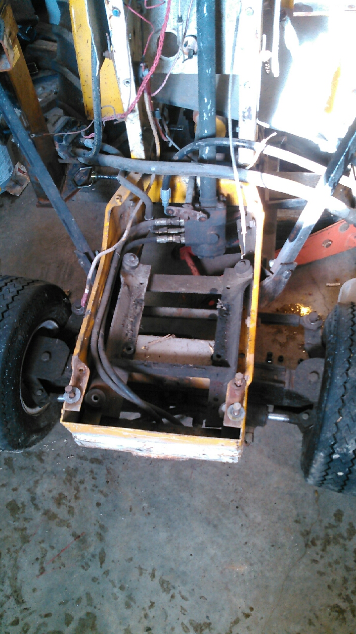 CHIT,,,thought I resized em,,,, Hey Dave,,,That is ONE STOUT Front end for sure,,,,, What pump did you use and I'm assuming it is belt drive,,,?? What are the specs on it,?? |
Posted By: desertjoe
Date Posted: 19 Dec 2016 at 12:10am
|
PIC #2  |
Posted By: BenGiBoy
Date Posted: 19 Dec 2016 at 7:39am
|
That looks sturdy!!! ------------- '39 Model B Tractors are cheaper than girls, remember that! |
Posted By: DaveKamp
Date Posted: 19 Dec 2016 at 9:29pm
|
Yeah, its strong... ------------- Ten Amendments, Ten Commandments, and one Golden Rule solve most every problem. Citrus hand-cleaner with Pumice does the rest. |
Posted By: desertjoe
Date Posted: 19 Dec 2016 at 9:35pm
|
Hey Dave,,give us some detail or Mfgr. and model # of the pump you used,,,, Belt driven,,?? |
Posted By: DaveKamp
Date Posted: 19 Dec 2016 at 10:51pm
|
Toothed-belt drive- a Carlisle Panther RPP... like Gates PolyChain... about a 2:1 ratio. The pump... I don't recall the brand, it's Italian, if I remember correctly, it's about 0.72ci per rev displacement. The unique feature is that it has an integral priority valve. Priority valve means that the output's full flow is made available to the priority port, and once that's satisified, the other port gets all the rest. I have the priority port plumbed to the steering valve, and the main work port goes to the loader valve... that way, if there's any problems, it looses loader FIRST, but idle it down, and the steering still works just fine. (I edited this because it's not a 1.2gpm pump (I confused it with one I used on a different project)... according to my notes, this one is about 0.72ci/rev. ------------- Ten Amendments, Ten Commandments, and one Golden Rule solve most every problem. Citrus hand-cleaner with Pumice does the rest. |
Posted By: DaveKamp
Date Posted: 20 Dec 2016 at 2:16am
|
Pump is rated to 1800rpm... with a 2:1 drive ratio, the engine governed at 3600 is perfect. .72ci/rev at 1800rpm comes to 1800*0.72ci=1296ci/minute or 1296/231=5.6gpm, which seems excessive considering the bucket lift and curl rams are so small, but remember that I have hydraulic steering AND... when I idle the engine down, I like the steering AND bucket to work just fine. I generally don't run the engine at much more than 3/4 throttle, because the transaxle drive ratio is rather fast. When doing delicate bucket work, I like to run it slow and gentle, and still have flow on the pump. And for what it's worth, the 12hp K-series was 'strong'... because when I rebuilt it, I planed the block and head, used a taller piston and forged rod, so there was plenty of compression. It was probably more in the 15hp range... at least, until something inside came unglued. One of these days I'll open it up for a look. ------------- Ten Amendments, Ten Commandments, and one Golden Rule solve most every problem. Citrus hand-cleaner with Pumice does the rest. |