| Author |
 Topic Search Topic Search  Topic Options Topic Options
|
Alex09(WI) 
Orange Level


Joined: 15 Mar 2012
Location: CECIL WI
Points: 1698
|
 Post Options Post Options
") Thanks(0) Thanks(0)
") Quote Quote  Reply Reply
 Topic: D17 Live Hydraulics project Topic: D17 Live Hydraulics project
Posted: 26 Sep 2022 at 9:41pm |
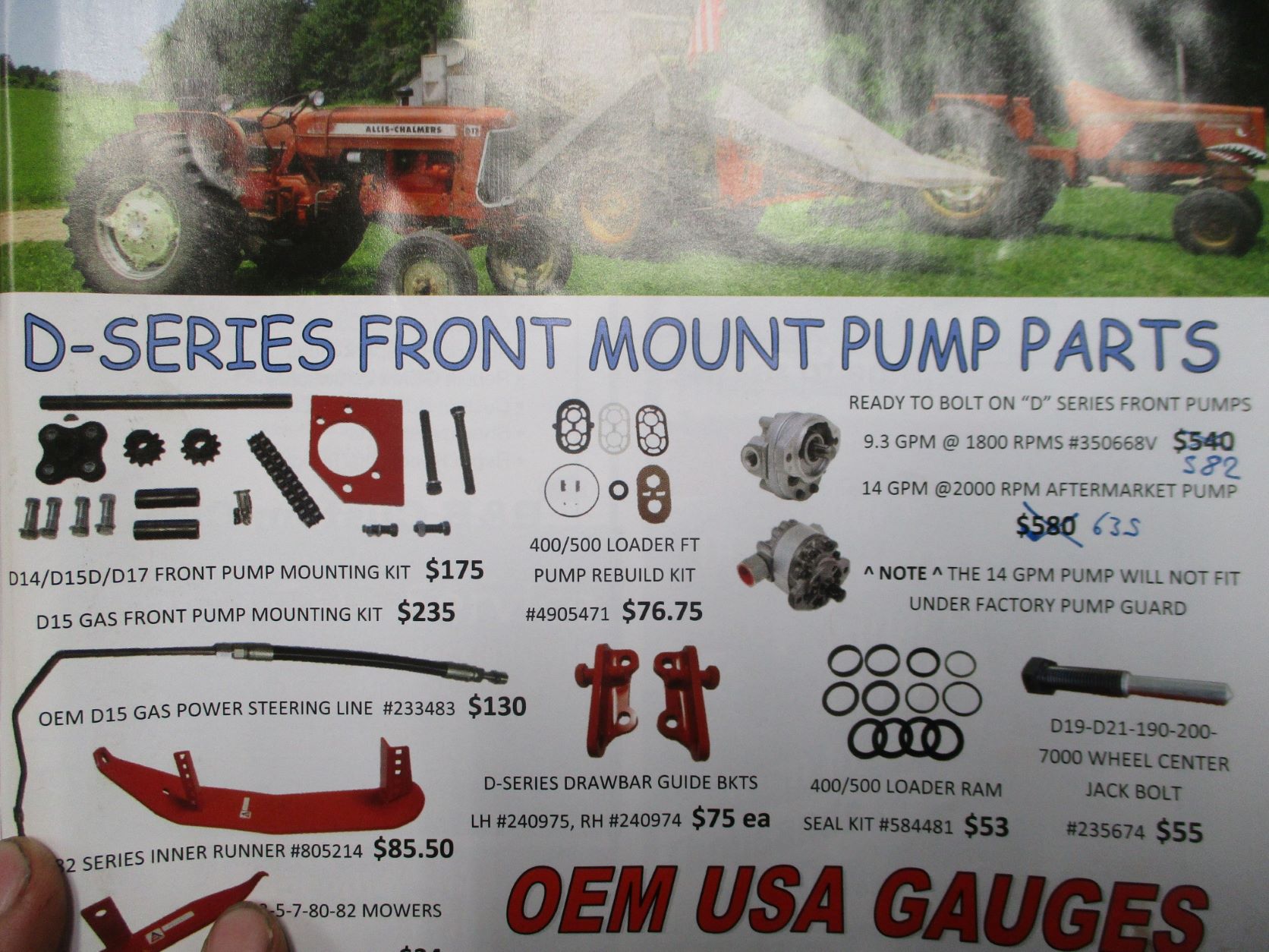
To make modernizing your tractor easier, we offer these front mounting kits for purchase. No machining required. Make sure your front pulley has provision to bolt adapter hub!
Tractors earlier than: D14 engine serial #149-11562/ tractor serial #11476 and D17 gas tractor serial #15931/diesel tractor engine #104840 DID NOT leave the factory with the front pulley that has the 4-bolt pattern for adapter hub.
|
|
www.awtractor.com
A&W TRACTOR 920-598-1287
KEEPING ALLIS-CHALMERS IN THE FIELDS THROUGH THE 21ST CENTURY
|
 |
|
Sponsored Links
|
|
|
nsula_country
Orange Level

Joined: 10 Mar 2011
Location: NW Louisiana
Points: 218
|
Post Options
Thanks(0)
Quote Reply
Posted: 25 Apr 2012 at 11:28pm |
I have a Farmall 504 diesel of 1962 vintage. Early 2nd year. It has a crank pulley that also has hand crank finger bosses. It also has a hole for a crank in the bolster! Who hand cranks a diesel? I feel they were using up old parts at the time!
CT
|
|
2014 LS P7010C, 1962 Farmall 504 Diesel (1st tractor) w/ 2008 Koyker 220 FEL, 1968 Allis Chalmers 180 Diesel, Komatsu PC38UU-2 Excavator, Various attachments for all!
|
|
DaveKamp
Orange Level Access
Joined: 12 Apr 2010
Location: LeClaire, Ia
Points: 5637
|
Post Options
Thanks(0)
Quote Reply
Posted: 17 Dec 2011 at 10:55pm |
|
Hi SC!
Cool that it all fits! if it's clearing okay, then power to 'ya!!!
I"m wondering why Steiner has it listed, but doesn't include the compatibility to AC...???
Between a barrage of business road-assignments, I've been working on my snowblade installation, so haven't made much progress on my live hydraulic setup... but I'll get back to it in a bit. Eventually, my snowblade (a 7.5' Meyer) will lose it's electric hoist/swing system, and get quick-connectors and a lift ram for using the live hydraulic system, but for now it'll be using a battery. Stay tuned!
|
|
SenseiCrusher
Silver Level

Joined: 20 Sep 2011
Points: 124
|
Post Options
Thanks(0)
Quote Reply
Posted: 15 Dec 2011 at 12:55pm |
|
Hi Dave, I have the project finished, the adapter I bought is for a 1" 10 spline not a 20 spline. The Max shaft OD at the adapter (splines) is 1.0". The adapter bolted right up to the pully. The shaft area where it goes through the bolster is 0.8 inches. The ID clear on my D17 series 1 is 1.30". It fit through with no issues of alignment at all and I can remove it with no problems!
|
|
DaveKamp
Orange Level Access
Joined: 12 Apr 2010
Location: LeClaire, Ia
Points: 5637
|
Post Options
Thanks(0)
Quote Reply
Posted: 28 Nov 2011 at 9:38am |
|
And Sensei- I looked at the Steiner ref, and it's cool that they have a coupler listed... I found it curious, however, that it didn't list it as fitting the Allis tractors... seein's how it does, in fact, bolt up.
Then I looked closer...
Your coupler is listed as being a 1" x 20 spline shaft, which is a common standard size for SAE2 and SAE3 hydraulic pumps.
I used a less-common standard 7/8 x 13 spline shaft, because it will fit down the center of the stock bolster crank-hole.
A 1" shaft won't fit my Series 1 bolster... if I remember correctly, the bolster hole was just big enough for the 7/8" shaft to fit and engage the coupler, and leave mebbie 0.060" 'play' before striking the bolster bore, and a 1" was too big to allow a proper lineup. I sure hope it'll fit yours...
Edited by DaveKamp - 28 Nov 2011 at 9:39am
|
|
DaveKamp
Orange Level Access
Joined: 12 Apr 2010
Location: LeClaire, Ia
Points: 5637
|
Post Options
Thanks(0)
Quote Reply
Posted: 27 Nov 2011 at 9:41pm |
|
JK, sorry- I went back and checked my posting... dunno why I posted 2.6gpm, SHOULD be 2.6 CUBIC INCHES per Revolution. At 1800rpm, that comes out to 20gpm.
I WOULD have gone with a vane-pump, but I frequently idle the D17 way down to 'creep' it carefully into position. My Clark IT-60 HAD a vane-pump (and closed-center hydraulics) and regularly shelled out (and seized up) vane pumps, but worst of all, when it was idled-down, it went so slow that the vanes would retract, and there'd be no lift or tilt, no steering (yikes!) and general uselessness of the machine at low speed.
My general expectation is, that no matter WHAT I run, I don't think I'll ever run an implement that needs more than 20gpm at 2000psi... and it'd probably be a ditch-mower (flail, etc) or something similar. To get that, I'll be at max goverened speed. When using a log-splitter, or the backhoe unit, I don't think I'll need more than 5-6gpm, so burbling along at 650rpm will be just fine.
|
|
SenseiCrusher
Silver Level
Joined: 20 Sep 2011
Points: 124
|
Post Options
Thanks(0)
Quote Reply
Posted: 27 Nov 2011 at 10:25am |
|
|
|
JK in Pa
Bronze Level


Joined: 12 Sep 2009
Location: Dushore, Pa.
Points: 159
|
Post Options
Thanks(0)
Quote Reply
Posted: 27 Nov 2011 at 8:58am |
|
Some nice looking machine work there, Dave. I am curious why you are using such a small pump. I installed a vane pump in my WD about Twenty years ago when I built my Backhoe. I used a 12 GPM@ 1200 RPM. Worked out to be the perfect fit. Good Luck.
|
|
DaveKamp
Orange Level Access
Joined: 12 Apr 2010
Location: LeClaire, Ia
Points: 5637
|
Post Options
Thanks(0)
Quote Reply
Posted: 27 Nov 2011 at 8:10am |
Here's the shaft. 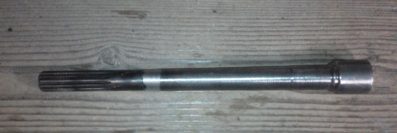 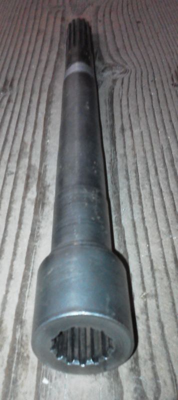 Cool illusion on the second pic- taper in the shaft, and angle makes the image look like it's wider at the top! Pretty simple assembly, really... all it does, is extend the engine's coupler from the engine, to a point in front of the front bolster. When I machined this, I did what any wise machinist would do, and that is, use the splined shaft center as the reference for runout, to make it run true. I used the unused portion of the splined shaft and couplers to MAKE it run true in the lathe, then I made cuts across the OD to yield a 'reference surface' that was concentric to the shaft centerline. This is very important, because these parts frequently aren't concentric... that coupler was clearly a couple thou out on the OD, and the splined shaft was mebbie half that. Get 'em 'phased' right, and the net runout will be very small, but phase 'em wrong, and it's alot of wobble over a foot's span. Now, it doesn't matter which way I install it, it runs dead-true. There's more than enough coupler depth to fully engage the pump's splines, and still leave plenty of room for motion. Need to leave enough slack so that things can flex a bit, even though they really shouldn't. Next, I'll make a bracket to hold the pump that 'floats' with the shaft, but restrains the shaft against torque load, and finally, allows easy removal and installation of this shaft for those times when I don't want the added mechanical load on the engine. Stay tuned!
|
|
DaveKamp
Orange Level Access
Joined: 12 Apr 2010
Location: LeClaire, Ia
Points: 5637
|
Post Options
Thanks(0)
Quote Reply
Posted: 25 Nov 2011 at 2:23pm |
|
By the way... neck surgery is well-healed, and the arm-strength is back. Really helps when holding a welding electrode. Now if I was only home a bit more often!
|
|
DaveKamp
Orange Level Access
Joined: 12 Apr 2010
Location: LeClaire, Ia
Points: 5637
|
Post Options
Thanks(0)
Quote Reply
Posted: 25 Nov 2011 at 2:18pm |
In the meantime... I found a hydraulic tank... about 18 gallons or so.
This one has baffles in it, and cleanouts... but interestingly enough,
no suction strainer... instead, it had some sort of clamp-in bulkhead
fitting that was long-gone when I got the tank. I ordered a
weld-in flange 2" NPT, and a suction strainer 2" NPT outside, and 1.5"
ID. I used a hole-saw to open up the original hole, then welded in the
flange and installed suction filter. Notice, it's located in a really
nice spot- suction line can come forward along the frame rail, into the
proper side of the pump (yes, I thought about that beforehand). I made
a bracket and tack-welded it to a removable rail (made rails for both
sides). I'm still contemplating position here. From a
convenience standpoint, this is great- I can reach all the engine
service points without removing the tank, and the tank is easily
accessable. On the back side of the tank (facing driver) is a
combination level and temperature gauge, so perfect. Problem is, it
obstructs view to the right-front wheel. I'm not row-cropping, so it
probably isn't a big deal, but I DO maneuver into areas where being able
to see that front wheel is important. I can stand up in the op
position and see the tire, just not while seated. Moving it to the rear
will make it so that anything being thrown off the front or rear tires
will land ON the tank. Moving it lower will cause it to be hit by the
tire when the axle is all the way up (on that side) and tire is turned.
I haven't found any other places that are 'better', so without going to
a different tank shape, this will probably be it... and I'll probably
be mounting an 8D battery on rails on the other side of the tractor to
match... we'll see. 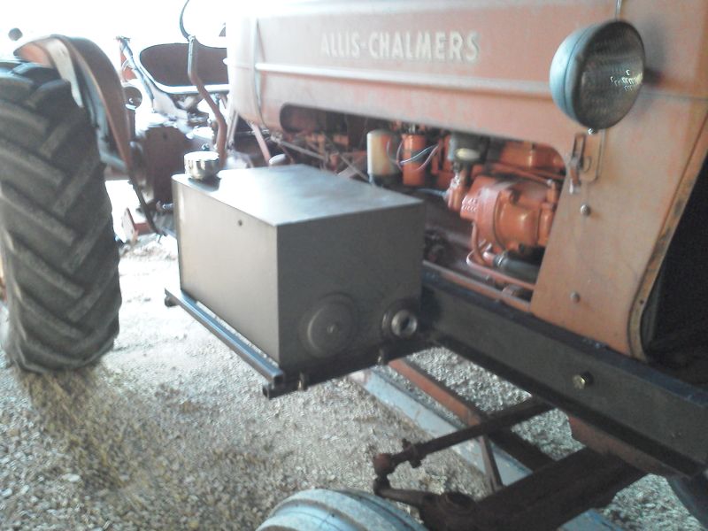
|
|
DaveKamp
Orange Level Access
Joined: 12 Apr 2010
Location: LeClaire, Ia
Points: 5637
|
Post Options
Thanks(0)
Quote Reply
Posted: 25 Nov 2011 at 1:56pm |
|
What I did, in the previous picture...
I obtained a PAIR of splined-shaft couplers, and a splined shaft to match the hydraulic pump. These are fairly standard, but apparently not standard enough for a 'stock'
shaft length long enough to make the reach from my crankshaft drive to the pump bracket up front.
So I took a piece of shaft stock, squared it up in the 4-jaw, and skim-cut one end, then I cut a segment down a bit.
Then I cut the coupler a little shorter (short enough so that it would fully engage the pump, of course), and centered it up in the 4-jaw. Gotta note here- the splined hole was NOT concentric to the OD of the coupler, so instead, I put the splined SHAFT in the chuck, adjusted it to run true, then put the COUPLER on the shaft (held it in with the live-center), and skimmed the OD to be concentric with ID. Then I cut a recess in the coupler to be about a thou SMALLER than the OD of the shaft stock. I then put the shaft stock in the freezer, warmed up the coupler, then dropped the two together. Upon cooling, they were not only very, very snug, they were dead-on true. Then I applied a fillet-weld around the outside (with a MIG), and a rosette weld on the inside (with a stick). Chipped out the sl*g and knocked the spatter away, chucked the SHAFT in the lathe, adjusted to run true, then stuck the splined shaft in, put live-center on the far end, and checked to see if it all STAYED true.
Rule is, always do all weldments FIRSt, and do machining LATER... well, sometimes 'ya can't... in which case, you always get the welding done, and leave yourself a way to CHECK out the results, and in the event something DOES get stressed out-of-true, you can always SKIM it back into a true state.
Next thing I did, was cut the splined shafting to appropriate length, and I turned it to leave about a 3/8" stub out the end 1" or so. I cut the OTHER piece to proper length, and bored a similiar hole, about a thou too small, and shrunk, then welded the two together, then skimmed the whole works down to make a complete unit. Don't see the photo here, so I'll post it later.
|
|
DaveKamp
Orange Level Access
Joined: 12 Apr 2010
Location: LeClaire, Ia
Points: 5637
|
Post Options
Thanks(0)
Quote Reply
Posted: 25 Nov 2011 at 11:31am |
Yeah, it's been a while, but I HAVE been nippin' away at this project. I got the shaft made... here's what it looked like halfway-done... 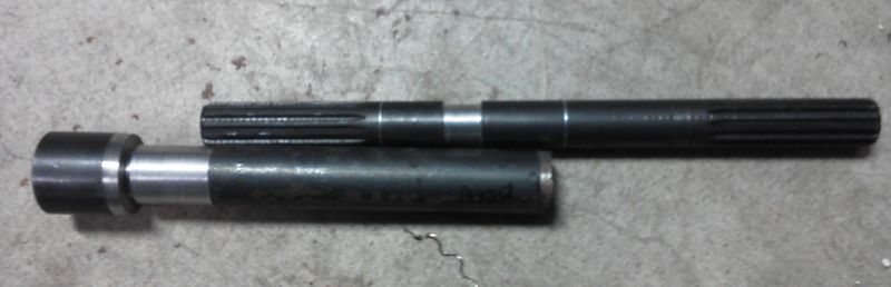
|
|
DaveKamp
Orange Level Access
Joined: 12 Apr 2010
Location: LeClaire, Ia
Points: 5637
|
Post Options
Thanks(0)
Quote Reply
Posted: 17 May 2011 at 2:48pm |
|
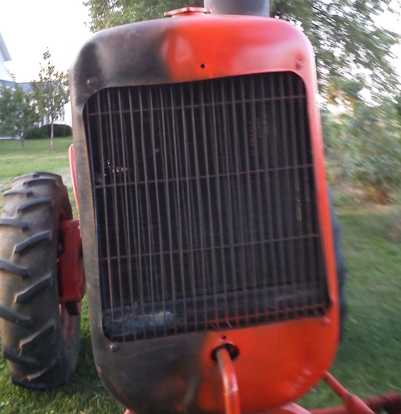
Okay, well, things seem to happen this way... but when I was in there changing everything, I took the time to flush out the engine, change the thermostat (stuck tight!), and rinse out the radiator... and it was pretty yukky inside.
After getting the coupler finished, I put it all back together, filled it with water, and run it a bit (to check for leaks). All fine, so I drained and flushed it a little more... drained again... then refilled with a 60/40 mix of ethylene glycol and water.
And the radiator sprung a leak.
ARGH!!!!
Well, it was fixable. Apparently there was just-enough-crud in that one tube to keep it from leaking. I was extra dilligent to flush it out, 'cause I thought I saw a spot down there a while back that was weeping... well, it was. Looks like a piece of something got in there once and nicked a tube... radiator shop boiled it out, fixed the leak, and now she's back together and working. Next step: front pump mount, but before I do that, gotta take a little time-out to fix a neighbor's post-hole auger, drill me a few holes in the yard, pour a little concrete, and build a few other things... gonna do it while I have good sunshine, and come back to this one when we're gettin' rain. Stay tuned!
|
|
MACK
Orange Level
Joined: 17 Nov 2009
Points: 7664
|
Post Options
Thanks(0)
Quote Reply
Posted: 15 May 2011 at 10:08pm |
|
Easy way to make a front drive for D17 is to make a shaft same size as crankshaft, mount front pulley on shaft anm make it all on the lathe. Made mine from a D17 steering shaft and couppler. Couppler and end of steering shaft are hardened and will last almost for ever. Mine has been on there for 20 years, had it out last winter to rebuild engine. could not see any wear. MACK
|
|
DaveKamp
Orange Level Access
Joined: 12 Apr 2010
Location: LeClaire, Ia
Points: 5637
|
Post Options
Thanks(0)
Quote Reply
Posted: 15 May 2011 at 9:06pm |
|
Yep, and they tend not to break apart as readily as the tabs of a LoveJoy when the rubber isolator spits out.
Hmmm... screamin' Jimmy in a D8? I owned a D8 for about 20 minutes once... it's a long, tiring story, but the short of it, was that it had been sitting for 25 years, had a tree growin' through it... but if I could get it started, it was mine. Of course, I got it started... and a neighboring farmer showed up, reminded the owner that he's offered $3500 for it if he could prove it'd start and run...
That was a fun day. Never did DRIVE it, but the other farmer did... didn't even worry about the tree... 10" diameter, growin' between the blade and a track... went right over it, busted it off like a twig. Cool machine! Good thing I didn't try to keep it... I didn't have anyplace to PUT it then...
Doc didn't prescribe any PT, but I'm a closet kinesiologist, Mom was a PT, then an OT, and I know my anatomy and physiology pretty well. I've been doing full ROM, stretching and light weight routines (limited to 30lbs), and have been getting better, but 2 weeks of having the RH ulnar, radial, and medial nerve cluster clamped between C5 and C6 really put a hurt on my right arm. I'm doing really well in most positions, but some (you mentioned overhead) are really tough... and the only way I've been finding out what positions are weakest... is by seeing really crappy results... holding wrenches, welding stinger... painting... gettin' better, though. Should'a welded that in a rotary table with the MIG...
|
|
E7018
Bronze Level
Joined: 07 Dec 2009
Points: 167
|
Post Options
Thanks(0)
Quote Reply
Posted: 15 May 2011 at 6:26pm |
|
That first drive is on my D8 Cat with the 8V71Turbo. Some day, you will have to get by here and drive it in a couple circles.
The welding is a bugger with a bad arm. Sometimes, I have to do way out of position welding with my left hand. Way up on something high. I can get it but not well.
My daughter is a physical therapist, do your exercises, they work.
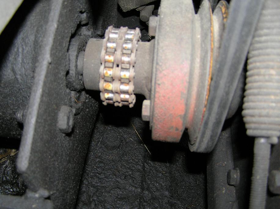
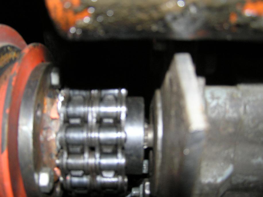
There isn't room to use a chain coupling on a D17. Even getting the connector link in can be a challenge. Worse than it looks. I try to keep a roll of 60 2 cottered chain around to make couplings. Those couplings seem to stand more misalignment and angle than Lovejoy couplings.
|
|
DaveKamp
Orange Level Access
Joined: 12 Apr 2010
Location: LeClaire, Ia
Points: 5637
|
Post Options
Thanks(0)
Quote Reply
Posted: 15 May 2011 at 6:02pm |
|
Yep, in-situ machining on the running engine assures that you'll be concentric... and I've done that trick more than once.
Although they're frequently used outside of the range, chain couplers are frequently recommended for use only under 1000rpm or so. Nice thing is that they have a little compliance, easy to make (as long as you have some double roller chain and two sprockets) but they do take up precious space in comparison to a splined-sleeve.
Gawd... ain't that weld disgusting? I can't wait to get my right arm strength back... next X-ray appointment is the 23rd...
|
|
E7018
Bronze Level
Joined: 07 Dec 2009
Points: 167
|
Post Options
Thanks(0)
Quote Reply
Posted: 15 May 2011 at 4:11pm |
|
|
|
DaveKamp
Orange Level Access
Joined: 12 Apr 2010
Location: LeClaire, Ia
Points: 5637
|
Post Options
Thanks(0)
Quote Reply
Posted: 15 May 2011 at 10:26am |
|
Cool idea, Jack!
One of the things I wanted to accomplish here, was make the coupler so that a guy wouldn't hafta take the radiator and front bolster off to install or change it... and while I installed this with that all off, there is clearance aplenty to do so. The only thing a guy MIGHT run into, is if the sheave bolt-holes were full of crud... he'd have a cussing-circus of cleaning 'em out, but it can be done with patience.
Obviously, this coupler layout won't work for an early-style sheave, and I'll dig into that later, but for now, I gotta get this system goin' and get the backhoe mounted and operational.
The splines DO tolerate a little malignment... albeit with spline wear. The more-true it runs, the less the splines 'scrub' on the couplers, hence, the longer everything lasts.
And there's really two aspects of alignment to focus on... first, making sure that the engine-side coupler runs true to the axis of the crankshaft... you want the centerline of the splined-coupler to be dead true to the crankshaft's axis... you don't want it to be too high, or too low... and you don't want it pointed out at an angle... you want it to be centered and concentric, so that when it spins, you can't see any sort of wobble, even if there's a 1' long shaft sticking out of it. The second aspect, is having the pump lined up with that same axis. The second is fairly easy to obtain once the first has been established... the splined shaft points the way... I'll be getting to that piece next.
|
|
Pat the Plumber CIL
Orange Level

Joined: 11 Sep 2009
Location: Springfield,Il
Points: 4675
|
Post Options
Thanks(0)
Quote Reply
Posted: 15 May 2011 at 9:49am |
|
Thanks for posting pics Dave.Very informative and interesting.
|
|
You only need to know 3 things to be a plumber;Crap rolls down hill,Hot is on the left and Don't bite your fingernails
1964 D-17 SIV 3 Pt.WF,1964 D-15 Ser II 3pt.WF ,1960 D-17 SI NF,1956 WD 45 WF.
|
|
Jack(Ky)
Orange Level
Joined: 12 Sep 2009
Location: Ky
Points: 1151
|
Post Options
Thanks(0)
Quote Reply
Posted: 15 May 2011 at 7:38am |
|
I made one like this for Herb (Ga) a couple years ago. I used the 7/8" splined coupling and welded it to a plate and trued it up good on the lathe. The splines seem to have plenty of room to allow for misalignment. His loader had the pump mounted to it so I made the shaft with splines so he could just unbolt the loader and back out of it and the shaft would slip out of the bolster and stay with the pump.JP
|
|
DaveKamp
Orange Level Access
Joined: 12 Apr 2010
Location: LeClaire, Ia
Points: 5637
|
Post Options
Thanks(0)
Quote Reply
Posted: 14 May 2011 at 11:19pm |
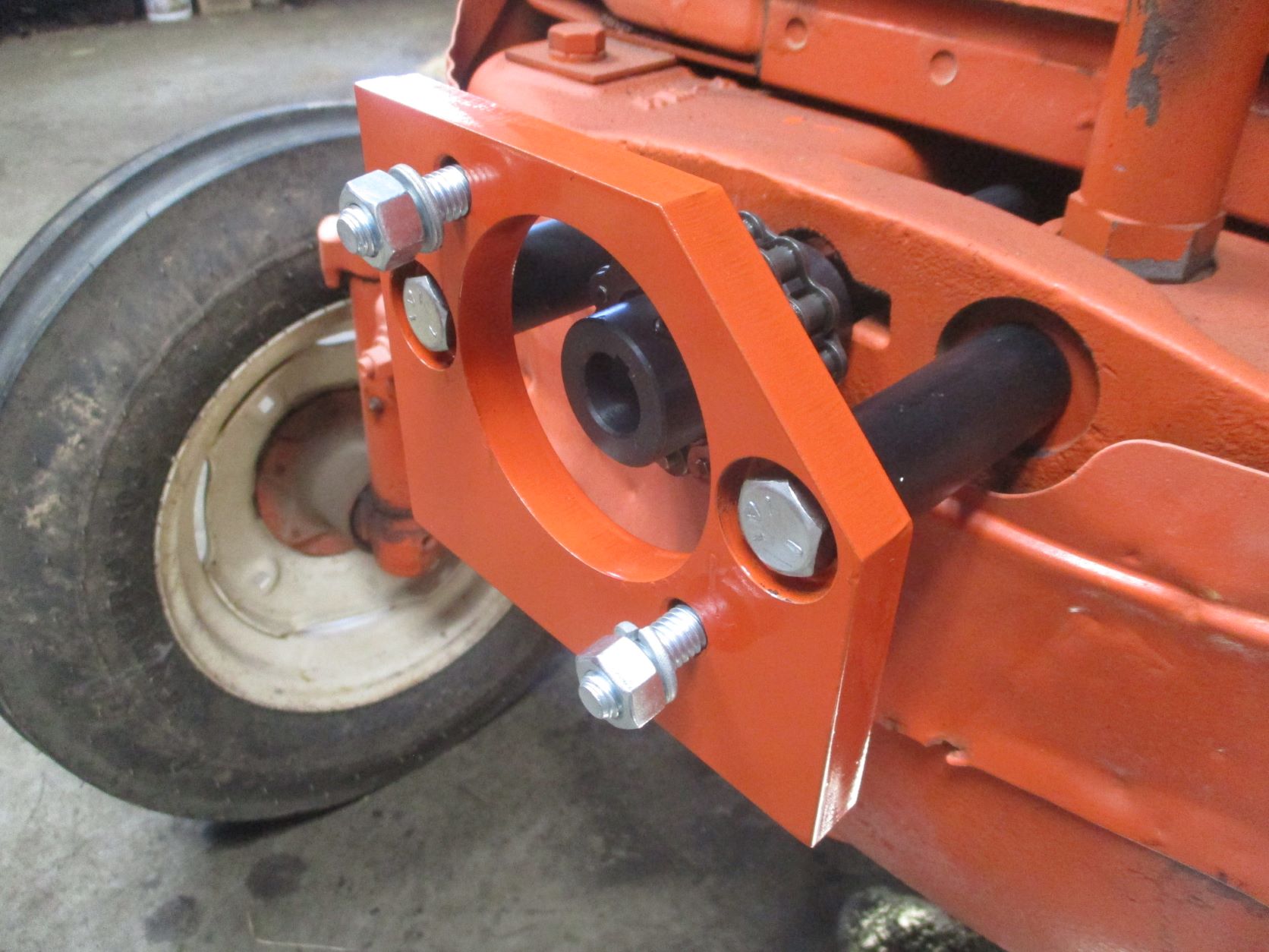
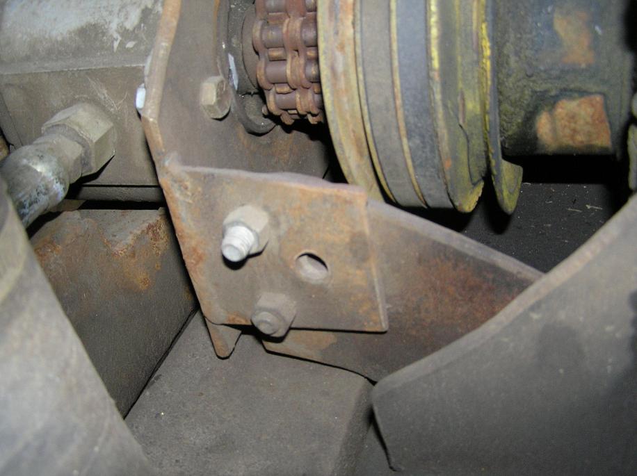
Next, is to cut some studs suitable for this setup...  I cut some Grade 5 full-thread bolts to appropriate length... 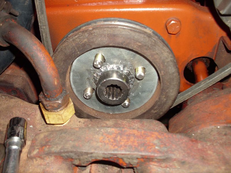 Test fitted everything... then yanked it back out, hit it with some orange paint... then slid back in (and got a grease-smudge on the new paint!) 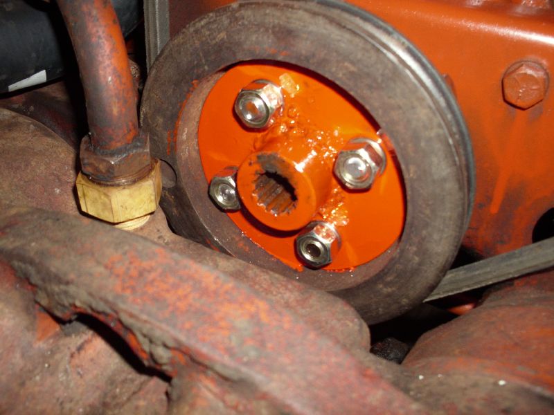 Then I fired it up, and looked at everything spin... and it spun nice and true!!! Reinstalled the radiator shell, 'cause I need to move some stuff around tomorrow, and make a wire-installation plow... then make the front pump mount bracket system...
|
|
DaveKamp
Orange Level Access
Joined: 12 Apr 2010
Location: LeClaire, Ia
Points: 5637
|
Post Options
Thanks(0)
Quote Reply
Posted: 14 May 2011 at 11:13pm |
Okay, so I had to take a couple of weeks off of shop-time to drive down to Tennessee to install some machines... then race back and bury my grandmother... and things are now getting back to normal, so I spent about half of today in the workshop. So I welded the turned coupler section into the piece of scrap plate. Welding quality, from a cosmetic point of view, was miserable... humidity has been really high, and that box of E7018 soaked it up pretty good... didn't help that my mask needs a new glass, and my right arm is still pretty lame from neck surgery a few weeks ago, but it IS improving: 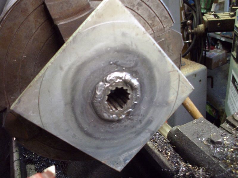 Now, important to note that you always do weldments first, followed by machine work. This way, thermal distortion that occurs, can be corrected by making appropriate skim cuts in machining process. The only exception here, is when you need to use machine tools to FIT UP the parts being welded... which is exactly what I did. Next thing to note- I clamped these pieces together, and tack-welded the BACK side together first... then I allowed it to cool, and checked to make sure that it was actually welded in flush. Typically, when welding, the weld will either PUSH or PULL the parts. In this case, I welded the back, knowing that my tack-welds will PUSH the components together tighter, rather than pull them apart (and not spin true). After tacking from the rear, I welded the front (in 4 beads... two opposites, cool, then two opposites), and then put a bead around the back. Chucked it in the lathe, cut the excess off (to make a round plate, and skimmed the back (where it'll bolt to the sheave) to be totally flat. I used a piece of carefully fitted rod against a dial indicator to make sure that the HUB centerline was concentric to the spindle axis, so that the coupler face would make the splined shaft run true. 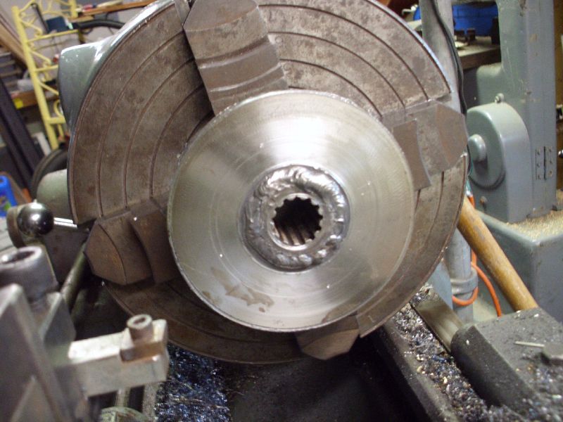 Then I located and drilled holes appropriate for studs into the front sheave... 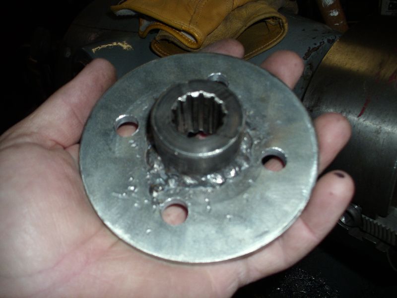 Yep, that's a shameful-lookin' bead, but can't turn back now or re-weld, it'll destroy the work. Plenty strong, so not worried about failure. 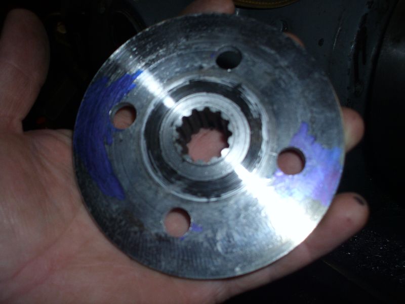 Back side shows the flush/smooth mounting surface, as well as some blue ink left over from locating holes for a-drillin'. Typically, a machinist will use blue dye to make scribe marks very easy to see... but I find that in most cases, all I need is a blue Sharpie... ink the area a little, and hit it with the scribe...
|
|
DaveKamp
Orange Level Access
Joined: 12 Apr 2010
Location: LeClaire, Ia
Points: 5637
|
Post Options
Thanks(0)
Quote Reply
Posted: 01 May 2011 at 3:53pm |
Busy with lots of things today, but I got this far... Found a perfect-sized piece of scrap... had a hole in the middle, so I roughly centered it... 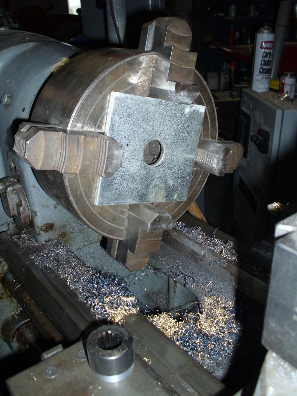 There's the coupler piece down on the apron... So I opened up the hole to proper diameter, and cut a flat area in the face to make the coupler's shaft axis WANT to be perpendicular to the plate... 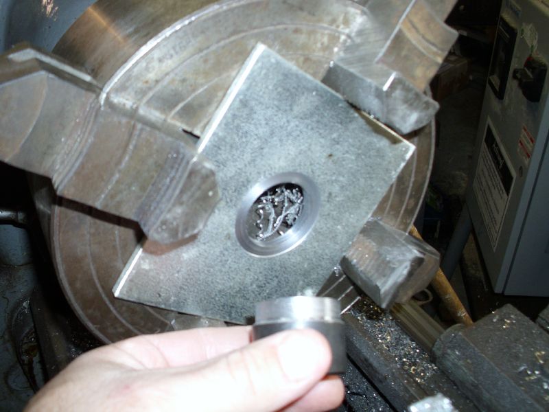 And here it is, installed in plate. 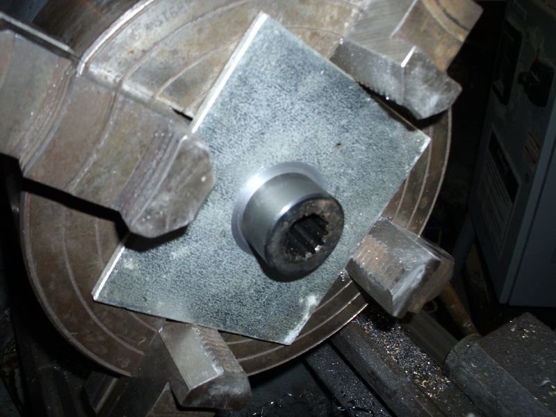 Next, I gotta weld it in. When making precision parts, one often times has to machine parts, then weld them together. Best precision is attained by doing all welding FIRST, and all machining LAST... because welding always results in some type of distortion. IN this case, I had to do first-operation... Fitting up parts that will be welded. Once welded, I'll chuck it back in the lathe, make sure it registers on-center, and then do the final machine-work. This way, I can negate any distortion of the plate or hub alignment by making a skim-cut to correct. I'll also assure that the coupler is round, centered, balanced, and that the hole pattern is properly located.
|
|
DaveKamp
Orange Level Access
Joined: 12 Apr 2010
Location: LeClaire, Ia
Points: 5637
|
Post Options
Thanks(0)
Quote Reply
Posted: 01 May 2011 at 10:38am |
|
As would I - Allis was incredibly adept at industrial engineering- process, workholding, fixtures and tooling. Making farm equipment was really only a SMALL part of their business, but the key element of all divisions was machine and foundrywork.
|
|
DrAllis
Orange Level Access
Joined: 12 Sep 2009
Points: 19473
|
Post Options
Thanks(0)
Quote Reply
Posted: 01 May 2011 at 7:33am |
|
I'd be very skeptical that the crank pulley itself may not run true.
|
|
DaveKamp
Orange Level Access
Joined: 12 Apr 2010
Location: LeClaire, Ia
Points: 5637
|
Post Options
Thanks(0)
Quote Reply
Posted: 30 Apr 2011 at 11:32pm |
|
I'll be investigating the hole runout and concentricity thoroughly before committing to it, but I'll make the coupler so that it is dead true, AND if there's a problem with the sheave's bolt heights, I'll come up with a sure way to correct for it. Having splines in the middle of the sheave is an excellent idea, if they would've incorporated it at the factory. The whole idea here, is to establish a very simple, robust, and easy to install drive system, without need to tear the radiator and front bolster out. I've already had to pull the bolster to get the 2-bolt sheave out, and the 4-bolt in. I'm building this setup with the 4-bolt sheave, but eventually I'll be exploring a coupling system for the 2-bolt sheave.
Runout at all locations should be expected, and taken into account, however, the best way to resolve it, is to understand how the original sheaves were manufactured. The casting was roughed-in, and then cut, and would've been cut so that all surfaces requiring concentricity, would be cut in a series of operations that never required a change of workholding... example: The sheave bore, the sheave seal OD, the V-belt path and OD, all cut without removing the workpiece from the lathe. This obviously doesn't assure that the workpiece was properly registered to begin with, but if I were the factory machinist, I would have made the workholding fixture so that when installed, the workpiece registered with very predictable results every time.
NO set screws- set screws WILL force the shaft to run off-axis, and will not allow it to compensate for relative motion. I'll have just enough compliance in the pump mounting bracket to prevent binding, but little more.
|
|
Nathan (SD)
Orange Level
Joined: 11 Sep 2009
Location: Day County SD
Points: 1241
|
Post Options
Thanks(0)
Quote Reply
Posted: 30 Apr 2011 at 1:18pm |
I don't think the bolt holes in the pulley are machined flat. If you bolt the plate in the pulley and then weld the hub to the plate, you will have to make sure the plate goes into the exact same spot any time you disassemble it. A 1 in 4 chance to be wrong.
If the 4 holes ARE machined flat then none of this matters and the plate will be fine.
|
|
BobHnwO
Orange Level

Joined: 16 Sep 2009
Location: Jenera Ohio
Points: 693
|
Post Options
Thanks(0)
Quote Reply
Posted: 30 Apr 2011 at 12:51pm |
|
I would weld the coupler to a plate then bolt it to the crank pulley.
|
|
Why do today what you can put off til tomorrow.
|
|


 Dave, I have made several of those couplings by making the plate with the bolt holes for the crank pulley and the center hole. Then, fasten it to the crank, mark the position, so it always goes back on the same. Then, weld a stick of threaded bar to something on the tractor so I can fasten the die grinder to the threaded bar and have the cutter in the center hole. Start the engine at idle. With the die grinder "on", move the cutter to the edge of the hole. Grind til it is a perfect circle. Then, make a short piece of shaft in the lathe to just fit in the hole in the plate on one end and the sprocket hub on the other end. Take plate off and put shaft in for welding. After welding, discard piece of shaft. I use a double roller chain for couplings.