175 Brake part
Printed From: Unofficial Allis
Category: Allis Chalmers
Forum Name: Farm Equipment
Forum Description: everything about Allis-Chalmers farm equipment
URL: https://www.allischalmers.com/forum/forum_posts.asp?TID=180770
Printed Date: 15 Apr 2026 at 1:21am
Software Version: Web Wiz Forums 11.10 - http://www.webwizforums.com
Topic: 175 Brake part
Posted By: TomYaz
Subject: 175 Brake part
Date Posted: 26 May 2021 at 11:58am
|
Hi all, Anyone tell me the part number of the "X"?? Cant seem to find the part in my 175 parts catalog....also, helluva time getting the circled pin out. Seems frozen good.... 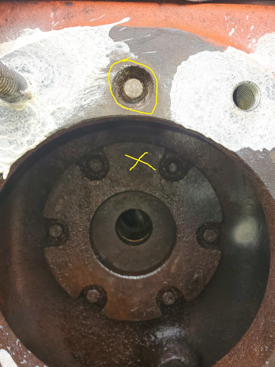 ------------- If its not an All-Crop, it all crap! |
Replies:
Posted By: Joe(TX)
Date Posted: 26 May 2021 at 6:45pm
|
Looks like the differential carrier. I had to make a puller for a small slide hammer. One end has 3/8 threads which are not labeled on the drawing.  ------------- 1970 190XT, 1973 200, 1962 D-19 Diesel, 1979 7010, 1957 WD45, 1950 WD, 1961 D17, Speed Patrol, D14, All crop 66 big bin, 180 diesel, 1970 170 diesel, FP80 forklift. Gleaner A |
Posted By: TomYaz
Date Posted: 26 May 2021 at 6:52pm
|
Thats neat Joe! Know someone who can make me one? $ for your trouble of course! I dont understand 100% how these brakes work...so you got these bands similar to the wd45 and D17 that mount on this pin,,,they provide braking contact on the drum...but If i am understanding right the drum sides it self are a braking surface too?? Is this part I want to know about part of that?? ------------- If its not an All-Crop, it all crap! |
Posted By: Joe(TX)
Date Posted: 26 May 2021 at 7:05pm
|
The band clamps on the drum. the drum has balls that spread the friction plates which press on the the friction discs on both side. friction plates are on the differential housing and the axle housing. ------------- 1970 190XT, 1973 200, 1962 D-19 Diesel, 1979 7010, 1957 WD45, 1950 WD, 1961 D17, Speed Patrol, D14, All crop 66 big bin, 180 diesel, 1970 170 diesel, FP80 forklift. Gleaner A |
Posted By: TomYaz
Date Posted: 26 May 2021 at 7:12pm
Yeah I found this video... https://www.youtube.com/watch?v=FBChZvd725U" rel="nofollow - https://www.youtube.com/watch?v=FBChZvd725U this part is a braking surface...but why the heck isnt it in the parts catalog??? Anyhoo,,,about that tool you made.....how can I get me one? ------------- If its not an All-Crop, it all crap! |
") Joe(TX) wrote:
Joe(TX) wrote:Posted By: Lynn Marshall
Date Posted: 26 May 2021 at 7:53pm
| Part# 70237183. It may or may not be available and the cost could be high. You could probably have your old one surfaced if that is the problem. |
Posted By: TomYaz
Date Posted: 26 May 2021 at 8:02pm
|
Thanks! ------------- If its not an All-Crop, it all crap! |
Posted By: MACK
Date Posted: 26 May 2021 at 9:13pm
| you can machine it down to bolt heads. Just add shims to axel side ware surface. MACK |
Posted By: DSeries4
Date Posted: 26 May 2021 at 9:22pm
|
After you put the brake assembly back in the housing and put the axle on, you will have to check clearance between the brake disc and the bearing carrier. You may need to add shims to get proper clearance. The tolerance in the service manual - 33 to 88 thou rings a bell but I do not have it in front of me. ------------- '49 G, '54 WD45, '55 CA, '56 WD45D, '57 WD45, '58 D14, '59 D14, '60 D14, '63 D15D, '66 D15II, '66 D21II, '67 D17IV, '67 D17IVD, '67 190XTD, '73 620, '76 185, '77 175, '84 8030, '85 6080 |
Posted By: TomYaz
Date Posted: 27 May 2021 at 7:23am
I got the AC 175 service manual but there is nothing about brakes. Is it in the I&T? So I dont get confused as I easliy do, can you tell me below what parts you are talking about? 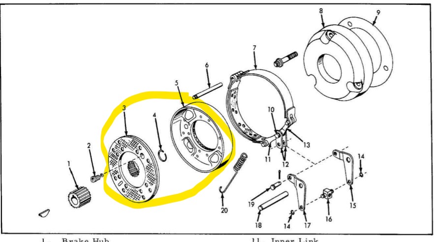 ------------- If its not an All-Crop, it all crap! |
Posted By: MACK
Date Posted: 27 May 2021 at 7:52am
| Resurface #8 and shims are #9. Measure between #5 and 8. MACK |
Posted By: TomYaz
Date Posted: 27 May 2021 at 7:58am
Ok thanks...but part 5/3 slides freely off part 1....At least thats what it looks like as I am looking at it with whole thing taken off the tractor.. What keeps 5/3 in place?
------------- If its not an All-Crop, it all crap! |
Posted By: TomYaz
Date Posted: 27 May 2021 at 7:59am
Lemme guess...the snap ring! ------------- If its not an All-Crop, it all crap! |
Posted By: critter
Date Posted: 27 May 2021 at 10:34am
| Joe is there a bolt in that puller to pinch it closed on the dowel? |
Posted By: DanWi
Date Posted: 27 May 2021 at 12:00pm
| 3 and 5 have to float that is what expands to apply the brake the bands only actuate that part to push apart. You brake against no 8 and something on the side of 3. Your clearance would be with 3 and 5 together not spread apart and between 8 and the housing or cover on the other side. Not familiar with the 170/175 but the 190 just has a cover |
Posted By: JC-WI
Date Posted: 27 May 2021 at 1:17pm
|
Tom, when I helped a friend get his 175 back to moving, he was short on dollars, thus the fix was as cheap as possible. We removed the wheel, and then the rear axle. Then made several measurements... some using a straight edge off of the mating surface of the axle and housing to surfaces. Measured the old brake assembly after putting new springs in (his had the #2 springs broke). Found the dimensions (2.423") of a new #8 friction plate. Had a machinist resurface the friction plate face and had a plate made to take the place of many shims. That brought the tolerances back to what was needed to take the slop out of all the wear. Worked good until he sold the tractor. Dimension between friction plates is suppose to be 2.034 - 2.044" . Had a gauge made with those two dimensions, sorta a go and no go gauge, if the narrow side didn't slip in, it was to narrow. and if the wide side slipped in, the area was to wide. Used it only once since it was made. ------------- He who says there is no evil has already deceived himself The truth is the truth, sugar coated or not. Trawler II says, "Remember that." |
Posted By: TomYaz
Date Posted: 27 May 2021 at 2:01pm
Being a computer programmer I am very anal here.... "Dimension between friction plates is suppose to be 2.034 - 2.044" - you mean between parts 5/3 and 8 with 5/3 being closed? Based on the other comment, there is a gap between the other side of 8 and the pictured part I posted? How the heck do you measure that gap?? ------------- If its not an All-Crop, it all crap! |
Posted By: Gatz in NE
Date Posted: 27 May 2021 at 7:04pm
|
The dimension given is shown in 2nd pic This is from an I&T manual for a D17s4 (and s3 if I'm not mistaken) You won't find this in an AC repair manual. I think they used this basic design in the 175 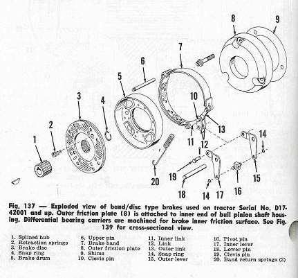 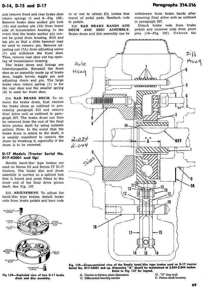  BTW, Tom, I have made an extraction tool like Joe's to get that *@!*$#* pin out. I'll look to see if I had made an extra if you're interested. |
Posted By: Joe(TX)
Date Posted: 28 May 2021 at 1:46am
I made one like the earlier posted drawing Joe ------------- 1970 190XT, 1973 200, 1962 D-19 Diesel, 1979 7010, 1957 WD45, 1950 WD, 1961 D17, Speed Patrol, D14, All crop 66 big bin, 180 diesel, 1970 170 diesel, FP80 forklift. Gleaner A |
Posted By: DrAllis
Date Posted: 28 May 2021 at 6:33am
| I assemble everything with new linings. You reach down thru the top hole and measure your disc lining clearance with a feeler gauge. One must assume the shim stack was pretty close to begin with. If you machine any part, you add that amount to the shim stack. I shoot for no less than .020" and no more than .030" with new disc linings. Suit yourself. You can assemble it and measure the distance with some sort of measuring tool, then take it back apart to correct things, or assemble it with real parts, measure and maybe be done the first time. Either way, you assemble and measure and correct if needed. |