WD45 rebuild progress
Printed From: Unofficial Allis
Category: Allis Chalmers
Forum Name: Farm Equipment
Forum Description: everything about Allis-Chalmers farm equipment
URL: https://www.allischalmers.com/forum/forum_posts.asp?TID=126761
Printed Date: 31 Mar 2026 at 8:21pm
Software Version: Web Wiz Forums 11.10 - http://www.webwizforums.com
Topic: WD45 rebuild progress
Posted By: Allis dave
Subject: WD45 rebuild progress
Date Posted: 04 Aug 2016 at 8:18am
|
I took my WD45 226 head off last Winter to fix a leaking head gasket and found some scoring on the sleeves and pistons. I decided it was time for a rebuild to help the 45 last the rest of my lifetime. There was a lot of junk in the oil pan, so I decided to follow Doc's and a few other member's tips to convert to a D17 full flow oiling system. I'll start a separate topic for that soon. Hopefully some of you will enjoy watching my progress. Most of the work has already been done and I'm just now getting time to post. I'd be happy to hear anyone's comments or lessons learned. Sleeve Installation I used a wire wheel on a die grinder to clean up the top and bottom webs and the counters bores. Then I wiped them down several times with a rag and break clean until clean. I also scraped the counter bores good with a razor. http://s1359.photobucket.com/user/dmckinney45/media/WD45%20Rebuild/Counterbore_zpsbnjwyhey.jpg.html" rel="nofollow">  I test fitted the sleeves with no orings to make sure the fit well and would rotate bore. I even marked the counter bores with a marker and then spun the sleeve to make sure I had good contact everywhere Installing the orings on the sleeves, I carefully rolled them on trying to make sure not to twist them at all. I pulled them out of the groove slightly with a pick and went around with the pick a few times. Then I followed the small forming lines on the orings to double check there where no twists. I Found an old bottle of John Deere lubricating soap. Lubed the orings, top and bottom webs and slid them in. With a little effort they seated in by hand. http://s1359.photobucket.com/user/dmckinney45/media/WD45%20Rebuild/Oring%20lube_zpsy53vhok6.jpg.html" rel="nofollow">  I clamped down the sleeves good to the block some bolts and doubled up washers. http://s1359.photobucket.com/user/dmckinney45/media/WD45%20Rebuild/Sleeves_zpswezger8e.jpg.html" rel="nofollow">  I actually did this whole process twice. I started with overbore D17 piston set, and later found a 175 8.25:1 compression motor kit. So I popped the sleeves and installed the new 4" sleeves. Funny thing was the 4 1/8" overbore sleeves had to be drawn down with the bolts to seat. The 4" sleeves went in by hand with some effort. I only used regular dish soap on the 4 1/8" sleeves because I didn't find the JD stuff yet. I'll chalk it up to the 4" orings compressing better and the JD soap being good stuff  Another interesting note was that the 4 1/8" sleeve flanges were .002 thicker than the M&W sleeves I removed and the 4" sleeves I installed last. I had a little more standout with the overbore sleeves than I really wanted, .003-.007. Now with the 4" sleeves I'm a .0015 - .005 measuring with a straight edge and feeler gauge |
Replies:
Posted By: Allis dave
Date Posted: 04 Aug 2016 at 8:53am
|
Crank installation and main bearing shimming Crank was ground to .020 under. The old Clevite bearings were stamped 10 in 1963. Guess that's when Someone put M&W's in this thing. I was originally going to have the block line bored to do away with shims, but after getting a $400 quote and some shimming advice from some forum members I decided to save my money and shim the motor. The machine shop checked the line bore and said it was good and measured to make sure I had no stretched caps or other problems. I cleaned up the bore and caps with a clean rag and break clean to make sure no material got under the bearings. With new bearings and a freshly ground crank, I had .010 of shims and the 3 bearings had clearances of .004, .004, and .003. The shim pack I got was just one solid .010. I made cut new shims from some shim stock at work shimmed .008, .008, and .009. When done the clearance measured .003, .002, and .003. So I'm happy I torqued down each bearing and measured with a plastigauge. Clearance was .004, .004, and .003. That probably would've been ok, but I really didn't want to start a fresh motor out with .004 Unfortunately, the shim pack I got was only 1 solid .010 shim. I cut new shims from some shim stock at work and shimmed .008, .008, and .009. When done the clearance measured .003, .002, and .003. So I'm happy. Lubed up the bearings and journals with Sealed Power Assembly Lube and torqued down the mains. http://s1359.photobucket.com/user/dmckinney45/media/WD45%20Rebuild/Plastigauge_zpsepfrkekr.jpg.html" rel="nofollow">  From part of Doc's full flow conversion idea, I had a small groove ground into the crank mains to help the rod bearing get oil for the full 360 rotation. The grooves were a little smaller than I wanted, but the machinist said his tool would start chattering with he did much more and was afraid of causing more harm than good. Unfortunately, this is the only picture I took of the crank journals and even it was unintentional. http://s1359.photobucket.com/user/dmckinney45/media/WD45%20Rebuild/Rear%20main%20journal_zpsprfeicbg.jpg.html" rel="nofollow">  Rear Main Seal After watching Don's video a few times, I was ready for the rear main seal. http://www.allischalmers.com/forum/forum_topics.asp?FID=18&title=farm-equipment-knowledge-base" rel="nofollow - http://www.allischalmers.com/forum/forum_topics.asp?FID=18&title=farm-equipment-knowledge-base I sanded down the upper rear main seal carrier by placing a piece of sand paper on a flat granite stone and rubbing the carrier against the sandpaper. It was pretty out of flat. I worked the main seals into their grooves after putting a few dabs of #2 permatex in for glue. I painted on some #3 permatex on the upper carrier and block to make a gasket and bolted it on. I later found that FelPro actually still makes that gasket, if you really want an actual gasket. part # FPG BS40010 I fitted the correct (smallest) F gasket around the lower main seal. I actually had to compress the seal a little with needle nosed pliers to fit the F gasket around it. I painted on a dab of #3 permatex over the F gasket for good measure and torqued down the mains. Crank end play is non-existent at this point, so good deal. http://s1359.photobucket.com/user/dmckinney45/media/WD45%20Rebuild/Rear%20main_zpstthbbvi2.jpg.html" rel="nofollow"> 
|
Posted By: IBWD MIke
Date Posted: 04 Aug 2016 at 9:04am
| Great documentation! When I did the engine for my 45 I spent a lot of time making shims and measuring clearance. |
Posted By: 79fordblake
Date Posted: 04 Aug 2016 at 4:50pm
| Great post. I'm still buying parts. I'm taking head to machine shop in morning to be completly rebuilt. Then I'll have block work done. Still need to get the timing cover renewed where the throttle shafts go and probably sending cam off to be done. |
Posted By: Don(MO)
Date Posted: 04 Aug 2016 at 8:35pm
|
Dave it looks like you are going at it the right way. Here's how clean I like to get a engine before installing new parts. I like to clean all the bolts, holes and studs top, bottom front, back, little or big.lol If you look at the lower sleeve sealing part of this block of Mike's D17 you can just make-out the lower sleeves installed for the o-ring to seal leak free again. Did I say how clean I like to have a engine when I start building it? Yes they have a word for me.lol 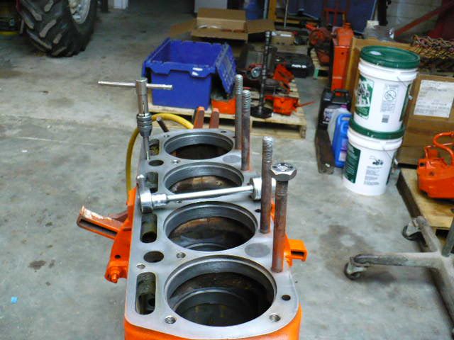 ------------- 3 WD45's with power steering,G,D15 fork lift,D19, W-Speed Patrol, "A" Gleaner with a 330 corn head,"66" combine,roto-baler, and lots of Snap Coupler implements to make them work for their keep. |
Posted By: SteveM C/IL
Date Posted: 04 Aug 2016 at 11:14pm
| ANNUAL. Gotta remove the 2 middle leters |
Posted By: Allis dave
Date Posted: 05 Aug 2016 at 6:53am
|
Thanks Don, always good to hear your comments. Very nice clean looking block Mine started off looking that clean after the hot tank. Then I'd go out and see a little surface rust starting on the gasket surfaces so I oiled them. Then they get wiped off with a break clean rag and cleaned with a scotch Bright on the die grinder. Then I blow everything out again with the air hose before assembly. See Blake? I think you can do a shim job Is there something wrong with the cam that it needs reground? Unless they've sat and rusted, I don't really hear of people having problems with them wearing. |
Posted By: Allis dave
Date Posted: 05 Aug 2016 at 7:10am
|
It been a pretty slow rebuild process. It started off with a split to replace seals in the torque tube. You can read about it here if interested http://www.allischalmers.com/forum/forum_posts.asp?TID=120328&title=how-to-or-not-to-split-wd45-replace-seals" rel="nofollow - http://www.allischalmers.com/forum/forum_posts.asp?TID=120328&title=how-to-or-not-to-split-wd45-replace-seals Then one Sunday last April I had to drive out to ILL to meet forum member John D and pick this up. It's a little motivation to get this project completed. http://s1359.photobucket.com/user/dmckinney45/media/Snap%20Disk_zpstptyihil.jpg.html" rel="nofollow">  Last night I couldn't work either. Was too busy watching this guy. http://s1359.photobucket.com/user/dmckinney45/media/Plane_zpsyzrec7jv.jpg.html" rel="nofollow">  |
Posted By: John D
Date Posted: 05 Aug 2016 at 7:39am
|
Looking good! Keep us posted on your progress ------------- 1964 D17 series 3 |
Posted By: Allis dave
Date Posted: 05 Aug 2016 at 7:58am
|
I should also mention that all holes in the block get blown out with the air hose, have a tap ran through them, then blown out again. All parts are from a Reliance/PowerMax kit. I had the engine internally balanced before I started. $350 including surfacing the flywheel. There was 15 gram difference from the lightest to the heaviest piston. Guy said the flywheel and crank were terrible. He said he "pulled his hair out" to finally get it quieted down. I'm hoping for one smooth running motor! Ohh and "Don't mix up the pistons and wrist pins!!" I didn't take any pictures but I wiped out the newly installed cam bearings again and lubed them up with assembly lubed. Lubed up the tappets and dropped them into their places. Lubed up the cam and slid it in making sure to line up the timing marks. Ring Gap Even though they came as part of the 8.25 motor kit, I thought I should still check the ring gap. I Installed the spacer and oil rings onto the pistons. I got the ring started down into the sleeve then used the piston to push the ring down until the piston bottomed on the oil ring. I figured this would make sure the ring was square in the (round) hole. lol. All rings gapped at .019 - .022. The book says the gap should be .007-.014. That seemed really tight to me. The people I talked to and what I read said .014 minimum gap for a 4" bore. High performance engine take a wider gap, so I'll pretend this is a high performance Allis and be happy with .019 - .022. I can't change it anyway... http://s1359.photobucket.com/user/dmckinney45/media/WD45%20Rebuild/Rings_zpsqqivnuof.jpg.html" rel="nofollow">  Piston Preparation I oiled up the rings and pistons good and installed the rings with my ring pliers making sure each ring was 120 degrees from the adjacent ring. According to the instructions, each dot on the ring points to the piston top. I also used the chrome ring as the top ring. Made sure the rings were matched to the sleeve I gapped it in. I followed the service manual instructions to orient the rod and wrist pin correctly in the piston. This is what centers the wrist pin in the piston and keeps this from gouging the cylinder wall. VERY IMPORTANT You can see where he machined off to balance the pistons. Notice the arrow pointing to the front of the block for installation. http://s1359.photobucket.com/user/dmckinney45/media/WD45%20Rebuild/piston%20balanced_zpszariwqce.jpg.html" rel="nofollow">  |
Posted By: Don(MO)
Date Posted: 05 Aug 2016 at 8:15am
Yes Steve that's the word. lmao ------------- 3 WD45's with power steering,G,D15 fork lift,D19, W-Speed Patrol, "A" Gleaner with a 330 corn head,"66" combine,roto-baler, and lots of Snap Coupler implements to make them work for their keep. |
 SteveM C/IL wrote:
Posted By: 79fordblake
Date Posted: 05 Aug 2016 at 9:58am
| The cam looks in good shape but I was gonna give Bullet Cams a call and see if any improvements can be done to it for a stock build..if not I'll leave it alone. I dropped the head off this morning. Supposed to be around $350. If it needs absolutely everything close to $500. I asked about line boring and he said around $160 so I'm gonna do it and have the whole thing balanced. I'm just having head done right now I'll have to save up a little more money for the rest lol. |
Posted By: ac45dave
Date Posted: 05 Aug 2016 at 6:19pm
------------- 54 wd-45gas ; 56 wd-45d N/F w/fact p/s ; 63 d-17 sIII N/F gas ; 60 D14 N/F ; 67 d-17 sIV N/F gas ; 63D15 sII W/F; 39rc#667 ; 2021 massey 4710 fwa ; gravely 2 wheel tractors |
Posted By: Allis dave
Date Posted: 05 Aug 2016 at 7:57pm
|
Dave,
LOL I guess it was me. John said he had another guy calling about it. You gotta be fast on the phone! I'd been looking for one for a few years now. I don't see as many 9 footers as 7's. Looking forward to being able to drive it on a trailer and take to plow days. I'm a fan of trying to take equipment other than just plows.I feel a little bad now. But not bad enough to let you have it.... John, You wouldn't believe how many times I've pulled of pieces of that baling wire in the back of the truck for some odd use. I'm about ready to drive back just to get some more! Don, One thing keeps bugging me, why is there a bolt head sitting on top of one of the studs in your picture of Mike's engine? Did you weld it on to remove the stud? I can see the sleeves. Looks like it turned out good. After looking at mine more. It was only pitted right up to were the top oring sits.I think it will still get a good seal.
|
Posted By: Don(MO)
Date Posted: 05 Aug 2016 at 10:50pm
|
Dave that not a nut, it's a 1/2" fine thread die to clean the threads up with. I changed all the studs out on the engine after trying to clean them up. If the threads or sides of the bolts or studs are not good you might pull them and find your are pulling the head back off to change them. happens on old head bolts/studs a lot.
------------- 3 WD45's with power steering,G,D15 fork lift,D19, W-Speed Patrol, "A" Gleaner with a 330 corn head,"66" combine,roto-baler, and lots of Snap Coupler implements to make them work for their keep. |
Posted By: Sugarmaker
Date Posted: 06 Aug 2016 at 8:30pm
|
Dave, Great documentation on the build! So your using a 175 kit in a 45 block right? Should be a good runner. You have plans for this build? Been moving and or pulling AC's all day. That D17 you plowed with this spring, is doing a nice job kicking some butt on the track. Keep the pictures coming maybe someday I will use your info to build a engine! Regards, Chris ------------- D17 1958 (NFE), WD45 1954 (NFE), WD 1952 (NFE), WD 1950 (WFE), Allis F-40 forklift, Allis CA, Allis D14, Ford Jubilee, Many IH Cub Cadets, 32 Ford Dump, 65 Comet, 66 F100. |
Posted By: Allis dave
Date Posted: 08 Aug 2016 at 2:44pm
|
Rod and Piston Installation To start with, I had the rods and caps honed and checked for roundness. A wd45 doesn't have any rod bearing shims so I should be good to go. First thing I noticed was the new rod bearings were narrower than the old Clevite bearings. The old ones measured .530 and the new ones were .430 for a difference of .110. http://s1359.photobucket.com/user/dmckinney45/media/WD45%20Rebuild/Rod%20bearings_zpsezbouxbg.jpg.html" rel="nofollow">  I used a ring compressor and slid the new pistons in place, making sure to put the correct piston in the correct hole with my marked arrow facing the front of the motor. Once in place, I verified that the wrist pin was slid the correct direction to not gouge the sleeve. I matched the correct rod to cap and made sure the stamped numbers were on the same side and torqued them down to 40ft lbs. A couple of the self locking nuts could be spun on with just my fingers, so I ordered a couple new ones from AGCO to make sure they locked well. I later found out from Don(MO) and Josh Day they I could lay the nuts out on an anvil and get a smaller sized socket to cover the locking "fingers" and give the socket a soft wack to tighten the fingers back up. Then use a dab of red Loctite on the nuts to make sure they stay in place. I'll actually have a chance to do this later, but I don't want to talk about it today... I plastigauged each bearing and came up with .002 - .003 on each one. http://s1359.photobucket.com/user/dmckinney45/media/WD45%20Rebuild/8.25%20piston_zpslzglw3uq.jpg.html" rel="nofollow">  You can see the piston is pretty close to the top of the sleeve. The deck clearance measures about .230. These 8.25 pistons should make a lot of power as long as everything holds together. I don't plan on using them to pull the poor tractor to the max. I'll use it on the same size plow to get through the hard spots and maybe an occasional local farm stock pull. http://s1359.photobucket.com/user/dmckinney45/media/WD45%20Rebuild/8.25%20piston%20deck%20height%20230_zpsammiaixb.jpg.html" rel="nofollow">  I really like the 65cc piston cup to compress a good air/fuel charge around the spark plug versus the much shallower 32cc bowl used for the Reliance 7.25 D17 piston. The old M&W's I took out had an even larger 73cc bowl. |
Posted By: 79fordblake
Date Posted: 08 Aug 2016 at 5:15pm
| What head gasket are you using? I may try finding one that is a little thinner than the one in my gasket kit. You going to use a D17 governor spring? I ordered new connecting rod nuts as well. I cleaned and painted timing cover over the weekend and replaced the throttle shaft bushings. |
Posted By: Allis dave
Date Posted: 09 Aug 2016 at 8:15am
| Blake, sounds like you're making good progress. Making sure you have everything checked out and cleaned up first makes the assembly a lot easier. I'm learning that... I'm using the head gasket that came with the reliance kit. If I was you, I'd get a Victor Reinz gasket set. It has a better head gasket (copper rings around all the water and oil gallys). They also have the correct front main seal. |
Posted By: Allis dave
Date Posted: 09 Aug 2016 at 9:53am
|
Timing cover I cleaned up the timing cover good and checked the throttle bushings and governor fingers. The bushings are tight. The fingers show a little wear, but I don’t think bad enough to need welded and ground back down. Be careful when handling the cover. If you bend the linkage arm it will throw your carborator out of adjustment and cause surging or other issues. I used a scotch bright disk on the end of my die grinder to clean the gasket surfaces. I tested on a pop can to make sure the pad wouldn’t take off metal. I bought the wrong pads once that contained grit and would take off metal. I tried to make up an alignment tool out of PVC like Don suggested but wasn’t finding the right stuff. I found this bearing collar for about $7. It was the right size but needed touched up a little on the lathe. Gay at work took it home and fixed it up for me. He charged me a cherry pie pastry for the work. I actually bought him 4. Total $9 http://s1359.photobucket.com/user/dmckinney45/media/WD45%20Rebuild/Alignment%20Tool_zpsiiy7cakn.jpg.html" rel="nofollow">  I slid the alignment tool into the cover and painted on a thin layer #3 permatex onto both sides of the gasket and bolted the cover into place. I probably didn’t need sealer, but I feel better knowing any little pits are filled. I hate leaks. I like to #3 for this purpose because a thin layer can be painted on without a lot of oozing. The gasket kit with the Reliance kit only had 2 front main seal. One that was way to big, and one that seemed the right size and had an extra felt protective layer on the outside. The service manual says newer (1950’s newer I suppose) seals have the felt to protect the seal. Apparently this is NOT that seal. It could all I had to get it on the crank and pretty much ruined the seal. A call to my reliance dealer and he says that’s a slightly smaller seal for a WD crank. He sent me 2 of the correct seals. I quick look at my old leftover Victor Reinz and I still have the too big seal (probably for a D17) and the too small felt covered seal. Looks like that kit cam with all 3 seals and I already used the correct one previously. WD Seal, It's a little beat up, this is after I starting trying to get it back off http://s1359.photobucket.com/user/dmckinney45/media/WD45%20Rebuild/Front%20Seal%20small_zpsxgvulqso.jpg.html" rel="nofollow">  I chamfered the end of the crank a little to help get the seal started. I oiled up the seal and shaft good. Apparently I didn’t chamfer enough because I rolled over a small part of the seal. Really chamfered the heck out it next time and the seal went on well. HEY, that alignment tool works great to tap the seal in place too. http://s1359.photobucket.com/user/dmckinney45/media/WD45%20Rebuild/Front%20Seal%20Install_zpsbzvmh8wm.jpg.html" rel="nofollow">  |
Posted By: 79fordblake
Date Posted: 09 Aug 2016 at 12:19pm
| The victor set is what I got and some of it seems poor quality. The (F) gaskets for under the main cap are wrong. Sandy Lake Implement is currently trying to find out for me if the Agco oil pan kit comes woth the correct ones. I made a tool from a pipe I had laying around to center timing cover when I get to that point. |
Posted By: Allis dave
Date Posted: 09 Aug 2016 at 12:54pm
| I know for sure that a felpro main kit comes with both sizes of F gaskets. I'm not sure about the Felpro oil pan gasket kit. I ordered one today from NAPA and will have it to tomorrow. $16. I'll let you know what's in it. |
Posted By: DrAllis
Date Posted: 09 Aug 2016 at 1:08pm
| I always take a piece of good quality black electrical tape and thinly wrap it around the crankshaft snout like a barber pole. Keep overlap to a minimum and start away from the crank end and spriol to the end. Spray some WD-40 on the tape and slide the oil seal onto the shaft and have no fear of cutting the seal when going over the setscrew holes or half-moon keyway. Remove tape when seal is installed. |
Posted By: 79fordblake
Date Posted: 09 Aug 2016 at 2:24pm
| Dave what was the number for the felpro rear main kit? I already have a entire kit so if i don't have to spend the money on a Agco oil pan kit to get the F gaskets that would be great. |
Posted By: Allis dave
Date Posted: 09 Aug 2016 at 2:39pm
|
Here's the link to NAPA's site. part# FPG BS40010 https://www.napaonline.com/napa/en/p/FPBBS40010/FPBBS40010_0232675384" rel="nofollow - https://www.napaonline.com/napa/en/p/FPBBS40010/FPBBS40010_0232675384 Thanks for the tip Doc. That's a good idea. |
Posted By: Sugarmaker
Date Posted: 09 Aug 2016 at 9:34pm
|
Dave, Your coming right along and helping others during your journey! Regards, Chris ------------- D17 1958 (NFE), WD45 1954 (NFE), WD 1952 (NFE), WD 1950 (WFE), Allis F-40 forklift, Allis CA, Allis D14, Ford Jubilee, Many IH Cub Cadets, 32 Ford Dump, 65 Comet, 66 F100. |
Posted By: Allis dave
Date Posted: 10 Aug 2016 at 11:35am
|
Oil Pump For my Full Flow oil system conversion I purchased a used oil pump from Bill Deppe with internal regulator and it already had the 10 tooth gear. Great working with Bill by the way. Would definitely buy parts from him again. There was a little bit of junk between the screen and cover so I took the cover off and sprayed the pump and cover out really good with the water hose. After I installed the pump I kept having a nagging feeling that I should've pulled the cover and checked it out. I'm glad I did because I found a relief valve spring with about 1/2" broken off the end. Purchased a new one from AGCO for $7 and it came drop shipped from MinnPar in a MinnPar box. Guess where some AGCO "OEM" parts are sourced from??? The new spring was a little thinner, but also longer. Hopefully the difference is a wash and I get 30PSI from it. Once it's together there's no changing it without dropping the pan, unlike a standard WD45 with the pressure valve in the side of the bock. Once I was in there I decided to pull the drive shaft out and check it for wear. To pull the shaft I had to drive the roll pin out of the gear. The gear is also lightly pressed onto the shaft so I drove the shaft off the gear with a brass punch. I got lucky during re-assembly and managed to get the roll pin holes perfectly lined up after tapping the gear back onto the shaft with a block of wood and hammer. The picture makes it look like more wear than what's really there. The shaft was perfectly smooth with no wear spots. I had more than one person tell me that these old oil pumps never die. I guess they were right. They never said anything about relief valves...  http://s1359.photobucket.com/user/dmckinney45/media/WD45%20Rebuild/pump%20shaft_zpsjozzxwze.jpg.html" rel="nofollow">  http://s1359.photobucket.com/user/dmckinney45/media/WD45%20Rebuild/pump_zpsrqsx17io.jpg.html" rel="nofollow">  With the method I chose, I had to make a new oil line to go form the pump to block. I tried not to pinch the line while bending. I think I did ok. I'll make a new post about the full flow conversion one of these days. http://s1359.photobucket.com/user/dmckinney45/media/WD45%20Rebuild/pump%20installed_zpssx95xrr5.jpg.html" rel="nofollow"> 
|
Posted By: Brian Jasper co. Ia
Date Posted: 10 Aug 2016 at 11:59am
------------- "Any man who thinks he can be happy and prosperous by letting the government take care of him better take a closer look at the American Indian." Henry Ford |
Posted By: Brian Jasper co. Ia
Date Posted: 10 Aug 2016 at 12:06pm
|
Looks good Dave. Do all of the connecting rod clamp bolts face the same side and you just position the rods on the pins in order to have everything line up correctly? ------------- "Any man who thinks he can be happy and prosperous by letting the government take care of him better take a closer look at the American Indian." Henry Ford |
Posted By: 79fordblake
Date Posted: 10 Aug 2016 at 5:26pm
| Did you get new rod bolts or just nuts? My bolts don't appear to have any damage the nuts are fine to other than they look like a socket may have slipped on them some so I just went ahead and got new. Did you get your gasket kit yet? |
Posted By: Allis dave
Date Posted: 11 Aug 2016 at 7:03am
|
I got the full Felpro oil pan gasket set last night. I includes the 2 long gaskets, the 2 short gaskets you stick in a can to curve, the main seals and the small F gaskets for a 45. $17 part# FPG OS30130C I already had Felpro main gasket set part# FPG BS40010. It included the rear main seals, upper main carrier to block gasket, and the F gaskets. $12 I bought a new set of head studs, when I got looking at my old head bolts, someone mixed a set because 4 were grade 2's in there! They should be grade 5's or better. Like Don says make sure all the threads are good and the bolts don't have any pitting. Brian, All the wrist pin bolts face toward the cam side. cylinders 1,3 and 2,4 are the same I believe. Depending on which cylinder you're going in, you slide the pin to one side of the piston or the other and slide the rod over until it touches the piston on that side. Then the wrist pin can't get over far enough to gouge the sleeve. The crank/rod position pulls the pin opposite direction a little to center the pin. The service manual spells it all out with pictures. I wouldn't install the pins without staring at the book. |
Posted By: Don(MO)
Date Posted: 11 Aug 2016 at 7:34am
|
Like Dr Allis using tape I cut a thin (.002") piece of brass shim stock to just fit around the shaft then rap it around the shaft starting with it about 1/4" ahead of the front end shaft and ending it just short of where the seal starts to inter the front cover, I also pack the back inside of the seal with grease, that will help hold the spring in place and wipe some grease inside on the seal lip. One thing I have found over the years is; most wrench's will have some little tip they use and have good luck with, so I say find the one's you like and take the time to rebuild it right and the build will last along time. ------------- 3 WD45's with power steering,G,D15 fork lift,D19, W-Speed Patrol, "A" Gleaner with a 330 corn head,"66" combine,roto-baler, and lots of Snap Coupler implements to make them work for their keep. |
Posted By: Allis dave
Date Posted: 11 Aug 2016 at 11:50am
|
Oil Pan Installation First off, if you haven't watched DonMO's oil pan gasket video. Watch it! Even if you're not rebuilding and are just bored one night, watch it. http://www.allischalmers.com/forum/forum_posts.asp?TID=93356&title=oil-pan-gasket-video" rel="nofollow - http://www.allischalmers.com/forum/forum_posts.asp?TID=93356&title=oil-pan-gasket-video I won 't try to re-explain everything in the video, but here's the quick run down, of what I did. Clean up the pan and block with my trusty die grinder and scotch bright pad. The pan was straight and the corners measured in spec so pretty simple preparation. I ran a tap through all the holes. There was one spot on the pan between 2 bolt holes that I could feel a small dip, so later I put a little extra sealer in that spot. After sitting for a couple months in a pear can, previously full of delicious pears, the main end gaskets held their share very well. I never knew the gasket clips existed before. They make holding the gaskets in place a breeze. http://s1359.photobucket.com/user/dmckinney45/media/WD45%20Rebuild/pna%20gasket%20clips_zpsa0jwtsep.jpg.html" rel="nofollow">  I made 4 alignedment studs by butting the head off of a few bolts which made installation much easier also. I laid out the gaskets on the block and made a few lines with a marker where I wanted the gaskets to sit. After removing the gaskets, I put a thin layer of #2 permatex on the block to stick the gaskets to. I laid the gaskets back in their place. Then I put another thin layer of permatex on top of the gasket to seal and pan imperfections. I put a little extra in that spot where the small dip was on the pan gasket area. I probably didn't need the extra sealer, but I know it won't leak. http://s1359.photobucket.com/user/dmckinney45/media/WD45%20Rebuild/pan%20gasket_zpsxwcwvybu.jpg.html" rel="nofollow">  I put a good dab of sealer in the 4 corners where the gaskets meet. If you don't put a little sealer in these corners, I don't see how the gaskets would ever seal well. You can see I didn't put globs on. Just enough to seal the corners and any surface imperfections. Hopefully NO LEAKS http://s1359.photobucket.com/user/dmckinney45/media/WD45%20Rebuild/pan%20gasket%20seams_zpseuwmnlxp.jpg.html" rel="nofollow">  It takes quite a bit of tightening to get the end gaskets drawn down good. I went around the pan about 4 times tightening a little at a time with a 1/4 ratchet, because I have a tendency to over tighten. I imagine you could twist the pan by initially tightening down in only a few places. I ending up with the torque wrench and tightened down to 10ft lbs. In Don's video he said 18lbs, but just 10lbs felt like a good amount on these little grade 2 5/16 bolts. Everything looked like it was squeezed down good, so I stopped there. The manual doesn't even give a torque spec and I imagine over-tightening is worse here than under-tightening here. |
Posted By: ac45dave
Date Posted: 11 Aug 2016 at 12:14pm
Dave,looks like things are coming right along.keep the posts and pics coming.enjoy watching the progress. ------------- 54 wd-45gas ; 56 wd-45d N/F w/fact p/s ; 63 d-17 sIII N/F gas ; 60 D14 N/F ; 67 d-17 sIV N/F gas ; 63D15 sII W/F; 39rc#667 ; 2021 massey 4710 fwa ; gravely 2 wheel tractors |
Posted By: Allis dave
Date Posted: 12 Aug 2016 at 7:59am
|
All of the previous posts were work already completed that I hadn't got time to post. Now I'm up to current where the motor sits now. Today I'll talk about some of my mistakes that I'd rather leave unsaid, but sometimes we learn more from what we do wrong than from what we do right. Hopefully some other green people like me can learn from my mistakes and not repeat them. Lessons Learned I've really been going about this rebuild the wrong way. I've been treating it as a bunch of "stages" as I've gotten time to work on it over the last few months instead of one large project. For example, I waited to clean up and disassemble the oil pump until the day I was going to install. I found the broken spring and had to pay shipping and wait for just one spring. Had I checked all my parts before starting assembly, I could've had less part orders and a quicker assembly. I'll say now that preparation is the key! When Don says start with a clean block, START WITH A CLEAN BLOCK. don't do like I have and wait to tap out the oil pan boles holes until you install the oil pan or the head holes when you install the head. This makes it a lot harder to keep the block clean when you are always introducing dirt. Also clean ALL of the gasket surfaces first. If you are worried they will rust, apply some oil after they are clean and clean off with a rag soaked in breakclean later. Don't introduce all that dirt into your block when parts are already in it. Same is true even if your block was hot tanked like mine was. Now I'm just stalling... Since I didn't prep well, I waited to clean up my head bolts until I was going to install the head. When cleaning, I quickly noticed that 3 or 4 of the head bolts were only grade 2! Maybe that's partly why I was having some head gaskets issues... I'd been on the fence about new head bolts before, but now I knew I should just remove the existing studs and buy ALL new matching studs/bolts. I went and borrowed a stud remover and pulled the 3 3/8's studs. One came out pretty hard but didn't break. Moved on to the 2 1/2 studs where the thermostat sits. The first one turned HARD. I walked back with a pipe to put on the 1/2 ratchet, and hope I didn't break the stud, when I realized I was tightening the stud instead of loosening. I went the correct way and the stud came out, only to let me see that while I was tightening the stud, the stud remover was drawing down on my block and sleeve making a nice gouge in my nice new sleeve! http://s1359.photobucket.com/user/dmckinney45/media/WD45%20Rebuild/Sleeve%20Scrape_zpsw0m5azlg.jpg.html" rel="nofollow">  Had I cleaned and inspected the bolts BEFORE I wouldn't have had this problem even if I did tighten the stud. Luckily FredPA was able to find me another one of these rare 4" sleeves. Everything will be made right, but all completely avoidable... I will save the sleeve and maybe have a couple thousandths turned off of it and pack it away as a spare. I'm sure someone will need one someday. When I have the oil pan off again, I'll also use this time to pull out the rod bolts again and tighten up any of the nut "locks" that are a little looser than I'd like and add a drop of red Loctite before tightening. The last thing I would've done differently is to have the block decked and recut the counterbores to make a perfect block. I bought a straight edge and some spots I only have .001 standout when I get farther to the edge of the block. Generally I'm at .0015-.003. I'll probably be fine, but I'd feel better knowing it was perfect. So I guess, don't cut corners, prep, and plan well! Well the motor goes back into the bag for the night. The dog was excited, I let her in the shed for a couple minutes. She tends to cause more harm than help if she's in there too long. http://s1359.photobucket.com/user/dmckinney45/media/WD45%20Rebuild/Covered_zps0kecrfw6.jpg.html" rel="nofollow">  |
Posted By: Don(MO)
Date Posted: 12 Aug 2016 at 9:25am
|
Dave looks like you have learned a lot along the way of your own engine rebuild. good job. I'll bet you will rebuild the next one a lot faster. I have not posted all the little tips that help me, so here's a little tip I do on the head rebuilding, I strip all the guides, manifold studs and have the top, bottom and the manifold side of the head all trued, that helps stop coolant leaks around the thermostat housing and back two bolt cover to head, valve cover and manifold. Keep your posts coming it's nice to see someone learn old tractors. ------------- 3 WD45's with power steering,G,D15 fork lift,D19, W-Speed Patrol, "A" Gleaner with a 330 corn head,"66" combine,roto-baler, and lots of Snap Coupler implements to make them work for their keep. |
Posted By: SteveM C/IL
Date Posted: 12 Aug 2016 at 1:08pm
| Experience is a great teacher....sometimes it teaches hard lessons.Worst part for me is by the time I do it again,I've forgotten some of the pit falls and learn the hard way ....AGAIN! |
Posted By: Sugarmaker
Date Posted: 12 Aug 2016 at 9:55pm
|
Dave, Good documentation and lessons learned too! Beefy tires you have on the WD45! Its going to be a good strong running tractor! Regards, Chris ------------- D17 1958 (NFE), WD45 1954 (NFE), WD 1952 (NFE), WD 1950 (WFE), Allis F-40 forklift, Allis CA, Allis D14, Ford Jubilee, Many IH Cub Cadets, 32 Ford Dump, 65 Comet, 66 F100. |
Posted By: Allis dave
Date Posted: 15 Aug 2016 at 8:12am
|
I didn't get(make) much time to work on this thing over the weekend. Still waiting for parts to be delivered too. Head work I put the head together about a month ago. I had the bottom and manifold side of the head milled. Manifold was also milled to true it up. All new valve train was installed, so new valves, guides, springs, and retainers. They weren't too bad, but I also had new hardened seats installed. The only thing I didn't think to do was to have the top of the head milled. I had no leaks there before so I should be fine, but it would've been a nice extra. I spent about 10 minutes with the air nozzle blowing any junk out of the passages that I could break loose. I got some valve grinding compound and lapped each valve into it's new home. As expected with new valves and seats, they lapped in perfect. I carefully cleaned up all the grinding compound and lubed the valve stems. I also cleaned up the spring seats good and oiled them up. I used my free spring compressor that an old tenant left behind to install the spring, spring seat, cap and retainer. This head had the valve rotating caps for the exhaust valves. http://s1359.photobucket.com/user/dmckinney45/media/WD45%20Rebuild/Valve%20Lapped_zpswwmijxlb.jpg.html" rel="nofollow">  http://s1359.photobucket.com/user/dmckinney45/media/WD45%20Rebuild/Head%20Bottom_zps4vxyhvxa.jpg.html" rel="nofollow">  http://s1359.photobucket.com/user/dmckinney45/media/WD45%20Rebuild/Head%20Top_zpsxppa5brw.jpg.html" rel="nofollow">  I did take the thermostat and front water jacket block cover to work and sanded them back flat on the granite block. They were pretty off! http://s1359.photobucket.com/user/dmckinney45/media/WD45%20Rebuild/Thermostat_zpstquwcogn.jpg.html" rel="nofollow">  http://s1359.photobucket.com/user/dmckinney45/media/WD45%20Rebuild/Water%20Cover_zpsre31ctud.jpg.html" rel="nofollow"> 
|
Posted By: Don(MO)
Date Posted: 15 Aug 2016 at 8:25am
|
Dave you might test fit the manifold to the head before installing the head, I have seen the carb shaft rub the side of block after head and manifold milling.I'd set the head on the block and set the manifold on with the carb bolted on and check it. It might be good to go I'm just saying check it. lol ------------- 3 WD45's with power steering,G,D15 fork lift,D19, W-Speed Patrol, "A" Gleaner with a 330 corn head,"66" combine,roto-baler, and lots of Snap Coupler implements to make them work for their keep. |
Posted By: Allis dave
Date Posted: 15 Aug 2016 at 9:21am
|
Thanks Don, I'll make sure to test fit that. Do you have any tips to get the manifold lined up? There's a lot of room to slide it around on those 3/8's studs. |
Posted By: Don(MO)
Date Posted: 15 Aug 2016 at 12:13pm
|
If the old manifold is been milled to the point the carb is rubbing the block I have it re-milled about 95* angle not the normal 90* or let the top or the manifold lean to the right of the tractor a little, if you go to far with the milling the hood will hit the muffler. Or just get a new one. ------------- 3 WD45's with power steering,G,D15 fork lift,D19, W-Speed Patrol, "A" Gleaner with a 330 corn head,"66" combine,roto-baler, and lots of Snap Coupler implements to make them work for their keep. |
Posted By: Allis dave
Date Posted: 15 Aug 2016 at 12:42pm
| Sorry, I meant, when you install the manifold, there is a lot of room to shift the manifold, up & down, or left to right on the studs. Is there a way and is it beneficial to try to get the manifold centered so the ports transition correctly, or should I just put the nuts on and not worry about it. This is all IF there are no clearance issues. |
Posted By: SteveM C/IL
Date Posted: 15 Aug 2016 at 2:08pm
| I just center the studs in the holes |
Posted By: Allis dave
Date Posted: 15 Aug 2016 at 2:20pm
| Thanks, that's how I've done it in the past, but I thought maybe there was a better way. |
Posted By: Don(MO)
Date Posted: 15 Aug 2016 at 7:19pm
|
You are OK with a stock manifold and no porting of the head to do it like Steve said.
------------- 3 WD45's with power steering,G,D15 fork lift,D19, W-Speed Patrol, "A" Gleaner with a 330 corn head,"66" combine,roto-baler, and lots of Snap Coupler implements to make them work for their keep. |
Posted By: Allis dave
Date Posted: 17 Aug 2016 at 9:22am
|
My new ARP head studs came yesterday. The ARP studs are overkill compared to the original grade 5 head bolts, but I decided that it's worth it to me to have a high quality fastener that will torque down as a perfectly matched set. I think it's even more important with the higher compression that I'll be running. I put them all in the block last night for a test fit. a few of them are too short so I'll have get a few different ones. Now I know the correct and incorrect way to measure for studs before buying... I'll post the correct sizes once I get everything correct. The 1/2 studs go a lot deeper into the head which should give some extra thread strength They are beautiful studs. http://s1359.photobucket.com/user/dmckinney45/media/WD45%20Rebuild/Head%20Studs_zps3jvfrxi9.jpg.html" rel="nofollow">  I cut a strip of cardboard and laid it on the block over the cylinders for a layer of protection and set the head on for a test fit. I put in two manifold studs and put on the manifold and carburetor. The carburetor and choke rod didn't hit the block, so the head and manifold weren't milled too much. When I set the rocker assembly on the head, I found that the stud nuts and washers are the little thicker than the bolt heads were so the end of the rockers assembly sat on top the nut and was help up about .100. If I use the nut with no washer It just barely clears. I should've taken a picture... I think I'm going to pull the valves back out of the head and have the valve cover surface milled a little and have the machinist take a about .200 off the 2 separate head stud bosses under the ends of the rocker arms. I looked and can't find the gaskets that go under the thermostat housing or front water jacket block cover so I'll be doing like Dr. Allis suggests and just putting some sealer there. Having the top surfaced should make sure I can make a good seal there. http://s1359.photobucket.com/user/dmckinney45/media/Head%20test%20fit_zpsvkl9i7lh.jpg.html" rel="nofollow"> 
|
Posted By: Don(MO)
Date Posted: 17 Aug 2016 at 10:12am
|
Dave, before you pull the valves and send it back to the shop I'd call them and ask if they can go around the guides. I have the top of 201/226 heads done with the guides out makes it a one time pass over the top, just saying call before you go to that work. You might be better off to reorder bolts under the rocker arms, you will need to use the washers on the head with ARP bolts or studs and nuts. I can see what your head bolt holes looks like without seeing it, the bolt holes are not nice they might even have pieces of the head gone around them that's why I said to use the washers. You are going at it right so stay in-there you will have a nice engine when you are done with it. ------------- 3 WD45's with power steering,G,D15 fork lift,D19, W-Speed Patrol, "A" Gleaner with a 330 corn head,"66" combine,roto-baler, and lots of Snap Coupler implements to make them work for their keep. |
Posted By: Don(MO)
Date Posted: 17 Aug 2016 at 10:16am
|
I for got to say change the two head bolts at the end of the rocker arm shaft too.Studs,washers and nuts will hit the shaft too. ------------- 3 WD45's with power steering,G,D15 fork lift,D19, W-Speed Patrol, "A" Gleaner with a 330 corn head,"66" combine,roto-baler, and lots of Snap Coupler implements to make them work for their keep. |
Posted By: ac45dave
Date Posted: 17 Aug 2016 at 10:25am
|
you go dave!!!dave, just a thought,is it the outer diameter of the washers that's not clearing?if so, wouldn't be simpler to cut down the diameter of the washers to get your clearance? never mind dons got ya covered.guess i type too slow,lol. ------------- 54 wd-45gas ; 56 wd-45d N/F w/fact p/s ; 63 d-17 sIII N/F gas ; 60 D14 N/F ; 67 d-17 sIV N/F gas ; 63D15 sII W/F; 39rc#667 ; 2021 massey 4710 fwa ; gravely 2 wheel tractors |
Posted By: Don(MO)
Date Posted: 17 Aug 2016 at 10:33am
If have the time and just looking for right as rain (as Dad used to say) set a manifold gasket on all the ports and center them to the port draw a line around them , use the lines to center the manifold to head. ------------- 3 WD45's with power steering,G,D15 fork lift,D19, W-Speed Patrol, "A" Gleaner with a 330 corn head,"66" combine,roto-baler, and lots of Snap Coupler implements to make them work for their keep. |
Posted By: Allis dave
Date Posted: 17 Aug 2016 at 11:04am
|
It's the two studs/nuts at the end of the rocker shaft that don't clear. Dave, It's not the diameter of the washers that doesn't clear, it's that the thickness of the nut and washer together is thicker than the old bolt head. When I set on the rocker assembly, the shaft sits down on top of the nut. Lets say the rocker shaft sits .600 above the head, well the nut and washer are .700. Don, When I was trying to eyeball with a straight edge last night, it looks like the guides are a little below the valve cover surface. Are they usually above? When I was at the shop yesterday, he said he'd have to push the guides out if they were above the surface. No wonder you've got so many tractors lined up for repair. You never get to work on them because you're too busy helping us. lol |
Posted By: DrAllis
Date Posted: 17 Aug 2016 at 6:37pm
| Be sure to mark the flywheel for 25 degrees BTDC instead of the 30 degrees it is now, if you are using D-17 pistons/sleeves. |
Posted By: Allis dave
Date Posted: 18 Aug 2016 at 8:02am
|
Thanks Doc, I was planning on setting timing to 23degrees. These are 175 pistons. |
Posted By: Allis dave
Date Posted: 14 Sep 2016 at 8:56am
|
Finally got the rest of the parts and head work done and now back to work. I'm not sure which takes longer, the actual work, or the posting. Head Studs The final head stud sizes I used are as follows: 4- 1/2 x 6.120 5- 1/2 x 5.750 3- 1/2 x 5.250 3- 3/8 x 5.150 The ARP studs seems to be very high quality fasteners. Beautiful studs with nice flanged nuts, and good washers. I borrowed and re-ran a bottom tap through all the holes in the block to get a couple extra threads holding onto the studs. I had to cut a little off the 2 studs under the end of the rocker arm to clear. I also cut a little off the center stud under the rocker arm. I almost touched the rocker arm spring and I was worried maybe they touch and wear the spring through over time. The 6.120 studs went under the thermostat and water jacket blocking cover. They were just barely long enough under the thermostat. I didn't use a gasket there. If I had, 6.120 wouldn't have been long enough. Next size longer was on backorder. http://s1359.photobucket.com/user/dmckinney45/media/WD45%20Rebuild/45174ea6-1add-4fe0-8a1c-7eb75e2345cc_zpso2gdsl0u.jpg.html" rel="nofollow">  I lightly oiled the threads and official installed the studs finger tight into the block. http://s1359.photobucket.com/user/dmckinney45/media/WD45%20Rebuild/Head%20Studs_zps3jvfrxi9.jpg.html" rel="nofollow"> I took the head back to the machine shop and they took .010 off the top valve cover surface. That should make sure it's trued up good and the thermostat housing and front water jacket cover seal good. Then he threw the head into the mill and touched up the center stud bosses to make sure they were perfect. Most importantly, he cut a little down into the two stud bosses under the end of the rocker arms to make room for the stud and nuts. Still not enough room for a nut and washer so I'll just use the nut. With a good flat surface and some special ARP lube it should be ok. http://s1359.photobucket.com/user/dmckinney45/media/WD45%20Rebuild/Stud-Rocker_zpsfvgiyqil.jpg.html" rel="nofollow">  |
Posted By: Allis dave
Date Posted: 16 Sep 2016 at 9:05am
|
Head Installation I got the head put on last weekend too. I was reading through some old posts about if I should put and type of sealer on the head gasket. Lots of opinions out there about the copper coat, hi-tack, aluminum paint, and Red RTV sealer. I finally decided to put a light coat of High-Temp Red RTV sealer around all of the water jackets and oil ports. This block always seeped oil out the push rod side (before the head was milled) so I thought this might be a good way to keep everything where it's supposed to be. Because the coolant passages in the head gasket on the push side are sized smaller than the block passages to regulate flow, I put the sealer on the block here instead of the on the gasket. Did the same on the head. http://s1359.photobucket.com/user/dmckinney45/media/WD45%20Rebuild/Deck%20Sealer_zpsbfdlx4r6.jpg.html" rel="nofollow">  Here you can see my coating on the head gasket. I did the same to the bottom. The gasket will crush down pretty good so I only put a very light coating and smeared with my finger and wiped off the excess. I take it as a good "sign" because it almost looks like Persion orange in the picture I also didn't notice until I was looking at the picture that I didn't put any sealer around the blocked off coolant passages. It wasn't intentional, I just didn't think about them leaking since they blocked.  http://s1359.photobucket.com/user/dmckinney45/media/WD45%20Rebuild/Head%20Gasket_zpsf0t6gw9f.jpg.html" rel="nofollow">  I set the head on the block and squeezed a bead of special coolant gasket sealer for water pumps and thermostat on the head around the water jackets for the thermostat housing and the jacket blocking cover. I didn't use gaskets here because Doc said not to because he's seen them squeeze out under the head stud torque. My studs at the thermostat weren't long enough for an extra gasket layer anyway. When I flattened out the t-stat housing and block cover by sanding, I could see the blocking cover was humped in the center pretty good I assume from the ends of the gasket crushing more than the center. No, no gaskets seemed like a good idea. Both surfaces are flat so I shouldn't have any leaks. Doc said he doesn't. A tube of ARP's special lube paste came with the studs so I lubed up both sides of the washers and the stud bosses where I don't have room for a washer. I lubed up the stud threads and the nut flare and put them on finger tight. That ARP lube is some slippery stuff! Torque values The WD45 Service manual says to torque 90lbs on the 1/2 studs and 25lbs on the 3/8 studs. ARP says their studs are rated for 110lbs and 45 lbs. I Didn't want to go that much because I don't know if the block would handle it OR crush the gasket too much. A D17 switched from 3/8 to 7/16 studs and torqued them to 70lbs. Since I have 175 pistons I figured a little extra torque would help and not crusht he gasket too much. A very good mechanic that I know said 25 seems very low for a 3/8 stud. After a little research on other applications, it seems like most 3/8's are torqued between 30-40. So... I finally decided to torque the 3/8 studs to 35lbs and 1/2 studs to 92lbs. I torques the nuts in 3 steps following the stud order in the service manual. I used 30lbs, 60lbs, and 92lbs steps for the 1/2 studs, and 12lbs, 24lbs, 35lbs for the 3/8's. To properly torque the nuts under the thermostat, I used this nifty wrench that Don helped me find. http://www.allischalmers.com/forum/forum_posts.asp?TID=115588&KW=thanks+don&title=wd45-engine-rebuild" rel="nofollow - http://www.allischalmers.com/forum/forum_posts.asp?TID=115588&KW=thanks+don&title=wd45-engine-rebuild After the last torque step, I hit them all again, then I went back again after a couple days and retorqued to see if anything was stretching. A couple of the nuts moved a little, but not too much. After the motor heats up and cools a few times I check them all again cold. Here's the head all installed and the motor ready to be painted. http://s1359.photobucket.com/user/dmckinney45/media/WD45%20Rebuild/Head%20Installed_zpsdsikkjmy.jpg.html" rel="nofollow"> 
|
Posted By: Sugarmaker
Date Posted: 18 Sep 2016 at 6:54am
|
Dave, Nice documentation on the 45 engine rebuild. I would like to build one some day. May need your help! Regards, Chris ------------- D17 1958 (NFE), WD45 1954 (NFE), WD 1952 (NFE), WD 1950 (WFE), Allis F-40 forklift, Allis CA, Allis D14, Ford Jubilee, Many IH Cub Cadets, 32 Ford Dump, 65 Comet, 66 F100. |
Posted By: Don(MO)
Date Posted: 18 Sep 2016 at 10:18am
|
Dave I hope you changed the two cork plugs in the ends of the rocker arm shaft. They are a #2 cork plug, drive them in just flush to the end of shaft and drill hole to install the cotter key. If you push them in pass the cotter key hole it will cover the rocker arm oil hole. Or cut about 1/8" off the little end of the cork and drive them in just pass the cotter key hole in the shaft. ------------- 3 WD45's with power steering,G,D15 fork lift,D19, W-Speed Patrol, "A" Gleaner with a 330 corn head,"66" combine,roto-baler, and lots of Snap Coupler implements to make them work for their keep. |
Posted By: Skyhighballoon(MO)
Date Posted: 18 Sep 2016 at 11:55am
|
Dave - I have not seen RTV red silicone used like that on a head gasket. Where is that excess going to go when you torque the head down? I would be afraid excess would squish out where you don't want it or it wouldn't have anywhere to go and you'd have a high spot were it wouldn't seal? Not an expert at this by any means. Mike ------------- 1981 Gleaner F2 Corn Plus w 13' flex 1968 Gleaner EIII w 10' & 330 1969 180 gas 1965 D17 S-IV gas 1963 D17 S-III gas 1956 WD45 gas NF PS 1956 All-Crop 66 Big Bin 303 wire baler, 716H, 712H mowers |
Posted By: Allis dave
Date Posted: 19 Sep 2016 at 8:32am
|
Don, I wasn't going to replace the cork because it looked ok. It's at least 35 years old though so I probably should. Mike, I figured there wouldn't be anymore (probably less) squish than painting with aluminum paint, hi-tack or copper coat and would only put sealer where needed. I used a pretty thin layer too. I'm not an expert either so I guess I"ll find out how it worked sooner or later. Doc recommended the Red RTV once in an old post. After reading the back of the RTV sealer tube it says not for use on head gaskets. So use at your own rick... |
Posted By: Allis dave
Date Posted: 26 Oct 2016 at 11:07am
|
Flywheel Timing I got the engine back from the painters and finally got a little time to start working on it again. Boy does that guy make a nice paint job! I needed to mark the flywheel for 25 degrees BTDC for the high compression pistons instead of the 30 degree WD45 30 degrees. I actually chose to mark at 23 degrees. There was a service bulletin once that stated to retard timing to 23 degrees is you had detonation issues. I chose to just start there. I downloaded a printable timing wheel and printed it out to 11.75" to match the flywheel. I taped it to a piece of cardboard and laid it out on the flywheel. http://s1359.photobucket.com/user/dmckinney45/media/WD45%20Rebuild/Timing%20Wheel_zpswjus5nqg.jpg.html" rel="nofollow">  I took a chisel and marked 23 degrees. I did this on both sided of the flywheel because I wasn't sure which was TDC and which was 180 degrees off and BTDC. I'll have to figure that out after I get the pushrods and rocker arm installed. http://s1359.photobucket.com/user/dmckinney45/media/WD45%20Rebuild/Timing_zpscwpyo6t4.jpg.html" rel="nofollow">  |
Posted By: bigredisb
Date Posted: 26 Oct 2016 at 2:09pm
|
Looks amazing. Thanks for adding all the pics. Makes we want to build a 45 now! ------------- 1961 Allis-Chalmers D15 1949 Farmall Super A |
Posted By: Allis dave
Date Posted: 13 Dec 2016 at 7:53am
|
Well, It been almost 2 months ago since I did this work, but I'll post an update. I managed to get the block dropped back into the chassis. I made an angle iron up to bolt onto the head with 2 eyelets on the ends. That let me put the leveler onto the cherry picker to tip the front of the block up and down. It's kind of a pain with the wide front because you can't take out the front engine support. Made it easy to drop the back down, slide the flywheel into the bellhousing, then drop the front down onto the support. I've put this motor in 3 times now and this was by far the best way to do it alone without scratching any paint. After tightening up the back bolts, I tried to slide a feeler gauge between the front engine support and the bottom mount on the timing cover but it wouldn't fit. So I don't think I need any shims there. There's weren't any there, when I pulled the motor the 1st time. http://s1359.photobucket.com/user/dmckinney45/media/WD45%20Rebuild/Engine%20Install_zps6eolzfmg.jpg.html" rel="nofollow">  My only regret? I should've put on the front pulley first...
|
Posted By: Sugarmaker
Date Posted: 13 Dec 2016 at 7:47pm
|
Dave, Looking real good! Your not going to need to look for a D17. This 45 engine will do the same work! I have been wondering where you have been? Thanks for the update! Regards, Chris ------------- D17 1958 (NFE), WD45 1954 (NFE), WD 1952 (NFE), WD 1950 (WFE), Allis F-40 forklift, Allis CA, Allis D14, Ford Jubilee, Many IH Cub Cadets, 32 Ford Dump, 65 Comet, 66 F100. |
Posted By: 79fordblake
Date Posted: 14 Dec 2016 at 7:16pm
|
Looking good. All my parts are still at machine shop and the price is still rising. Hope to have it together and running in about two weeks. Where did you print that wheel from? |
Posted By: Allis dave
Date Posted: 19 Jan 2017 at 7:10am
|
Making huge progress on the engine now! A little sarcasm… Replace Rocker Arm Cork Plugs The old cork plugs in the end of the rocker arm shaft were pretty bad so I replaced them. I put a screw driver through each of the outer peelstools to keep most everything in place when I removed the cotter pins on the ends. To remove the old corks I put a small drill bit through the oil hole so I could push the cork farther in. Then I easily screwed a wood screw into the cork and it slid right out. After trying a few different tapered cork sizes, I finally found that a 11/16 sized cork on the large OD worked best. I was able to drive in a ¾ cork but it peeled of the edges of the cork. I measured and cut a small amount off the short end of the cork so it would slide past the cotter pin but be short enough to not block the oil passage hole. I oiled up the cork and work it in by hand until it was flush, then push it in the rest of the way with a 5/8 bolt. I kept the small drill bit in the oil hole so I could feel and not drive it in too far. Repeat on the other end, put back in the cotter pins and I’m ready to get this thing installed on the head http://s1359.photobucket.com/user/dmckinney45/media/RockerArm_zpsnxufeh9l.jpg.html" rel="nofollow">  |
Posted By: Allis dave
Date Posted: 26 Jan 2017 at 8:44am
|
It’s nice to be making a little progress again. It was beautiful here last weekend and made tinkering fun again. Rocker Arm I started off by hitting all the head studs again with the torque wrench. I was happy to find that after 3 months, none of the nuts budged. Nothing stretching so far. I carefully seated each pushrod into the tappet and placed the pushrods in the same position they were in when I removed them. I put the rocker arm assembly in place and since there was no torque spec for it I torqued it to 25lbs. I put the oil baffle on and a job well done. Using a feeler gauge I tightened the valves until a felt a slight drag at .015 Cold. The book says .013 warm. The consensus is that it better to have these valves a little loose rather than a little tight and burn a valve. I have to agree with that. I didn’t spend a terrible amount of time making sure they were perfect because after a couple heat cycles, I’ll have to pull the arm off again to retorque the head anyway. The radius on the rocker arms was a little wore, but not too bad. I was going to have them reground anyway, but none of the local shops had the tools to regrind them anymore. I’m a little bothered because not all of the rockers line up exactly on each valve. Some of them are right on the valve stem edge. I thought about pulling all the rockers off and pressing them a little one way or the other on the bushing to line them up, but it’s ran this way for 60 years, so I’m not messing with it. I was also worried about changing the wear spot without having them re-radiused. http://s1359.photobucket.com/user/dmckinney45/media/Rocker%20Arm_zpstrvjfdom.jpg.html" rel="nofollow">  |
Posted By: JK in Pa
Date Posted: 26 Jan 2017 at 11:06am
| Mighty fine work. Rockers are off center so they spin the valves. Make sense? |
Posted By: Allis dave
Date Posted: 26 Jan 2017 at 11:44am
| hmm, I never knew that. I just figured someone was a little sloppy on setup. I could see how catching the corner of the radius would rotate the valve a little. The exhaust valves have roto-caps on them. |
Posted By: 79fordblake
Date Posted: 26 Jan 2017 at 6:29pm
| That's weird they couldn't do it. I had my rocker arm tips reground. |
Posted By: Sugarmaker
Date Posted: 26 Jan 2017 at 9:55pm
|
Dave thanks for the update! engine is looking real good! Did you sell your spare engine parts? Regards, Chris ------------- D17 1958 (NFE), WD45 1954 (NFE), WD 1952 (NFE), WD 1950 (WFE), Allis F-40 forklift, Allis CA, Allis D14, Ford Jubilee, Many IH Cub Cadets, 32 Ford Dump, 65 Comet, 66 F100. |
Posted By: Allis dave
Date Posted: 27 Jan 2017 at 8:45am
|
Blake, I didn't look around too hard. Tried two local shops that couldn't. Too many people using rollers now. Thanks Chris, slow and surely...lol I did sell my other sleeve and piston kit. No one interested, then about 3 people all at the same time. |
Posted By: Allis dave
Date Posted: 27 Jan 2017 at 3:13pm
|
Manifold Studs I purchased a manifold stud kit with brass nuts from a vendor on this site (who will remain nameless).I screwed in all of the studs and test fit the manifold only to realize that the studs are incorrect. The threads should be about 5/8” on one end and ¾” on the other, but these are just generic automotive studs with about 1 1/2 “ on each end. They would work, but I’d have to play around to get the correct amount threaded into the block. I didn’t try to return them because I purchased them over a year ago, but I did call the vendor and tell them know they were incorrect. They said they were aware, but unable to get studs with the correct threads. I like the correct studs that bottom into the head. Then I know I have a good tight stud that won’t turn or leak. I know that Steiner’s sells the correct studs because I‘ve bought some there before and they look correct in the pictures. The correct studs are coming in the mail. http://s1359.photobucket.com/user/dmckinney45/media/Manifold%20studs_zpswtru7c8b.jpg.html" rel="nofollow">  |
Posted By: Allis dave
Date Posted: 08 Feb 2017 at 8:13am
|
Exhaust Manifold I got my new set of manifold studs in the mail from Steiners. One end was threaded 5/8” and the other end was threaded 3/4”. I screwed them in finger tight for a test fit with the 3/4 end in the block. The studs were a hair short so I reversed them and everything looks good. The painter tried to mask off the ports but they weren’t perfect. I was afraid they might leak so I took the die grinder with a scotch bright pad and cleaned them up. I tried to get fancy and get the gaskets and ports match up perfectly. I traced the gaskets on the head to line up the manifold to. It was a waste of time. Holding the manifold up there you could tell within .010 where the lines were anyway. I could tell just enough to get it centered which was centered on the studs anyway. After my test fit. I smeared a layer of #2 permatex on the threads of the studs and screwed them into the block finger tight. You need some kind of sealer on studs to keep them from seeping coolant. http://s1359.photobucket.com/user/dmckinney45/media/Manifold%20Studs%20Installed_zpsyv3p4ihj.jpg.html" rel="nofollow">  I put a couple small dabs of #2 permatex to glue the gaskets to the backing pieces. Then I put a couple dabs of the other side of the gasket and centered them on the manifold. Hopefully this keeps them from falling off when I put on the manifold. Then I lined up the manifold, slid it in place and only one gasket fell off. I used some washers and the set of brass nuts that came with my first stud set. The manual said to torque to 20lbs so that’s what I did. Looks good to me. http://s1359.photobucket.com/user/dmckinney45/media/Manifold%20installed_zpsu2hoci7w.jpg.html" rel="nofollow">  |
Posted By: DrAllis
Date Posted: 08 Feb 2017 at 9:13am
| Re-check manifold nut torque every morning when cold until they quit moving. These modern day non-asbestos gaskets aren't nearly as good as the old originals. |
Posted By: Allis dave
Date Posted: 09 Feb 2017 at 7:15am
|
Valve cover Not very exciting, but I thought there might be a couple guys out there like me that didn't know that the oil breather comes off. When I painted the cover 7 years ago, the breather was rusted on so hard I thought it was welded or soldered on. I wanted to clean out the breather but it was rusted on pretty tight. I tried prying it off but just started bending the thin breather material. I finally laid the cover upside down on 2 2x6’s, stuck a broom handle in the breather and tapped it off. Only left a small dent in it. I let it soak in the parts washer overnight, then wiped it out with a rag as best I could. Then I swished around a lot of brake cleaner and gasoline until it finally came out clean. Better than $38 for a new one. http://s1359.photobucket.com/user/dmckinney45/media/Valve%20Cover_zpsbeen21fh.jpg.html" rel="nofollow"> 
|
Posted By: Sugarmaker
Date Posted: 09 Feb 2017 at 10:51am
|
Dave, Good progress on the 45 engine! Those oil covers never get taken off on one of these engines, so I guess they can be stuck pretty tight. Looks like a new one! I used masking tape to hold those pesky gaskets in place then pulled it off when down close to the head. Regards, Chris ------------- D17 1958 (NFE), WD45 1954 (NFE), WD 1952 (NFE), WD 1950 (WFE), Allis F-40 forklift, Allis CA, Allis D14, Ford Jubilee, Many IH Cub Cadets, 32 Ford Dump, 65 Comet, 66 F100. |
Posted By: Ted J
Date Posted: 09 Feb 2017 at 3:42pm
Boy oh boy.......LOTS of NICE work and NICE pics!! I'm learning shortcuts as you go Dave........THANKS!!    ------------- "Allis-Express" 19?? WC / 1941 C / 1952 CA / 1956 WD45 / 1957 WD45 / 1958 D-17 |
Posted By: Allis dave
Date Posted: 15 Feb 2017 at 6:26pm
|
Oil Lines Almost all of the oil lines have to be made new or reworked for the full flow conversion. I only reused the original D17 line that goes from the enlarged port in the block to the filter base. Make sure you get your lines plumbed correctly to the filter base so you don’t run oil backwards through the filter. I was able to use the original D17 line and fittings going from the base to the block. I did have a little trouble because turning the 90 degree fitting into the block, it would hit the block protrusion where the relief valve is located. I haven’t heard of any other who did this conversion have that trouble, so maybe my whole or block is just a hair different. I was able to grind a little off the fitting to make it work. I’m not thrilled because now the brass compression fitting nut only has about 3 threads left to bite to. Hopefully it will tighten and seal up without stripping the threads. For the 3/8” line going from the filter base to the old relief valve plug, I used a 3/8” x 12” piece of brake line. I bought a 90 degree ¼ NPT to 3/8” tube compression fitting to thread into the relief plug. For the filter base end I bought a 45 degree 1/4NPT to 3/8” double flare tube fitting. You could use a compression fitting here if you wanted, but I just decided to use the flare that was already on the line. I was careful to bend the line so it wouldn’t rub against the return line. I cut about 3” off the block/compression fitting side of the line to get it the perfect length. It took a couple tries of cutting off about 1/8 to get just the right length I used 3/16 brake line for the oil line going from the filter base to the head and then over to the governor cover. I bought a 90 degree 1/8” NPT to 3/16” compression fitting for the base and a 90 degree 1/8” NPT street elbow to thread into the block. I reused one of the original “T” fitting and threaded it into the elbow. I also reused the original fitting in the governor cover. With the street elbow I was able to keep the lines out of the way of the spark plugs without making extra loops in the lines. http://s1359.photobucket.com/user/dmckinney45/media/WD45%20Rebuild/Oil%20Lines1_zpsxg5nehhs.jpg.html" rel="nofollow">  http://s1359.photobucket.com/user/dmckinney45/media/WD45%20Rebuild/Oil%20Lines2_zpsponmyj3c.jpg.html" rel="nofollow">  http://s1359.photobucket.com/user/dmckinney45/media/WD45%20Rebuild/Oil%20Lines3_zps0bt3izsz.jpg.html" rel="nofollow">  |
Posted By: Ted J
Date Posted: 16 Feb 2017 at 8:49am
|
Dave, you sure are making progress! Looks GREAT, keep those pics coming! Nice work!!
------------- "Allis-Express" 19?? WC / 1941 C / 1952 CA / 1956 WD45 / 1957 WD45 / 1958 D-17 |
Posted By: Don(MO)
Date Posted: 16 Feb 2017 at 9:26am
|
Have you tried installing the steering shaft?
------------- 3 WD45's with power steering,G,D15 fork lift,D19, W-Speed Patrol, "A" Gleaner with a 330 corn head,"66" combine,roto-baler, and lots of Snap Coupler implements to make them work for their keep. |
Posted By: Allis dave
Date Posted: 16 Feb 2017 at 9:54am
| I ran a piece of rod through the steering shaft carrier and u-joint while I was bending to make sure there was enough clearance. I put the steering wheel back on after the picture and the was an inch or two of clearance. |
Posted By: Sugarmaker
Date Posted: 16 Feb 2017 at 5:38pm
|
Dave, Maybe I missed it where is the nut on the 90 on the lower line?? Nice clean installation! Thanks for the update! looking real good! Regards, Chris ------------- D17 1958 (NFE), WD45 1954 (NFE), WD 1952 (NFE), WD 1950 (WFE), Allis F-40 forklift, Allis CA, Allis D14, Ford Jubilee, Many IH Cub Cadets, 32 Ford Dump, 65 Comet, 66 F100. |
Posted By: Allis dave
Date Posted: 16 Feb 2017 at 9:28pm
I knew someone would catch that and it had to be you!! Lol I was just mocking it up so I didn't have the nut on. Since the lines are so stiff I have to take on and off the base to put the lines on. They're off now for painting when I have a warm enough day that I feel like trying it. It's supposed to be almost 60 this weekend so sounds like a good chance! Can't wait to hear it run |
Posted By: Ted J
Date Posted: 17 Feb 2017 at 1:04pm
|
Chris, I was that too, but figured he was just testing the fit. I noticed the other tube too. Doesn't look like it has the compression ring and nut on it either. I even thought that maybe he soldiered it in there.....
------------- "Allis-Express" 19?? WC / 1941 C / 1952 CA / 1956 WD45 / 1957 WD45 / 1958 D-17 |
Posted By: Allis dave
Date Posted: 20 Mar 2017 at 8:05am
|
I've been making a lot of progress the last month, I just haven't made time to post much. Time to catch up! Steering Gearbox seal I noticed
that even though I replaced the seals on the steering shaft going into the
steering gearbox about 7 years ago, they were leaking again and leaving an
annoying puddle. With the
radiator off I had just enough room to slide the shaft out without either
pulling the motor or gearbox. I made a new gasket to replace the shims that
were removed last time I had this apart. I bought new outer seal retainers and
cork seals from Sandy Lake. $10 for the cork and $40 for the retainers. Ouch… I put some #2 permatex on the retainer and housing to make sure it doesn’t leak around the outside. Then carefully drove them in with a seal driver. I cleaned and oiled the steering shaft good and carefully slid everything in place. I hope it stays sealed for awhile this time. http://s1359.photobucket.com/user/dmckinney45/media/WD45%20Rebuild/Steering%20Seals_zpsjjqo5b2d.jpg.html" rel="nofollow"> |

Posted By: Allis dave
Date Posted: 20 Mar 2017 at 10:56am
|
Carb and Air Cleaner Got the Carb and air cleaner on. I now have a retaining ring inside the air cleaner to hold the baffle in place thanks to Laddy Benes (Orange Knight) Everything is pretty straight forward except it ALWAYS takes me about 20 to get that sinking fuel in place. Takes me forever to get it turned and routed just right between the carb and sediment bowl. The next longest part is getting all the linkage and all those tiny cotter keys in place. I adjusted the linkage per the service manual. I can’t remember for sure, but something like, slide the throttle lever all the way up, then pull back the linkage from the governor and tighten the set screw on the right side and below the gas tank. While hooking up the throttle linkage, I realized that I had a bracket spun upside down on the distributor side of the motor. Fixing that caused the throttle shaft and my new oil line from the oil filter base to the head to rub. I had to make a new oil line for that. I’ll post updates pics later. I screwed the power jet screw all the way in, then out 1 ¼ turn for initial startup like the user manual said. http://s1359.photobucket.com/user/dmckinney45/media/WD45%20Rebuild/Carb_zps8hzuo9ef.jpg.html" rel="nofollow">  |
Posted By: Dave(inMA)
Date Posted: 20 Mar 2017 at 11:00am
|
And you're going to leave us hanging with "...screwed the power jet all the way in, then out 1/4 turn for initial startup..."???!!? ------------- WC, CA, D14, WD45 |
Posted By: 79fordblake
Date Posted: 20 Mar 2017 at 6:01pm
| I had to turn my load needle out quite a few turns after the overhaul and D17 pistons. |
Posted By: Sugarmaker
Date Posted: 20 Mar 2017 at 8:37pm
|
Nice work Dave! Good luck, and it looks like you are close to starting this 45 up! The wife wants me to go look at a WD45 at a auction in town this Saturday. Its rough. No carb and the exhaust manifold has a can over it. Narrow front end. Tires look poor to fair. Nothing special, just a well rusted old Allis! I don't think I need another project right now. Regards, Chris ------------- D17 1958 (NFE), WD45 1954 (NFE), WD 1952 (NFE), WD 1950 (WFE), Allis F-40 forklift, Allis CA, Allis D14, Ford Jubilee, Many IH Cub Cadets, 32 Ford Dump, 65 Comet, 66 F100. |
Posted By: Allis dave
Date Posted: 21 Mar 2017 at 6:56am
|
I have to keep everyone ready to "Tune in next week" lol Your wife WANTS you to go look at a tractor??? Sounds like you're bothering her too much in the house. |
Posted By: Allis dave
Date Posted: 21 Mar 2017 at 8:04am
|
Distributor First off I’m not a timing expert, all I know is that what I did below must work because, well.. hint hint.. I’ll leave you hanging lol Before I started, I removed the #1 spark plug and held my finger over the hole and had a friend slowly turn over the engine to find TDC. He stopped turning just as the pressure broke. Looking up in the section cover, we perfect on TDC. As usual, to install the distributor assembly, I cleaned the gasket surfaces and put a thin bead of #2 permatex on both sides of the gasket and slid the distributor in place. The manual says you don’t have to worry about timing the main distributor drive gear to the cam gear. So I didn’t. I pulled the cap, rotor, and dust cover off, then took out the bolt and clamps so I could pull the distributor out. I cleaned it up a little and pulled out and used one of the last new gaskets from my kit. The electrical terminal for the coil was at about 10:00 position, so I slid the distributor back in a couple time until I found the right tooth to make it almost opposite the coil terminal. Then I rotated a little until I got exactly opposite and tightened down the clamps. I don’t remember pulling the distributor out and rotating last time I had this off 7 years ago, so I must’ve played with the drive gear and cam gear until they were right. I suppose either way works. I set the points per the manual (can’t remember spacing now), then put on cap on. I hooked up the plug wires starting with the #1 wire conning to where the rotor was pointing at about 4:00. The rest of the wires connect counterclockwise according to the firing order 1-2-4-3. Oil Lines Next I hooked up all my new oil line. Everything fit well and nothing rubbed. We’ve had some strangely warm days here so I even managed to get them painted on a 60 degree Saturday in February. http://s1359.photobucket.com/user/dmckinney45/media/WD45%20Rebuild/Distributor_zps3iztfrtu.jpg.html" rel="nofollow">  |
Posted By: Dave(inMA)
Date Posted: 21 Mar 2017 at 3:47pm
|
Looks terrific! Bet it'll sound like a million bucks when running. :) ------------- WC, CA, D14, WD45 |
Posted By: 79fordblake
Date Posted: 21 Mar 2017 at 7:04pm
| When did you start this project? Took me 10 months to get my engine done and you started before me I think. |
Posted By: Ted J
Date Posted: 21 Mar 2017 at 8:13pm
 You can NEVER have too many Allis tractors......
ALL kidding aside........Looks GREAT Dave!! Keep em coming!!! ------------- "Allis-Express" 19?? WC / 1941 C / 1952 CA / 1956 WD45 / 1957 WD45 / 1958 D-17 |
Posted By: Allis dave
Date Posted: 22 Mar 2017 at 7:06am
I started way back in November 2015. I also went through the torque tube as well. http://www.allischalmers.com/forum/forum_posts.asp?TID=120328&title=how-to-or-not-to-split-wd45-replace-seals" rel="nofollow - http://www.allischalmers.com/forum/forum_posts.asp?TID=120328&title=how-to-or-not-to-split-wd45-replace-seals BUT can anyone guess what part of this project took the longest?? . .. ... The being married part
|
Posted By: Allis dave
Date Posted: 22 Mar 2017 at 7:15am
|
Hour Meter I thought it would be fun to install an hour meter so I could keep track of my hours on the rebuild. Sometimes you get fooled about how many or few hours you actually put on a tractor. I bought HOBBS Honeywell 85094 hour meter for $25. I looked and thought for awhile and finally decided to mount it behind the battery box to the left of the Traction Boost gauge. I got a thin piece of steel banding, bent it and mounted it similar to the traction boost gauge. The meter hangs on the banding and is attached just by 2 zip ties. I would like a little more factory look, but this was simple and you hardly notice it. At least it looks better than the hose clamp I had holing it on at first. I grounded the hour meter to the bolt it mounts to. For a switched power lead, I decided to run a wire to the coil and share the positive coil terminal. If I forget and leave the switch it will still read hours even if the engine’s not running, but at least it’ll give me a good sense of how much use I’m putting on the tractor. http://s1359.photobucket.com/user/dmckinney45/media/WD45%20Rebuild/hourmeter%20side_zps27nokrt5.jpg.html" rel="nofollow">  http://s1359.photobucket.com/user/dmckinney45/media/WD45%20Rebuild/hourmeter%20front_zpsqmybp2n6.jpg.html" rel="nofollow">  Boy, the hour meter doesn't look that crooked in person, but it sure does in that picture. |
Posted By: 79fordblake
Date Posted: 22 Mar 2017 at 8:30am
| Heck I don't know when mine is ever gonna be complelty finished. I just finished up buying all the parts for the brakes and both final drives. I've been busy the last couple weeks working on a plow for plow day April 8. |
Posted By: Allis dave
Date Posted: 23 Mar 2017 at 12:06pm
|
I'm going to skip my explanation on how to install the radiator, alternator, starter, and water pump. If you can't do that, you shouldn't be rebuilding an engine. LOL Only thing I think is noteworthy on the radiator is to make sure that the rubber mounts that the radiator sits on are good. Priming the Oil System For initial fill, I used 10W-30 John Deere breakin oil into the engine. From what I understand, this is basically lower quality oil to help parts wear into place a little quicker. I poured some on top the head to lube everything good, before tightening the valve cover, then dumped the remainder of 6 quarts into the sump. I bought a small transfer pump (looks like a small bicycle pump) to try to prime the pump and oil galleys a little. I held the hose tight to both opening on the top of the filter base with the filer off. I pumped several pumps and could hear air and oil squirting inside. Maybe it'll help everything get oil a little faster. I put a magnet heater on the oil pan for about 30 minutes to try to warm and thin the oil a little since it was only about 40 degrees outside. Startup I'm not sure I've ever been so nervous in my life as I triple checked everything. Is it going to start, seize up, have oil pressure, leak, or run perfect??? I charged the battery about 2 weeks ago and hooked it up. Jumped in the seat and with the switch off, turned it over a couple times. I heard a tink tink tink. I found where the 5-blade fan was barely hitting my lower radiator hose clamp. I turned the clamp around and tried again. Everything sounds good now. It turns over pretty slow with those 175 pistons. Flipped on the switch, tried several times and nothing. Got the battery charger and let it charged for a couple minutes and wow, it turns over fast now. Fired up after 3 rounds or so. Everything sounds great and feels smooth. Oil pressure takes about 5 seconds build up then pegs the old Allis gauge which is suppose to mean 30PSI. Hydraulics I already put my pressure gauge on the hydraulic remote. I checked that pressure and get 3500-4000 PSI. After the 4th time of having the pump off and rebuilding and adding shims, I finally replaced the unload valve and it looks like that fixed it. Hopefully now I can finally pickup that rotary hoe and 9' mounted disk. I varied the throttle from 1/4 to full until it got up to temp. I took the timing and verified that the timing advance is working, then I shut it down. It takes about 5 seconds for the oil pressure to bleed off. I think I could hear the oil squirting a little as it bled off. Hopefully that's normal for a full flow system. Hourmeter says .3 Adjustments and Breakin? The next morning I tightened the manifold nuts about 1/8 turn to 20lbs again. I started it again just for a minute to double check the hydraulic pressure again before I pulled the pump one last time to install that pesky torque tube to clutch housing bolt that I missed. No blue smoke on startup and oil pressure was about the same. This weekend I'm going to pull the rocker arms off again and retorque the head and reset valve lash. Then I need to start it up again and actually adjust the timing. It needs to be at 23 degrees which is marked on the flywheel. Do I just hookup the timing light to the #1 cylinder then rotate the distributor at WOT until the 23 degree mark is aligned with the mark in the inspection hole? For breakin, I planned on putting 6 round bales on the hay wagon and taking about a 2 hour drive after letting it warm up to temp. Then I thought about letting it run the PTO generator on the house for a couple hours. In the old milk cooler and Harvestor unloader days it would've probably almost maxed out the 45 on power (used to make the Massey 235 get hot), but now it should be a pretty light load. While it's on the generator, I thought I could hook the vacuum gauge up to the manifold and to use that to adjust the carb. Then let it cool, retorque the head a final time, set the valves one last time, put the hood back on, and keep checking the manifold nuts until they stop moving. Then change out the breakin oil after maybe 20 hours, and run a compression test to see where my pressure is at. Does that sound like a good plan? |
Posted By: Dave(inMA)
Date Posted: 23 Mar 2017 at 12:57pm
|
Dave, I can't comment on your break-in plan, but CONGRATULATIONS on the successful start-up! That's excellent news after all your hard work. Well done! BTW.....we'd love to see a video. ------------- WC, CA, D14, WD45 |