Last weekend I succeeded in brazing a blob on the end of the
shaft where the tang was. Here’s a photo
of the result. It seemed to work quite
well, didn’t bind and the sleeve moved up and down as it should.

I reassembled the pump and cranked the engine a bit. I got fuel from one injector supply port, but
only one! I could control the flow by
working the governor arm back and forth, from significant pulses down to
nothing in the shutdown position.
I was confused about why I only got fuel from one supply
port until I watched the rotator gear while cranking. The gear wasn’t rotating anymore. Looking closer, I noticed that the timing window
through the sheet metal cover had shifted somewhat. That is as far as I could get last weekend.
Yesterday, I took the hydraulic head off to see what was the
damage. The sheet metal retainer over
the driven gear had rotated and gotten bound between the teeth of the drive
gear and driven gear.
[url=https://postimg.org/image/lrozz4dn9/]https://s26.postimg.org/gga3eerkp/20180120_103615.jpg" />[/url]
[url=https://postimg.org/image/m4ge5byhx/]https://s26.postimg.org/qdl47i1rd/20180120_103832.jpg" />[/url]
[url=https://postimg.org/image/4eepk9q1x/]https://s26.postimg.org/h5svqrzu1/20180120_103833.jpg" />[/url]
[url=https://postimg.org/image/7l993vncl/]https://s26.postimg.org/qqcidn20p/20180120_103835.jpg" />[/url]
[url=https://postimg.org/image/jn4my09fp/]https://s26.postimg.org/ols5cjd8p/20180120_103840.jpg" />[/url]
I know the reason for this problem. When I tried to reassemble the hydraulic head
the first time, there was a small piece of sheet metal over the drive gear on
the end of the quill shaft which interfered with the rotator gear teeth,
preventing the hydraulic head from lowering all the way into place.
I fiddled and fiddled, trying to move the rotator gear teeth
slightly one way or another to fish them past the little piece of sheet metal
without luck. Finally, I decided that
the sheet metal over the quill shaft must have moved out a bit from the position
where it belongs. I bent it back just a
bit with a punch to get it to clear the rotator gear teeth.
That adjustment allowed the hydraulic head to lower down,
but apparently that piece of sheet metal over the quill shaft is supposed to
prevent the sheet metal cover over the rotator gear from rotating itself and
binding in the gear teeth.
[url=https://postimg.org/image/umpu9m7kl/]https://s26.postimg.org/ixlulngm1/20180120_103856.jpg" />[/url]
[url=https://postimg.org/image/f18ipmdlx/]https://s26.postimg.org/667of3otl/20180120_103857.jpg" />[/url]
[url=https://postimg.org/image/41nbe2cx1/]https://s26.postimg.org/yvukbsijt/20180120_103900.jpg" />[/url]
Since the pump was pumping, but not rotating, I knew the
main pump drive shaft was rotating with the engine. There had to be a catastrophic failure somewhere
in the quill shaft or rotator gear. I
pulled the pump and disassembled to investigate.
[url=https://postimg.org/image/cc94lml91/]https://s26.postimg.org/yo6xf0kd5/20180121_082241.jpg" />[/url]
[url=https://postimg.org/image/b9yy31zut/]https://s26.postimg.org/qvg9n0bt5/20180121_082236.jpg" />[/url]
[url=https://postimg.org/image/fvv2bf0th/]https://s26.postimg.org/46r2ng9ux/20180121_082213.jpg" />[/url]
[url=https://postimg.org/image/o1d49r4jp/]https://s26.postimg.org/9i5z8cbex/20180121_083015.jpg" />[/url]
[url=https://postimg.org/image/egthmwa2t/]https://s26.postimg.org/lwsr8oxs9/20180121_083019.jpg" />[/url]
[url=https://postimg.org/image/mmbjl0o11/]https://s26.postimg.org/t00mo9sx5/20180121_083219.jpg" />[/url]
Here’s the problem.
The quill shaft twisted off the helical gear on the bottom of it.
[url=https://postimg.org/image/ipy7p0nlx/]https://s26.postimg.org/hno16h4sp/20180121_083354.jpg" />[/url]
[url=https://postimg.org/image/tcs0ufgbp/]https://s26.postimg.org/m9k5etaw9/20180121_083359.jpg" />[/url]
[url=https://postimg.org/image/ax7jx2k7p/]https://s26.postimg.org/yo6xf6kex/20180121_083432.jpg" />[/url]
[url=https://postimg.org/image/6bbfoqtjp/]https://s26.postimg.org/sahubyae1/20180121_083810.jpg" />[/url]
Here is a picture of the drive gear end of the quill
shaft. It turns out the sheet metal I
saw wasn’t attached to the housing, it is a little sheet metal hat attached to
the top of the quill shaft with a single little cutout.
[url=https://postimg.org/image/uf27d7js5/]https://s26.postimg.org/qiovh7ysp/20180121_083827.jpg" />[/url]
Apparently that sheet metal hat provides a guide to keep the
sheet metal cover over the rotator gear from doing what it did to me. The hat has a cutout to allow the hydraulic
head rotator gear teeth to drop into mesh when the cutout is oriented
properly. I assume that the cutout is
aligned properly when the engine has the No. 1 cylinder at top dead center,
since that is how timing is accomplished.
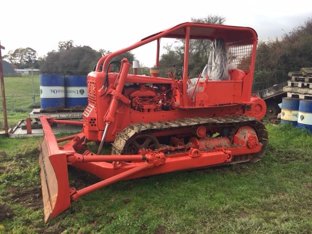
Luckily, my buddy Daron has three surplus military deuce and
a half engines, each with American Bosch fuel pumps. I made a quick trip up the hill to California
City for spare parts.
He acquired these engines through a government liquidation
auction back around 1980. They haven’t
run or rotated since then, but they’ve been pretty well protected. Two have the pumps still mounted and plumbed,
but one had the pump removed and sitting next to the engine in the crate. We took that one because it was easy.
[url=https://postimg.org/image/on2364f45/]https://s26.postimg.org/6x0el31jd/20180121_063430.jpg" />[/url]
[url=https://postimg.org/image/oaaozy4k5/]https://s26.postimg.org/hju7qiheh/20180121_063445.jpg" />[/url]
[url=https://postimg.org/image/lg7jmh7it/]https://s26.postimg.org/cl6pbyiqh/20180121_063512.jpg" />[/url]
It is a PSB6 pump, although a slightly different
variant. Hopefully the internal parts I
need will be the same as mine.
The military pumps have an interesting timing advance
mechanism between the pump and the engine accessory drive. It apparently works from oil pressure, as it
has a line that connects from the pump oil supply to its housing.
[url=https://postimg.org/image/7cboe1q0l/]https://s26.postimg.org/m8a7ln1fd/20180121_072609.jpg" />[/url]
I separated them and can see it has a slight helical gear
with springs which push the drive out on the helix. As oil pressure (or perhaps shaft RPMs)
increase, the springs are compressed and the helix changes the injection timing
slightly.
[url=https://postimg.org/image/5xa3pb9hx/]https://s26.postimg.org/8eluwkteh/20180121_072615.jpg" />[/url]
[url=https://postimg.org/image/xxe79m03p/]https://s26.postimg.org/d0hz4y22x/20180121_072621.jpg" />[/url]
[url=https://postimg.org/image/v3b1w5ihx/]https://s26.postimg.org/esaxzu609/20180121_072626.jpg" />[/url]
[url=https://postimg.org/image/m8a7ll3z9/]https://s26.postimg.org/hme3d8ig9/20180121_072629.jpg" />[/url]
After separating the variable timing drive, the first order
of business was to remove the governor control shaft. If this sleeve locator tang was intact, I
didn’t want to risk breaking this one.
Pulling the shutoff cover, the inside was promisingly clean and rust
free.
[url=https://postimg.org/image/n80ihdylh/]https://s26.postimg.org/yx4i5cpk9/20180121_063623.jpg" />[/url]
I removed the hairpin clip on the governor shaft, pushed the
shaft back through the pivot arm and removed the two shaft retainer screws and
clamp. They all came off nicely and
easily.
I tried to be careful not to put any rotating force to the
shaft at all. I tried to pry carefully
on the retainer ears and the governor arm itself. Nothing wanted to move.
I gradually escalated my efforts, prying a little harder
each time. I couldn’t get the shaft or
retainer to budge. I finally resorted to
trying to very slightly rotate the shaft retainer ears, thinking perhaps it was
gummy or a bit stuck.
At first I couldn’t even get the shaft to rotate at
all. Eventually I was able to just very
slightly rotate the retainer a fraction one way, then a fraction the
other. I felt confident that I wasn’t
moving it enough to shear the tang off.
I was just moving it enough to have a barely perceptible movement.
I kept prying gently while very slightly rotating it one
way, then the other. One time, I pried a
bit too hard and broke off one of the shaft retainer ears, but it still wouldn’t
come out.
Finally, I decided to apply some heat, so I carefully and
gently heated the hydraulic head around the area where the shaft
penetrates. I was taking a risk because
of the rubber seal behind the shaft and the other passages and seals inside the
head, but I had to get the shaft out one way or another.
Eventually, after several cycles of heat, working slightly back
and forth and prying, getting it a bit hotter each time, I got the shaft to
come out.
Unfortunately, once the shaft was out, it was apparent that
its tang had been sheared long ago and the shaft, the sleeve and what I could
see of the plunger were very crusty and corroded. Apparently this part of the system had
suffered from years of being empty with an opening to humidity.
[url=https://postimg.org/image/bb8vwymed/]https://s26.postimg.org/xzy2wj3s9/20180121_120220.jpg" />[/url]
[url=https://postimg.org/image/rm8ztam1h/]https://s26.postimg.org/5ab6zwmxl/20180121_120227.jpg" />[/url]
[url=https://postimg.org/image/n80ihdylh/]https://s26.postimg.org/yx4i5cpk9/20180121_063623.jpg" />[/url]
[url=https://postimg.org/image/m5qbytd79/]https://s26.postimg.org/6x0el1jix/20180121_071148.jpg" />[/url]
[url=https://postimg.org/image/lsyxsosdh/]https://s26.postimg.org/eczo6w4o9/20180121_071153.jpg" />[/url]
Obviously, this pump wasn’t going to be a donor for a sleeve
control shaft. That is O. K. Daron has two more we can investigate for
that piece and this pump still might have the other parts I need.
I pulled the quill shaft out, which looked great.
[url=https://postimg.org/image/uds9jrn39/]https://s26.postimg.org/ml1lrsh49/20180121_073008.jpg" />[/url]
[url=https://postimg.org/image/lirf9960l/]https://s26.postimg.org/d0hz4wzi1/20180121_073041.jpg" />[/url]
[url=https://postimg.org/image/js8e7ee39/]https://s26.postimg.org/cc94llqe1/20180121_073049.jpg" />[/url]
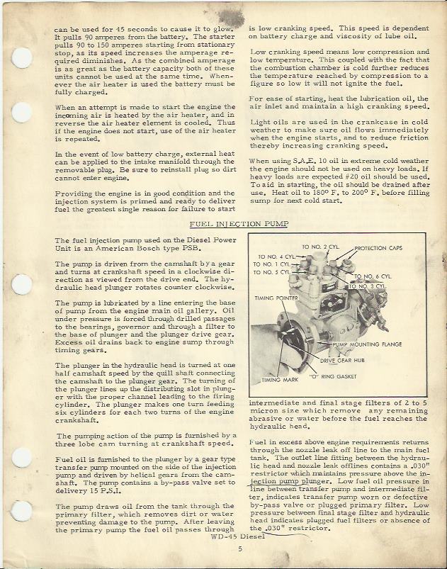
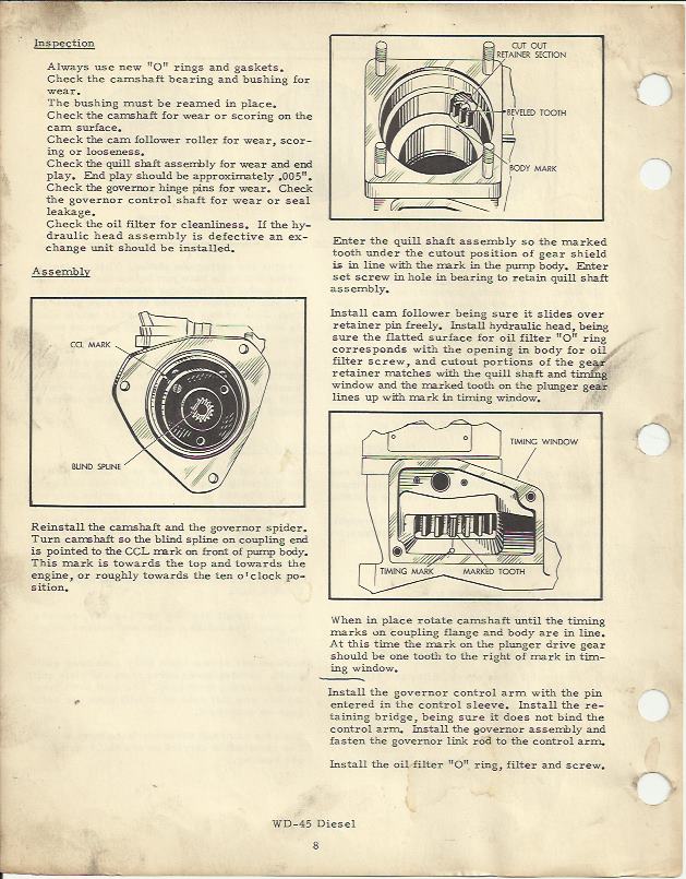
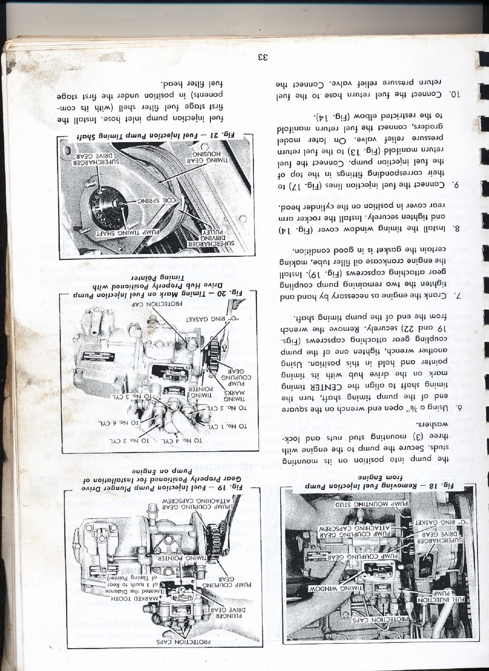
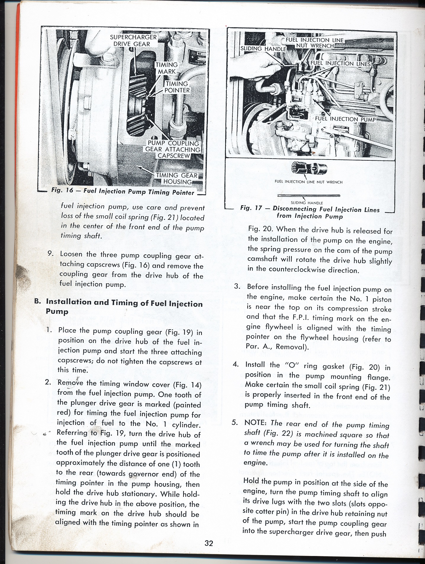
One point I’d like to confirm with those who have been there
before me relates to aligning the sheet metal window on the quill shaft
hat. I assumed that I need to align the
timing pointer on the pump drive with the timing mark, then install the quill
shaft such that the window in the hat faces out, allowing the hydraulic head
gear to drop in.
In this photo, you can see the pointer, with the timing mark
about twenty degrees past the pointer.
[url=https://postimg.org/image/5lsncly7p/]https://s26.postimg.org/4jigu2feh/20180121_083817.jpg" />[/url]
Here is how I installed the quill shaft with the line
aligned with the pointer. It made me a
bit nervous that the sheet metal hat isn’t quite centered, but I tried one
tooth in either direction and this is clearly the best fit.
[url=https://postimg.org/image/oe4ig7a1h/]https://s26.postimg.org/urtljgexl/20180121_084239.jpg" />[/url]
Now, my problem is to find out how to put the No. 1 cylinder
on top dead center of the compression stroke.
I found the timing window on the flywheel housing. It is in an easy to get to spot which is
impossible to see because of the torque converter hoses and other stuff in the
way.
I pulled the valve cover and rotated the engine by hand a handful
of times, identifying when the No. 1 cylinder valves were rocking from one
closing to the other opening. From
there, I rotate the engine three hundred sixty degrees, figuring that should be
close to top dead center.
Garlic Mom got her flashlight and hand mirror and squeezed
between the tire and frame to watch the timing window for me.
[url=https://postimg.org/image/ax7jxbs05/]https://s26.postimg.org/rkz1ztmrt/20180121_095320.jpg" />[/url]
We went back and forth about thirty degrees on either side
of where I thought top dead center was.
We decided that this hole and circle must be the top dead center mark,
as it seemed to be just in the right spot.
That spot also corresponded pretty well with 360 degrees from the valve
rock point. Is this really the timing
mark?
[url=https://postimg.org/image/iegrc3745/]https://s26.postimg.org/96oive021/20180121_100343.jpg" />[/url]
[url=https://postimg.org/image/7245uab9x/]https://s26.postimg.org/pug0xv7o9/20180121_100531.jpg" />[/url]
If it is, I should be at top dead center for the No. 1
cylinder. By the way, I assume that No.
1 is the one closest to the fan and furthest from the flywheel.
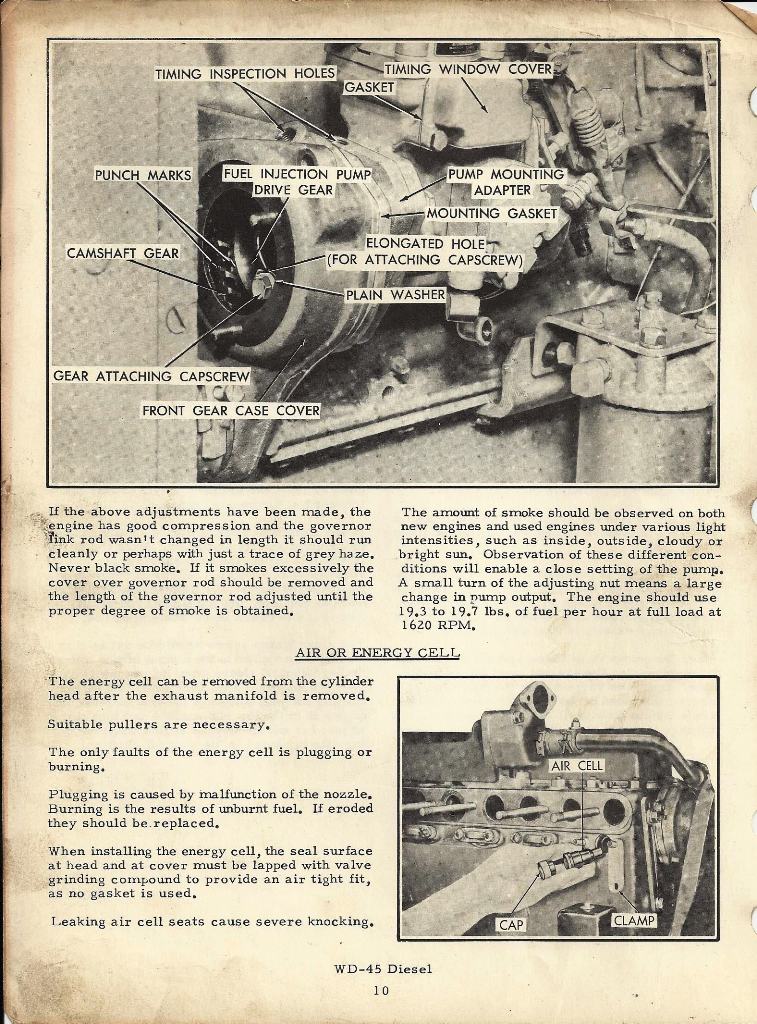
I see that the pump drive gear has a FRONT mark and a timing
punch mark on a tooth immediately below that FRONT mark.
[url=https://postimg.org/image/v5uximjh1/]https://s26.postimg.org/xafajpl3t/20180121_102105.jpg" />[/url]
If I’m right about the position of the engine, I expected to find a timing mark on the
accessory drive gear. I couldn’t find
anything though.
[url=https://postimg.org/image/ipy7pf0l1/]https://s26.postimg.org/4w9v0d7zt/20180121_102304_001.jpg" />[/url]
[url=https://postimg.org/image/qwq7gg0s5/]https://s26.postimg.org/e5c19xr09/20180121_102306.jpg" />[/url]
[url=https://postimg.org/image/cc94m50tx/]https://s26.postimg.org/qiovhdbp5/20180121_102329_001.jpg" />[/url]
[url=https://postimg.org/image/d31urcq6d/]https://s26.postimg.org/rm8zsrjbd/20180121_102330_001.jpg" />[/url]
[url=https://postimg.org/image/te1yo6aj9/]https://s26.postimg.org/9w7b88dll/20180121_102333.jpg" />[/url]
[url=https://postimg.org/image/6pcro7nw5/]https://s26.postimg.org/alq3k78vt/20180121_102355_001.jpg" />[/url]
[url=https://postimg.org/image/ly2p2e29h/]https://s26.postimg.org/ypgv8wc1l/20180121_102358.jpg" />[/url]
I see that the pump drive gear has slotted bolt holes. I assume I need to find the timing mark on
the accessory drive gear and set the gear in, then align the pump drive flange
score to the pump timing pointer, then tighten down the drive gear on to the
pump drive flange. That will ensure the
quill shaft hat window will allow the hydraulic head to drop on. At the same time, the hydraulic head rotator
gear will be timed because the marked tooth will be aligned with the timing
pointer in the timing window of the pump itself.
Those in the know, please confirm the above pump
installation procedures. If I’m right
about the procedure, maybe I don’t need to worry too much about timing marks
between the accessory drive gear and the pump drive gear. As long as the engine really has No. 1 at top
dead center on the compression stroke and I have enough room in the pump drive
gear slots to align the pump drive flange score mark with the pump timing
pointer, everything should be O. K.
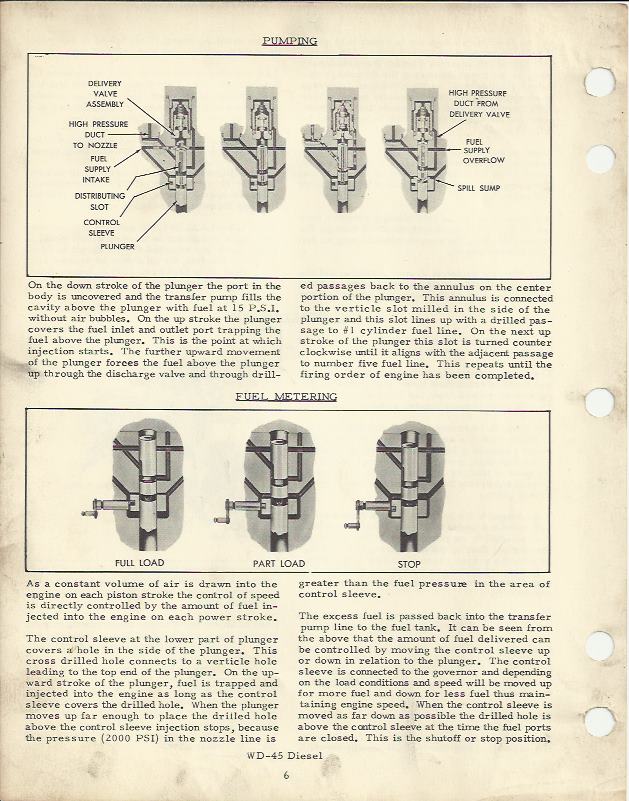
Now for some questions about the rotating gear, the tin
cover for it and the drive from the rotating gear to the plunger itself.
I can see that the tin cover is assembled by slipping it
over the rotating gear and hydraulic head flange, then it is crimped in four
places and staked at one place (which should keep it from rotating).
Since my tin cover got chewed up, I didn’t see any loss by
prying it off.
[url=https://postimg.org/image/z289eszdh/]https://s26.postimg.org/6pcrocdnd/20180121_103818.jpg" />[/url]
[url=https://postimg.org/image/ei3fgbrc5/]https://s26.postimg.org/96oivm59l/20180121_103819.jpg" />[/url]
[url=https://postimg.org/image/ir85ihf5x/]https://s26.postimg.org/84ecd270p/20180121_103820.jpg" />[/url]
If I had to, I think I could straight this cover out and
salvage it, but I think I’m better off to carefully remove the tin cover from Daron’s
donor pump. It appears to be in perfect
shape and I don’t see any differences in this area between the two pumps.
If I can remove the tin cover from the donor pump, should I
be O. K. to just recrimp in the same four places with a screwdriver, then stake
it with a punch in the same place as is provided on both hydraulic heads?
Once I had the tin cover off, I could see what I think are
other problems. The rotating gear
operates on what I think is supposed to be a one piece collar which has two
ears engaged in recesses in the rotating gear and has a square opening through
which the square part of the plunger shaft passes.
On my pump, this collar is in two pieces. It must have split when the plunger was seized
and the engine was first rotated. It is
possible that it is supposed to be in two pieces, I haven’t taken apart the
donor hydraulic head yet.
I don’t think it is supposed to be in two pieces because the
two pieces aren’t symmetrical and the plunger shaft is able to move rather a
lot in relation to the rotating gear.
Here are some pictures of the assembly as it is now, including a couple
which show the plunger shaft rotated within the collar one way, then the other.
[url=https://postimg.org/image/w8541chrp/]https://s26.postimg.org/7245uighl/20180121_105737.jpg" />[/url]
[url=https://postimg.org/image/xafajvsv9/]https://s26.postimg.org/5ztzbypyh/20180121_105744.jpg" />[/url]
[url=https://postimg.org/image/tqtcucddh/]https://s26.postimg.org/7evk0ye9l/20180121_105748.jpg" />[/url]
[url=https://postimg.org/image/4ksengu2t/]https://s26.postimg.org/3v9mb3tjd/20180121_105752.jpg" />[/url]
The plunger does rotate with the gear, but I’d estimate
there is probably fifteen or twenty degrees of play with the system the way it
currently is. I can’t imagine this is
acceptable. Without disassembling the
donor hydraulic head, I can see that all the rotating gear and drive stuff is
in good shape and doesn’t appear to have the slack that this system has. Is it likely I can swap the drive collar from
the donor pump onto this one?
I know I can’t swap plungers, as they’re matched. I would expect this drive collar and the
square part of the plunger to be standardized though, so I hope exchanging the
drive collar shouldn’t be a problem.
That leads me to what I hope is my last question: If the drive collar can be exchanged, I have
four possibilities to assemble the rotating gear onto the plunger shaft. How do I time the shaft to the drive
collar? Is it as simple as aligning the
spill slot in the plunger with the timing tooth on the rotating gear? Maybe there is a timing mark on the plunger
shaft end that I haven’t noticed?
Thanks for any help the group can give me.
I think if I can accumulate all the knowledge and hopefully
find one good governor control shaft with a good tang on it from Daron, I might
be able to reassemble this thing and hear it run next weekend.
Pete.


 Topic Options

 Post Options
") Thanks(0)
Thanks(0)


 DMiller wrote:


